
Operator-based Viewpoint Definition
Johannes Meier
1
, Ruthbetha Kateule
2
and Andreas Winter
1
1
Software Engineering Group, University of Oldenburg, Oldenburg, Germany
2
Computer Science and Engineering, University of Dar es Salaam, Dar es Salaam, Tanzania
Keywords:
View, Viewpoint, Viewpoint Definition, View Definition, Operator, View-update.
Abstract:
With the increase in size, complexity and heterogeneity of software-intensive systems, it becomes harder
for single persons to manage such systems in their entirety. Instead, various parts of systems are managed
by different stakeholders based on their specific concerns. While the concerns are realized by viewpoints,
the conforming views contain projected parts of the system under development. After analyzing existing
techniques to develop new viewpoints and views on top of existing systems, this paper presents an approach
that defines new viewpoints and views in a coupled way based on operators. This operator-based approach is
used to define new viewpoints and views for an existing Module-based description of architectures.
1 MOTIVATION
The growth of size, complexity and heterogeneity of
software-intensive systems results in the growth of
size and complexity of systems descriptions during
development. Thus it becomes more difficult for one
person to manage all the related concepts and infor-
mation of systems. To manage such increasing infor-
mation required for the description of the whole sys-
tem, only a subset of the existing information should
be handled rather than all information together. Hav-
ing only a subset of such information allows focusing
on the currently relevant aspects of the system only
while ignoring all other aspects. The currently rele-
vant aspects depend on the tasks of the current person
working on the system, on the development phase and
on functional building blocks of the system. All these
relevant aspects are referred as concerns of the differ-
ent people like developers, designers, testers, project
manager, requirements engineers, and so on. Since
different people involved with the system represent
different stakeholders with different concerns, lots of
different views on the system are required.
These ideas motivate the use of multiple view-
points and views: Following the ISO Standard for
Architecture Description 42010:2011 (IEEE, 2011),
views describe parts of the system under development
that address specific concerns, and help stakeholders
with these concerns to work on the parts of the sys-
tem, that are matched by their concerns. Viewpoints
determine, which information of the system should be
contained in conforming views. In this paper, views
are realized as models and visualized as UML object
diagrams, while viewpoints are realized as metamod-
els and visualized as UML class diagrams.
To assemble and manage several views show-
ing parts of the same underlying system, (Atkinson
et al., 2009) presented the idea of Single Underlying
Models (SUM) which contains all information of the
whole system under development in an integrated and
consistent way (Margaria and Steffen, 2009). The
stakeholders do not work directly on the SUM, but
use views which are projected from the SUM. Us-
ing views, the stakeholders can work “in isolation”
on only the currently relevant aspects. After finishing
their work, changes made in the views are transmit-
ted into the SUM automatically to keep it up-to-date.
Since all views are projected from the SUM, the views
remain consistent to each other. The SUM is explic-
itly realized as model conforming to the explicit Sin-
gle Underlying MetaModel (SUMM).
Therefore, the goal of this paper is to enable new
views projected from an existing SUM: Following the
SUM idea, this paper presents an operator-based ap-
proach to define new viewpoints on top of a SUMM
in Section 4, along a running example introduced in
Section 2. Section 3 analyzes related work, derives
challenges for view definitions and points to the con-
tributions of the new approach. Section 5 presents
more applications to demonstrate the applicability of
the new approach. The contributions of this paper and
its approach are summarized in Section 6.
Meier, J., Kateule, R. and Winter, A.
Operator-based Viewpoint Definition.
DOI: 10.5220/0008977404010408
In Proceedings of the 8th International Conference on Model-Driven Engineering and Software Development (MODELSWARD 2020), pages 401-408
ISBN: 978-989-758-400-8; ISSN: 2184-4348
Copyright
c
2022 by SCITEPRESS – Science and Technology Publications, Lda. All rights reserved
401
Module
name : EString [1]
SubSystem
Configuration
name : EString [1]
Interface
Layer
name : EString [1]
abstract
InterfaceElement
containedModules [∗] layer [0..1]
containedModules [∗]
subsystem [1]
parentModule [0..1]
childModules [∗]
communicatesWith [∗] communicatedBy [∗]
parentSubsystem [0..1] childSubsystems [∗]
subsystems [∗]
configuration [0..1]
configuration [1]
interfaces [∗]
configuration [0..1]
layers [∗]
provided [∗] providedBy [∗]
required [∗] requiredBy [∗]
parentLayer [0..1] childLayers [∗]
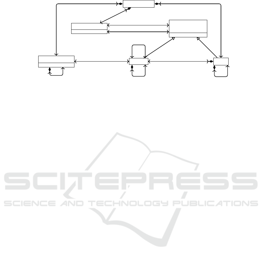
Figure 1: Metamodel describing architectures of SEISs, used as SUMM in the running example to derive new viewpoints.
2 VIEW(POINT)S ON MODULES
As running example for this paper, an existing
module-based description for architectures of Smart
Environmental Information Systems (SEISs) (Kateule
and Winter, 2016), adopted from (Hofmeister et al.,
2000), is chosen and treated as SUMM. SEISs re-
fer to those systems which incorporate the sensing
and actuating techniques to observe, analyze and con-
trol certain environmental phenomena such as for-
est fires,flood,air pollution,landslides.The Module de-
scription addresses the concerns of system architects,
project manager and development experts which are
related to how the SEIS is technically realized. It is
treated as SUMM in this paper, since it contains dif-
ferent aspects which are usable for new (sub) view-
points and organized in an integrated way.
The used metamodel for this Module description
is shown in Figure 1 which describes the essential ele-
ments for architectures of SEIS, mainly software im-
plementation modules, their interfaces and relation-
ships required for the construction of modules. A
module represents a set of functionalities of SEISs
that can be realized and provided as a service. The
modules of SEISs are organized into two orthogonal
structures such as decomposition and layering. The
decomposition encompasses how the system is de-
composed into subsystems and modules, while lay-
ering demonstrates how the modules are assigned to
layers. Subsystems can contain other subsystems or
modules. Modules can interact with each other di-
rectly, if they belong to the same layer. The interac-
tion of modules across different layers is facilitated
by both required and provided interfaces.
On instance level, a very small example SEIS
is used as SUM in this paper, shown in Figure 2
as object diagram: The whole SEIS is represented
by one subsystem named “SEIS System” (sub0),
which is divided into two subsystems for the “Sensor-
Subsystem” (sub2) and the “ControlCentre” (sub1).
The sensor-subsystem measures physical environ-
ment events, i.e., temperature, humidity etc.. The
control center refers to the subsystem, which inte-
grates and analyses information gathered by sensor-
subsystem to determine the likelihood of certain envi-
ronmental phenomena. The system is structured tech-
nically into two layers: data management (l2) and
application logic (l1). Inside the application layer,
the “Analyzer” module (m2) analyses data collected
by sensor-subsystem to detect the environmental phe-
nomena. The required data are provided directly by
the “Acquisition” module (m1), which are stored in
the “DataBase” module (m3). The acquisition mod-
ule obtains data from the real world by allowing the
collection of data from either digital or analog sen-
sors. The database module is used to store data. Since
these two modules m1 and m3 are located in differ-
ent layers, the communication between them uses the
“DataAccess” interface (i1). The root object is re-
quired only for technical reasons introduced by the
underlying Eclipse Modeling Framework (EMF).
The decomposition of the modules in sub-modules
and their grouping by layers and subsystems is the
main goal of the Module description and helps mainly
architects to design the structure of the system un-
der development. Since the subsystem can be used to
structure the system and its modules regarding func-
tionality, subsystems are also helpful for the project
manager: To measure the progress of the develop-
ment project and to estimate the required develop-
ment effort for subsystems, the project manager needs
the mapping of the subsystems with the layers, but
without being overburdened by the more detailed
modules. Therefore, the project manager wants to
use a new viewpoint called “Intersections” (Figure 3)
with only the following concepts: (1) subsystems with
their decomposition (2) layers with their decomposi-
tion (3) information about systems having intersec-
MODELSWARD 2020 - 8th International Conference on Model-Driven Engineering and Software Development
402
root : Configuration
name = ”SEIS System”
sub0 : SubSystem
name = ”ControlCenter”
sub1 : SubSystem
name = ”Sensor-Subsystem”
sub2 : SubSystem
name = ”DataAccess”
i1 : Interface
name = ”Application”
l1 : Layer
name = ”Data”
l2 : Layer
name = ”Acquisition”
m1 : Module
name = ”Analyzer”
m2 : Module
name = ”DataBase”
m3 : Module
configuration[0]
subsystems[0]
configuration[0]
interfaces[0]
configuration[0]
layers[0]
configuration[0]
layers[1]
parentSubsystem[0]
childSubsystems[0]
parentSubsystem[0]
childSubsystems[1]
subsystem[0]
containedModules[0]
subsystem[0]
containedModules[0]
subsystem[0]
containedModules[1]
provided[0]
providedBy[0]
provided[0]
providedBy[1]
required[0]
requiredBy[0]
layer[0]
containedModules[0]
layer[0]
containedModules[1]
layer[0]
containedModules[0]
communicatedBy[0]
communicatesWith[0]
Figure 2: Model describing the architecture of a small SEIS, used as SUM in the running example to derive new views.
name : EString [1]
SubSystem
Configuration
name : EString [1]
Layer
sharedModulesWithLayers [∗]
sharedModulesWithSubsystems [1]
parentSubsystem [0..1]
childSubsystems [∗]
subsystems [∗]
configuration [0..1] configuration [0..1]
layers [∗]
parentLayer [0..1]
childLayers [∗]
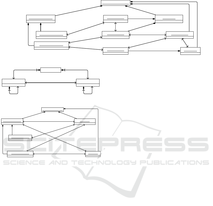
Figure 3: Intersections viewpoint, subset of Figure 1.
root : Configuration
name = ”SEIS System”
sub0 : SubSystem
name = ”ControlCentre”
sub1 : SubSystem
name = ”Sensor-Subsystem”
sub2 : SubSystem
name = ”Application”
l1 : Layer
name = ”Data”
l2 : Layer
configuration[0]
subsystems[0]
configuration[0]
layers[0]
configuration[0]
layers[1]
parentSubsystem[0]
childSubsystems[0]
parentSubsystem[0]
childSubsystems[1]
sharedModulesWithSubsystems[0]
sharedModulesWithLayers[0]
sharedModulesWithSubsystems[0]
sharedModulesWithLayers[0]
sharedModulesWithSubsystems[1]
sharedModulesWithLayers[1]
sharedModulesWithSubsystems[1]
sharedModulesWithLayers[0]
sharedModulesWithSubsystems[2]
sharedModulesWithLayers[1]
Figure 4: Intersections view, subset of Figure 2.
tions with layers regarding the same modules. Instead
of the complex model shown in Figure 2, the project
manager wants to work only with the model shown in
Figure 4, which contains all relevant data, but none of
the superfluous data, thus reducing unnecessary com-
plexity. This Intersections viewpoint is used as the
running example in the paper. Some more examples
for new viewpoints are given in Section 5.
3 RELATED WORK
To realize the SUM idea as motivated in Section 1,
(Meier et al., 2019) discusses and compares some
existing SUM approaches, which contribute related
work also on how to define new viewpoints on top
of an existing SUMM: The “Orthographic Software
Modeling” approach (OSM) (Atkinson et al., 2009)
realizes the SUM idea by storing all information
about the system under development inside one ex-
plicit model, the SUM, without any redundancies and
dependencies, and a conforming SUMM. All views
are projected on-demand from the SUM by executing
a model transformation. Since OSM supports multi-
level modeling, DeepATL (Atkinson et al., 2013) as
an extension of ATL with multi-level modeling is
used. To propagate changes back into the SUM, trace
links between view and SUM are used (Tunjic and
Atkinson, 2015).
Another approach for the creation of new views is
realized with ModelJoin (Burger et al., 2014), which
takes several (meta)models as input and provides the
resulting output model as view including its meta-
model to the stakeholder. ModelJoin is a textual DSL,
whose execution results in model, metamodel and
model transformations for the new view(point).
The ModelJoin approach was developed in the
frame of the Vitruvius approach (Kramer et al., 2013)
as another SUM approach. Vitruvius realizes the
SUM idea by combining already existing metamod-
els and models internally as modular SUM and by
providing views to the stakeholders as in the origi-
nal SUM idea. These views are combined from the
internal models using ModelJoin.
Another SUM approach is the “Role-oriented Sin-
gle Underlying Model” (RSUM) (Werner and Ass-
mann, 2018), which combines existing metamodels
and models into one explicit SUM(M) by adding role-
based associations between them. New viewpoints
are realized by reusing the ModelJoin approach.
Independent from SUM approaches, generic
model transformations (Mens and Van Gorp, 2006;
Jakumeit et al., 2014) are used to create views: The
existing SUM and SUMM are used as source model
and source metamodel, while the output model is pro-
vided for the stakeholder as the view conforming to
the output metamodel which is the viewpoint. Since
the output metamodel often has to be defined before
writing the model transformation, these two artifacts
have to be kept consistent to each other: Changes in
the target metamodel require changes in the model
transformation and vice versa. Since this is main-
tained often manually, the coupled evolution of tar-
get metamodel and model transformation is source for
possible inconsistencies. This counts also for OSM.
Operator-based Viewpoint Definition
403

The technical relationship between SUM and view
is often described by one whole, comprehensive trans-
formation. This allows to write them compactly, but
hinders the reuse of parts of the written transforma-
tion, e.g. for the definition of similar viewpoints.
Since such transformations are executed en bloc, de-
bugging the transformation is difficult, since stable in-
termediate states are missing. This counts also for
OSM and ModelJoin.
Another approach to define viewpoints on top of
a metamodel is presented in (Cicchetti et al., 2011):
For all meta-classes and their attributes and associa-
tions in the metamodel can be decided, whether they
should be part of the new viewpoint or not. Although
this simplifies the definition of the viewpoint and the
back-propagation of changes, the stakeholder as a
user of the new view is supported with views only
in moderately quality and usability. Because the se-
lection of existing parts of the metamodel is possible
only without restructurings and adding computed val-
ues, the view(point) cannot be tailored specifically to
the concerns of the stakeholders, but inherits the qual-
ity of the initial (meta)model. This counts also for
model pruning approaches like (Sen et al., 2009).
The approach presented in Section 4 targets
mainly transformations between SUMM and view-
point divided into reusable units. This targets to spec-
ify new viewpoints easier by reuse, an iterative pro-
cedure and stable intermediate steps for debugging.
Additional design goals are viewpoints which differ
from the initial structure and are kept in sync with the
transformations. The work of this paper extends Mo-
ConseMI as another SUM approach, showing that is
possible not only to integrate several data sources into
a new SUM(M) (Meier and Winter, 2018), but also to
derive new viewpoints from an existing SUMMs.
4 VIEWPOINT DEFINITION
APPROACH
The main idea of the new approach to define view-
points and views is to split up the transformations
into a sequence of small transformations. Each of
the small transformations is realized by an operator
(Section 4.1), which should be reusable to define new
viewpoints easier. Another design goal is to keep the
model transformations between SUM and view con-
sistent to the final viewpoint.
4.1 Operators
Each operator realizes a small part of the whole trans-
formation between SUM(M) and view(point): Input
for each operator is the current metamodel and con-
forming model. After a small change in the meta-
model and conforming changes in the model, these
changed metamodel and model are the output of the
operator and serve as input for the next operator. This
design allows the creation of chains of operator form-
ing arbitrarily long transformations.
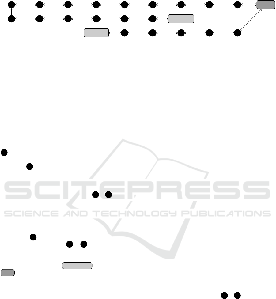
The third row of Figure 5 shows the chain of
operators configured for the transformation of the
SUM(M) into the Intersections view(point): Operators
are depicted along edges, while the connected nodes
before and after are input or output for this operator.
As example, the operator AddDeleteAssociation
takes the SUM(M) as input and adds a new associ-
ation to the SUMM, which results in a changed meta-
model for 16 as output. This operator was chosen to
store intersections between subsystems and layers for
the project manager. The operator was configured to
calculate and store intersections by linking each sub-
system with those layers which contains at least one
module which is part of the subsystem.
To be reusable, each operator can be configured
regarding its changes in the metamodel: As an exam-
ple, the operator AddDeleteAssociation provides
metamodel decisions for the source and target class
which should be connected by the new association.
Complementary, each operator changes the model to
keep it conform to the changed metamodel and ful-
fills the required model-co-evolution. This operator-
based coupled evolution of metamodels and mod-
els is introduced by (Herrmannsdoerfer et al., 2011)
and is extended here: Since the model-co-evolution
has some degrees of freedom how to change the
model to keep it conform to the changed metamodel,
each operator can define model decisions to control
these degrees of freedom: As an example, the op-
erator AddDeleteAssociation allows adding arbi-
trary links in the model for the new association in
the metamodel. By this design, the main functional-
ity of the operator AddDeleteAssociation to create
new associations can be realized once and provided
as reusable operator. All operators are provided in a
reusable library. An incomplete version of it can be
found in (Meier and Winter, 2018).
In contrast to model transformation chains (L
´
ucio
et al., 2013), instead of whole transformations,
only small recurring transformation patterns are
reused, while their configuration is project-specific.
As other action-based approaches managing models
like (Mosser and Blay-Fornarino, 2013), only the
model level is addressed, while the metamodels are
also required to get the new viewpoints.
The orchestration of operators like in Figure 5
is done only once and manually by selecting opera-
MODELSWARD 2020 - 8th International Conference on Model-Driven Engineering and Software Development
404
SUM(M)
ModulesOnly
15
Delete Add
Association
14
Add Delete
Association
13
Delete Add
Association
12
Add Delete
Association
11
Add Delete
Association
10
Add Delete
Association
09
Add Delete
Class
08
Change
Multiplicity
07
Rename
Classifier
06
Inline Sub
Class
05
Rename
Classifier
04
Make Class
Non Abstract
03
Sub Set Classes
02
Change Model
01
Change
Containments
Of Class
Add Delete
Association
Intersections
20
Rename
Classifier
19
Inline Sub
Class
18
Rename
Classifier
17
Make Class
Non Abstract
16
Sub Set Classes
Add Delete
Association
Figure 5: Chains of configured operators to define two new view(point)s Intersections and ModulesOnly on the SUM(M).
tors from the library, configuring them and combin-
ing them as chain of operators. Afterwards, this or-
chestration is stable and can be executed several times
automatically: Executing the chain of operators with
the SUM(M) as starting point results in the projected
viewpoint and the projected view. Since the view-
point is generated out of the operator chain, it is al-
ways in sync with the configured transformation. In
contrast to some generic model transformation lan-
guages, the operators change metamodel and model
in-place to avoid copying the whole model for each
operator, which improves performance.
After calculating and storing the intersections in
16 for the running example, the modules and in-
terfaces are removed by using the SubSetClasses
operators 17 , which is described with some more
details in Section 4.3. Finally, the meta-classes
InterfaceElement and Layer should be com-
bined to ease the new view(point): This is done
by the operator InlineSubClass 19 →20 , while
the remaining operators RenameClassifier and
MakeClassNonAbstract support that.
This chain of operators also show, that new view-
points can be defined in iterative way: The model and
metamodel after calculating the intersections can be
analyzed at 16 , before the following operators reduce
the existing information at 17 . . . 20 . This helps to an-
alyze and debug the single steps of the transformation
and allows development in steps over time.
After projecting the Intersections view from the
SUM , the project manager can read and change the
Intersections view. This leads to the challenge to
propagate changes in the view back into the SUM,
which is discussed in the next Section 4.2.
4.2 View-update-Problem
The Intersections view allows the project manager
not only to analyze possible intersections, but also
to change things, e.g. to rename an existing layer.
To keep the SUM up-to-date, these changes have to
be propagated from the view to the SUM. This leads
to the known view-update problem (Bancilhon and
Spyratos, 1981). In related approaches like (Cicchetti
et al., 2011), which uses a subset of the SUMM with-
out any structural changes or refactorings, changes
made in the view can be applied directly to the SUM.
Since the approach of this paper supports changes in
the new viewpoint (Figure 3) compared to the SUMM
(Figure 1), a more complex solution is required here.
The main idea to update the SUM is to execute
the configured chain of operators in inverse direction
to transform the (changed) view into the (changed)
SUM. For that, each operator is combined with an
inverse operator: Two operators A and B are inverse
to each other, if the metamodel after applying A and
B is the same as before executing these two opera-
tors. In other words, B reverts the metamodel changes
that are done by A. Therefore, the presented opera-
tor AddDeleteAssociation represents the operator
AddAssociation combined with its inverse opera-
tor DeleteAssociation. Each operator is combined
with an inverse operator. Therefore, translating the
viewpoint back into the SUMM is ensured automati-
cally by the design of the operators.
Looking at the model level, after executing the
operator chain in the inverse direction it is also en-
sured automatically, that the resulting SUM is still
conforming to the SUMM, because the model-co-
evolution done by the operators is fixed accordingly
to the metamodel changes. More interesting are
the degrees of freedom provided by the model de-
cisions: Model changes triggered by model deci-
sions of an operator has to be inverted by the in-
verse operator. For the AddDeleteAssociation
operator, this is easy, since all added links are
deleted by the inverse operator as part of the reg-
ular model-co-evolution. More complex is the
Inline/ExtractSubClass operator, which is also
used in the running example 19 → 20 : After inlin-
ing a sub-class (InlineSubClass), the inverse oper-
ator extracts the sub-class again (ExtractSubClass).
On the model level, the instances migrated to the
super-class have to be migrated back to the recre-
ated sub-class again. The selection of the instances
of the super-class to migrate to instances of the sub-
class is controlled by a model decision. This model
decision has to be carefully decided for the current
situation to match only the instances migrated by
InlineSubClass previously.
Finally, the view-update problem is solved once
and manually by configuring the model decisions ap-
Operator-based Viewpoint Definition
405

propriately to realize the wanted back-propagation of
changes. The operator’s design ensures the meta-
model level and the general model-co-evolution, but
the semantic details have to be ensured manually
by the coordinated and consistent configuration of
the operators. Summarizing, changes in the views
are propagated into the SUM by transforming the
changed view back into the changed SUM.
4.3 Information Loss
Since stakeholders want to use views only with infor-
mation tailored to their specific needs, only a subset
of the information contained in the SUM is shown in
views. Since using a view should be done “in isola-
tion” from all other views and the SUM, the approach
of this paper removes information step-wisely during
the transformation of the SUM to the view, done by
the operator chain. To transfer the changed view back
into the SUM, the operator chain is executed in the
inverse direction, as explained in Section 4.2. Since
the operators work in-place, the operators have to re-
store previously removed information again to prevent
a loss of information in the updated SUM. Three dif-
ferent solutions are available to realize that.
The first solution is to use operators like
Add/DeleteClass, Add/DelteAssociation und
Add/DeleteAttribute to remove unused informa-
tion. During the execution of all operators by the sup-
porting framework, all model changes induced by op-
erators are recorded and stored. For the mentioned
operators, the removed information is stored in the
form of model changes. After executing the inverse
operator to recreate the SUM, a complex algorithm
currently under development is used to invert and ap-
ply the stored model changes again in order to recre-
ate the removed information. Since this mechanism
is provided in a generic way for all operators by the
framework and can be requested if needed, this so-
lution should be preferred. In the running exam-
ple, the used operator SubSetClasses 16 →17 re-
moves the two meta-classes Module and Interface.
SubSetClasses is a composite operator and uses sev-
eral instances of DeleteAddClass internally.
While the first solution is a post-treatment for the
execution of operators not visible to them, the second
solution can be used directly inside the implementa-
tion and configuration of operators: For each com-
bination of a configured operator with its configured
inverse operator a map to store arbitrary information
is available during execution. The map can be used
to read and write information into it during all exe-
cutions of the operator and its inverse operator. As
example, this option is used by the regular model-co-
evolution of the MergeClasses operator to remem-
ber which instances were merged during the last ex-
ecution to merge them now again. Additionally, this
“history map” can be used in configured model deci-
sions to remember some important information. This
can make sense for example in the ChangeModel op-
erator, which allows arbitrary changes in the model,
while the metamodel remains unchanged. Together
with the history map, this operator gives full flexibil-
ity to realize arbitrary views with solving the prob-
lems of view-updates and information loss. This sec-
ond solution is only controlled by the operators and its
model decisions, and therefore requires careful use.
The third solution is a special case supported by
special operators to split a model into two indepen-
dent models, while one of the split models is provided
as output and the other one is stored inside the opera-
tor to be used by the inverse operator to add it again.
Because of this restricted design, this operator is nor-
mally not used for defining new viewpoints.
5 APPLICATION
After presenting the approach for operator-based cou-
pled definition of views and viewpoints, Section 5.1
shows the final result of the running example. Sec-
tion 5.2 discusses a completely new viewpoint, with a
variant in Section 5.3.
5.1 Viewpoint Intersections
As a running example, the Intersections viewpoint
help project managers to detect overlaps of subsys-
tems and layers regarding the same modules. This
information can be helpful to identify possible con-
flicts, to plan resources and to bridge functional units
(the subsystems) with technical units (the layers) as
an overview. After configuring the operators
16 un-
til 20 in Figure 5 to define the Intersections viewpoint
(Figure 3) on top of the SUMM , they help to project
Intersection views like in Figure 4 from the SUM and
to transfer changes back into the SUM afterwards.
A variant of this viewpoint could add the number
of intersecting modules between subsystems and lay-
ers, since in the current design links only indicate, that
there is at least one intersecting module (Figure 3).
5.2 Viewpoint ModulesOnly
Looking into more detail, modules with their commu-
nication are also interesting for developers who real-
ize different communications kinds between modules.
Since they are not that interested in the structuring of
MODELSWARD 2020 - 8th International Conference on Model-Driven Engineering and Software Development
406
Configuration
name : EString [1]
Interface
name : EString [1]
Module
ModuleCommunication
configuration [1]
interfaces [∗]
container [0..1]
modules [∗]
configuration [1]
communications [∗]
provided [∗] providedBy [1]
interface [0..1]
usedBy [∗]
from [1]
commInc [∗]
to [1]
commOut [∗]
parentModule [0..1]
childModules [∗]
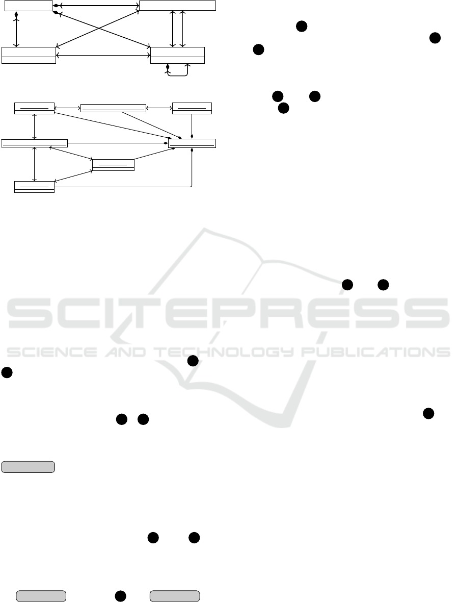
Figure 6: ModulesOnly viewpoint, subset of Figure 1.
root : Configuration
name = ”Interface1”
i1 : Interface
name = ”Module1”
m1 : Module
name = ”Module2”
m2 : Module
name = ”Module3”
m3 : Module
1f5 : ModuleCommunication
e63 : ModuleCommunication
configuration[0]
interfaces[0]
container[0]
modules[0]
container[0]
modules[1]
container[0]
modules[2]
configuration[0]
communications[0]
configuration[0]communications[1]
provided[0]
providedBy[0]
interface[0]
usedBy[0]
from[0]
commInc[0] to[0]
commOut[0]
from[0]
commInc[1]
to[0]
commOut[0]
Figure 7: ModulesOnly view, subset of Figure 2.
modules with layers and subsystems on a more con-
ceptual level, they want to use another new viewpoint
called “ModulesOnly” with only the following con-
cepts (Figure 6): (1) modules with their decomposi-
tion, (2) all communications between pairs of mod-
ules, (3) interfaces used by communicating modules.
Instead of Figure 2, the developers want to work only
with the information shown in Figure 7, which con-
tain only the wanted information as view on the SUM.
The chain of configured operators to realize the
ModulesOnly viewpoint is shown in the first two
rows of Figure 5: The first two operators 01 and
02 are required as technical precondition and change
the EMF containment of the modules from the lay-
ers to the configuration, since the layers will be re-
moved later. Now all subsystems and layers are re-
moved by SubSetClasse 03 →04 , since they are
not relevant for the developers. The previous op-
erator ChangeModel is required to fulfill the view-
update problem: If new modules are created in the
ModulesOnly view, even after restoring subsystems
and layers as described in Section 4.3, new modules
are not related to any subsystem, which is a conflict
to the SUMM (Figure 1). To fix this, ChangeModel
is configured to link each module with one random
subsystem, if there is no linked subsystem.
The following four operators 05 until 08 are
used to combine the meta-classes Module and
InterfaceElement, since the other sub-class Layer
was removed before. Since this is very similar to the
combination of Layer and InterfaceElement for
the Intersections viewpoint (
18 until Intersections , de-
scribed in Section 4.1), the same operators are taken
from the library and reused with slightly different
configurations. This shows, that the operators are
reusable and that there is a need for reusable parts of
the transformations between SUM and new views.
Operator 09 ensures that each interface is pro-
vided by exactly one module. The operators 10 un-
til 14 migrate the direct communication of modules
via the looping association communicatesWith in the
SUMM to the more structured representation using
the new ModuleCommunication meta-class. The op-
erators 10 until 13 creates the information first, the
operator 14 removes the old information afterwards.
Since this transformation is done without any infor-
mation loss, there is no need for the strategies to pre-
vent information loss described in Section 4.3. Again,
this step-wise procedure with mapping single opera-
tors to single purposes shows the support for iterative
development and debugging of the operator chain.
The last two operators realize the communica-
tion between modules via an interface by the same
strategy as for the direct communication: The first
operator enables ModuleCommunication to use an
Interface and adds the interface-based commu-
nications on model level. The last operator re-
moves the old representation and all links of the
Module.required association.
Again, the operators 11 until 15 show, that some
functionality like adding a new association is required
several times for different purpose. Therefore, oper-
ators like AddAssociations help to develop trans-
formations between SUM and view faster and eas-
ier, because only variation points like source and tar-
get class for the new association have to be specified,
while the details of the transformation can be skipped
and are internal details of the reusable operator. In
contrast to pre-defined transformations, operators like
ChangeModel provide full flexibility to realize spe-
cific needs for new view(point)s, as used for 03 .
Because the Intersections viewpoint is similar to
the original SUMM, six operators are enough for the
transformation. Since the ModulesOnly viewpoint
describes the communication between modules com-
pletely different as in the SUMM, 16 operators are
required: Growing complexity of viewpoints can be
handled and scaled by longer chains of operators.
5.3 Viewpoint LayersOnly
The ModulesOnly viewpoint helps developers to
structure the system in detail (Section 5.2). In con-
trast to that, software architects are more interested in
layers as the general structure of systems. This counts
in particular for huge systems with lots of layers and
an unmanageable amount of modules inside them.
Therefore, similar to the ModulesOnly viewpoint,
a LayersOnly viewpoint can be specified to sup-
Operator-based Viewpoint Definition
407

port the architect in focusing on only the layers of
the system under development: Additional to the
layers, also their communication with each other
is of interest and can be described similarly like
for modules in Figure 6. One difference is, that
each LayerCommunication always uses exactly one
Interface, since the communication of layers is al-
lowed only using interfaces. Again a chain of opera-
tors can be configured to describe the transformation
of the SUM(M) into the LayersOnly view(point), si-
milar to the chain of operators for the ModulesOnly
viewpoint shown in Figure 5. Most operators used for
the ModulesOnly viewpoint are reused for the Layer-
sOnly viewpoint, but with a slightly different config-
uration. In the end, the ModulesOnly viewpoint and
the LayersOnly viewpoint complement each other by
focusing on different levels of granularity.
6 CONCLUSION
Summarizing, this paper contributes a new approach
to define new viewpoints and views by using oper-
ators. Since the operators split the whole transfor-
mation between SUM(M) and view(point) into parts,
the operators provided as library are designed to be
reusable and generic by using metamodel and model
decisions. The presented exemplary chains of oper-
ators are showing their reusability for different new
viewpoints on top of already existing SUMMs.
The chain of configured operators allows devel-
oping new viewpoints in an iterative way by adding
more and more operators to improve and adapt the
new viewpoint step-wisely to the needs of the stake-
holders. These steps ease also debugging purposes,
since the current (meta)model can be reviewed after
each operator. The framework to realize the opera-
tors and to enable the definition of viewpoints is un-
der development and provides support to overcome
the challenges view-update and of preventing infor-
mation loss, but leaves room for individual solutions
during the manual configuration of operators.
Compared to approaches from the related work in
Section 3, this approach keeps the viewpoint and the
transformation to project the views in sync, because
the viewpoint is generated during the execution of the
operator chain. The presented approach does not use
explicit traces between SUM and new view and al-
lows specifying viewpoints, which differ highly from
the structure of the initial SUMM.
REFERENCES
Atkinson, C., Gerbig, R., and Tunjic, C. V. (2013). Enhanc-
ing classic transformation languages to support multi-
level modeling. SoSyM, 1–22.
Atkinson, C., Stoll, D., and Bostan, P. (2009). Supporting
View-Based Development through Orthographic Soft-
ware Modeling. ENASE, 71–86.
Bancilhon, F. and Spyratos, N. (1981). Update semantics of
relational views. TODS, 6(4):557–575.
Burger, E., Henss, J., K
¨
uster, M., Kruse, S., and Happe, L.
(2014). View-based model-driven software develop-
ment with ModelJoin. Software & Systems Modeling.
Cicchetti, A., Ciccozzi, F., and Leveque, T. (2011). A hy-
brid approach for multi-view modeling. Recent Ad-
vances in Multi-paradigm Modeling, 50.
Herrmannsdoerfer, M., Vermolen, S. D., and Wachsmuth,
G. (2011). An Extensive Catalog of Operators for the
Coupled Evolution of Metamodels and Models. Soft-
ware Language Engineering, LNCS 6563:163–182.
Hofmeister, C., Nord, R., and Soni, D. (2000). Applied Soft-
ware Architecture. Addison-Wesley, Boston.
IEEE (2011). ISO/IEC/IEEE 42010:2011 - Systems
and software engineering - Architecture description.
2011(March):1–46.
Jakumeit, E., Buchwald, et al. (2014). A survey and com-
parison of transformation tools based on the transfor-
mation tool contest. Science of Computer Program-
ming, 85(PART A):41–99.
Kateule, R. and Winter, A. (2016). Viewpoints for sensor
based environmental information systems. In Envi-
roInfo, 211–217.
Kramer, M. E., Burger, E., and Langhammer, M. (2013).
View-centric engineering with synchronized hetero-
geneous models. 1st VAO ’13, 1–6.
L
´
ucio, L., Mustafiz, S., Denil, J., Vangheluwe, H., and
Jukss, M. (2013). FTG+PM: An Integrated Frame-
work for Investigating Model Transformation Chains.
In LNCS, volume 7916, 182–202.
Margaria, T. and Steffen, B. (2009). The One-Thing-
Approach. In Handbook of Research on Business Pro-
cess Modeling, volume 49, 1–26. IGI Global.
Meier, J., Klare, H., Tunjic, C., Atkinson, C., Burger, E.,
Reussner, R., and Winter, A. (2019). Single Under-
lying Models for Projectional, Multi-View Environ-
ments. MODELSWARD, SCITEPRESS.
Meier, J. and Winter, A. (2018). Model Consistency ensured
by Metamodel Integration. 6th GEMOC, co-located
with MODELS 2018.
Mens, T. and Van Gorp, P. (2006). A taxonomy of model
transformation. ENTCS, 152(1-2):125–142.
Mosser, S. and Blay-Fornarino, M. (2013). Adore, a log-
ical meta-model supporting business process evolu-
tion. Science of Computer Programming, 78(8).
Sen, S., Moha, N., Baudry, B., and J
´
ez
´
equel, J.-M. (2009).
Meta-model Pruning. In LNCS, volume 5795, 32–46.
Tunjic, C. and Atkinson, C. (2015). Synchronization of Pro-
jective Views on a Single-Underlying-Model. VAO.
Werner, C. and Assmann, U. (2018). Model Synchroniza-
tion with the Role-oriented Single Underlying Model.
MODELS 2018 Workshops, 2245:62–71.
MODELSWARD 2020 - 8th International Conference on Model-Driven Engineering and Software Development
408
