
Fabrication of Micro Spiral Phase Plates in Fused Silica using
F
2
-Laser Microstructuring
Sebastian Buettner, Michael Pfeifer and Steffen Weissmantel
Laserinstitut Hochschule Mittweida, Technikumplatz 17, Mittweida, Germany
Keywords: Fluorine Laser, Fused Silica, Microstructuring, Orbital Angular Momentum, Spiral Phase Plates.
Abstract: The results of our investigations on direct laser fabrication of micro spiral phase plates (SPPs) in fused silica
using the fluorine laser microstructuring technique will be presented. The process, which based on the mask
projection technique, enables the generation of SPPs with different topological charges, handedness, modu-
lation depths and level numbers. For this, a special double mask rotation system was developed, which allows
the fabrication of micro SPPs with an individual configuration with regard to the mentioned parameters.
Moreover, the phase of a spherical lens can be added to the helical phase of the SPP using a special mask
geometry. Furthermore, we build up a measurement system for a first optical characterization of the fabricated
SPPs.
1 INTRODUCTION
Nowadays data communication become more im-
portant, than ever. But the capacity of optical chan-
nels is limited by nonlinear effects in fibers, using
classical wavelength or polarization multiplexing
(Richardson, 2010). Regarding to the expected in-
crease of the data traffic and the desired transmission
speed, new multiplexing methods are required. One
of these new method is to use the orbital angular mo-
mentum (OAM) of light, which could enhance the ca-
pacity of optical data communication channels (Xie
et al., 2018). Moreover, the integration of electro-op-
tical systems become more interesting and has been
realized also the field of data communication (Neitz
et al., 2017). For this purpose, we developed a new
method for the fabrication of Fresnel lenses using the
fluorine laser microstructuring technique (Pfeifer et
al., 2015). In the last few years, a variety of methods
and techniques were developed to manufacture opti-
cal elements in the micrometer scale and in particular
for polymer and other low melting materials
(Kasztelanic et al., 2013; Xing et al., 2016; Qui et al.
2018). Whereas the available fabrication techniques
for the processing of fused silica and other wide band
gap materials are limited. The fluorine laser micro-
structuring technique provides a very flexible alterna-
tive to lithographic processes. Based on our research
in microstructuring of blaze gratings (Pfeifer, Weiss-
mantel and Reisse, 2013), diffractive optical elements
(Pfeifer et al., 2014), cylindrical lenses and lens ar-
rays (Buettner, Pfeifer and Weissmantel, 2019), we
now developed a method for the fabrication of micro
spiral phase plates. This could be interesting for a new
kind of integrated optical multiplexing systems,
which based on the OAM of light.
2 FUNDAMENTALS AND
EXPERIMENTAL SETUP
2.1 Orbital Angular Momentum
The wavelength, amplitude, phase and polarization
are well known properties of electromagnetic waves
(EMW). The latter is also known as the spin angular
momentum of photons. But there is another kind of
momentum, the OAM, which was measured first by
Allen et al., in 1992 (Allen et al., 1992). This momen-
tum results from helical phase which is characterized
by an azimuthal phase term. The modulation of an
even wave front with a helical phase term gives the
linear momentum of the photons an azimuthal com-
ponent. The summation of this components enhance
the OAM. Due to this, this momentum is a result of
the interaction of several photons (Allen and Padgett,
2011). Nevertheless, this can be used to encode clas-
sical information. There are some methods to create
light and in particular laser beams with a defined
114
Buettner, S., Pfeifer, M. and Weissmantel, S.
Fabrication of Micro Spiral Phase Plates in Fused Silica using F2-Laser Microstructuring.
DOI: 10.5220/0008973301140121
In Proceedings of the 8th International Conference on Photonics, Optics and Laser Technology (PHOTOPTICS 2020), pages 114-121
ISBN: 978-989-758-401-5; ISSN: 2184-4364
Copyright
c
2022 by SCITEPRESS – Science and Technology Publications, Lda. All rights reserved
OAM. One of them is to use a vortex grating, the
other is to use an SPP. Both methods were already
used for data communication experiments (Xie et al.,
2018; Bozinivic et al. 2013).
2.2 Calculation of the Process
Parameters for SPP Fabrication
Using SPPs is an effective and flexible way to gener-
ate very different and individual OAMs. SPPs are a
special kind of diffractive phase elements and in gen-
eral assigned to the group of computer generated hol-
ograms. These elements can be used to convert a
Gaussian intensity distribution to a circular intensity
distribution. This can be reached by modulating the
phase of an even EMW with a helical phase shift. In
general the efficiency of diffractive phase elements
depends on the number of levels (O’Shea et al.,
2004). For our investigations we have chosen three
different numbers of levels (8, 16, 32). Regarding to
the design wavelength and the appropriate optical
thickness of the material for a 2π phase shift, the step
size has to be calculated. A phase shift of 2π is equal
to a modulation depth of m = ±1. The sign of the mod-
ulation depth defines handedness of the helical phase.
A right-handed SPP lead to left-handed OAM of a
transmitting EMW from the backside.
For our investigations, we have chosen the com-
mon laser wavelength of 532 nm. For this, the refrac-
tive index (n = 1.46) of the fused silica Corning 7980
were calculated using the Sellmeier equation. The
corresponding depth of the microstructure at a modu-
lation depth of 2π is 776.72 nm. The required ablation
depth per pulse and the appropriate laser pulse flu-
ence for different numbers of levels was calculated
using the Lambert-Beer’s law and the appropriate ab-
lation parameters of the material (see Table 1).
Table 1: Calculated step size and required laser pulse flu-
ence (ablation threshold and absorption coefficient for
Corning 7980: H
th
= 0.56 J/cm², α = 12.98 · 10
4
cm
-1
).
level step size laser pulse fluence
8 97.09 n
m
1.97 J/cm²
16 48.42 n
m
1.05 J/cm²
32 24.27 n
m
0.77 J/cm²
2.3 Microstructuring Process
The microstructuring is done by the laser microm-
achining station EX-157, which was built by 3D-Mi-
cromac AG. A detailed description of the station is
given in our previous work. The setup is basically
comparable to the one for the fabrication of micro
Fresnel-lenses.
The microstructuring process is based on the
mask projection technique. By using a pulsed excimer
laser system, every laser pulse remove a certain
amount of material depending on the laser and mate-
rial parameters. Due to the homogenization of the la-
ser beam, the laser pulse fluence H is homogenously
distributed in the whole mask area and thereby in the
image plane of the imaging system too. Therefore, the
ablation depth is the same in the whole ablation area.
This area is formed by the mask geometry. In general,
the depth of the microstructures depends on the laser
pulse fluence and the number of pulses per area. The
generation of a helical phase shift can be done by in-
fluencing the optical thickness of a transparent mate-
rial. For this, the required structure is comparable to
a spiral staircase. The fabrication of these three di-
mensional microstructures requires the control of the
microstructuring depth within the ablation area and in
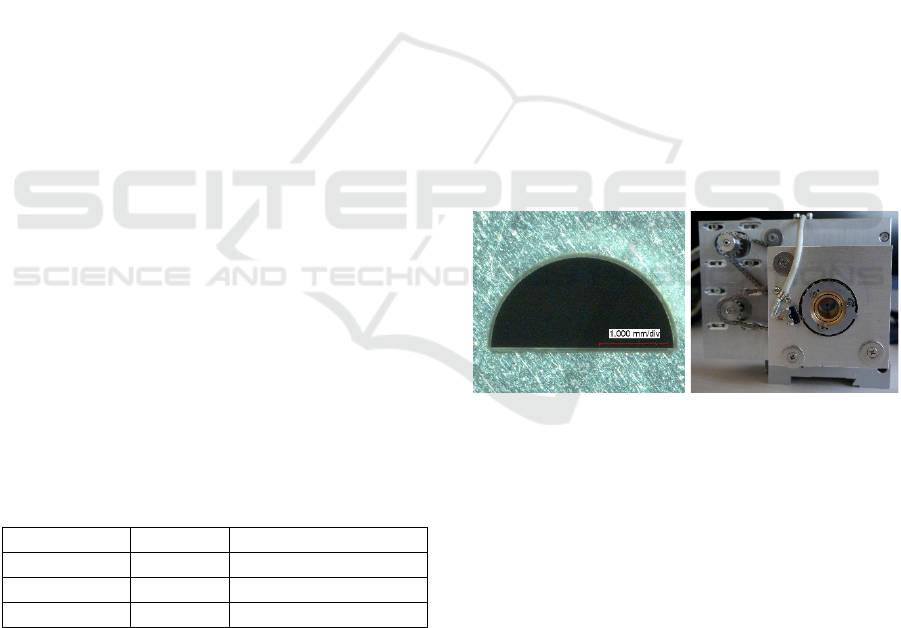
particular in rotation direction. This can be realized
by a combination of two semi-circular masks, which
are placed in a row. A sample is shown in Figure
1.
For this, a mask rotation system was developed. This
system consists of two rotary axis. Both masks can be
rotated independently by separate drives. The system
is shown in Figure 1.
Figure 1 and Figure 2: Semi-circular mask in tantalum-foil
for the fabrication of SPPs with a diameter of 100 µm (l.)
and developed double rotation system with two servo drives
for independent and separate movement of the masks (r.).
The micro structuring process starts with the cal-
culation of the sector angle and the step angle from
the topological charge (TC), which represents the
number of 2π phase jumps within the structure. Fur-
thermore, the number of levels N
i
defines the step an-
gle of the target structure. The masks are in congruent
position after the referencing of the system. Follow-
ing, one of the masks is twisted toward the other until
the sector angle is reached. This position is the initial
state for the microstructuring of each sector, inde-
pendently from the sector angle. In consideration of
the TC, the orientation of the resulting mask changes
Fabrication of Micro Spiral Phase Plates in Fused Silica using F2-Laser Microstructuring
115
for each sector. Starting from this initial state, the sec-
tor angle is reduced by the step angle after every laser
pulse. This process is repeated until the number of re-
quired steps is reached. In this way the SPPs were fab-
ricated sector by sector. The process is realized in a
sequence of loops and can be influenced by the TC,
the level number and the laser pulse fluence. The lat-
ter defines the ablation depth per pulse, which defines
the vertical step size. One advantage of these tech-
nique is, that we are able to fabricate irregular SPPs.
However, a disadvantage is, that the topological
charge has to be at least two and the process is limited
by the resolution of the imaging system in general and
accuracy of the mechanic components as well. After
the fabrication, we removed the remained debris by
etching the sample 30 min in a 1.7 molar KOH solu-
tion, followed by 15 min ultrasonic cleaning.
3 RESULTS AND DISCUSSION
3.1 Geometrical Properties of the
Fabricated SPPs
The fabrication of SPPs in fused silica with different
TCs is possible by changing the number of sectors N
l
and the corresponding sector angle. For regular SPPs
the sector angle is an integer fractional part of 360 de-
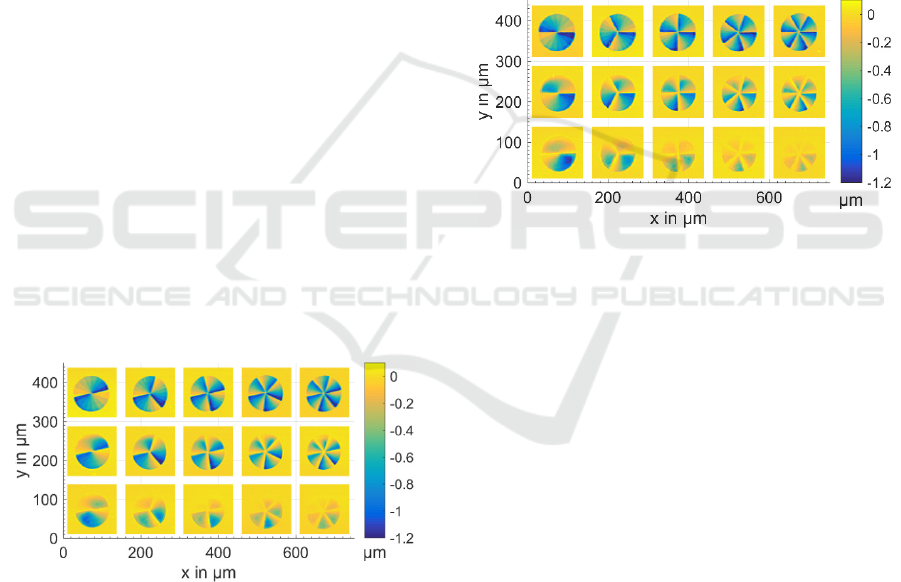
gree. A set of fabricated SPPs with different TCs and
level numbers are shown in Figure 3. As can be seen
in this Figure, the sectors of the SPPs in the upper row
are well fabricated.
Figure 3: Three dimensional micrographs (top view) of fab-
ricated SPPs in Corning 7980 with m = 1, a TC of 2, 3, 4, 5
and 6 (left to right) and a level number of 8, 16 and 32 (top
to bottom).
This is caused by the higher laser pulse fluence
and the appropriate ablation depth per pulse. The
SPPs in the middle and lower row got an uneven
depth within the sectors. The Reason for this is the
inhomogeneity of the energy distribution of the laser
beam. The used laser system is currently not in tune.
Because of a low damage threshold of some optical
components, the homogenizer is de-adjusted. Due to
this, the energy distribution of the laser beam is
slightly in-homogenous. The fabrication of SPPs with
a higher level number requires a lower step size and
thereby a lower laser pulse fluence. The fabrication of
SPPs with 32 levels requires an ablation depth per
pulse of 24.27 nm. Due to this, the used laser pulse
fluence is H = 0.77 J/cm², which is just a little more
than the ablation threshold fluence of
H
th
= 0.56 J/cm² of the material. Because of this, the
error of the ablation depth within the ablation area in-
crease and summed up by the number of pulses. In
this way, the inhomogeneity of the laser beam is
transferred to the surface and in particular to the mi-
crostructure. Nevertheless, it is possible to fabricate
left-handed SPPs (see Figure 4).
Figure 4: Three dimensional micrographs (top view) of fab-
ricated SPPs in Corning 7980 with m = -1, a TC of 2, 3, 4,
5 and 6 (left to right) and a level number of 8, 16 and 32
(top to bottom).
In this case, the calculations and starting condi-
tions are the same. However, the motion of the axis
were interchanged and the feed direction is inverted.
As a result, the microstructuring depth increase in the
counter clockwise direction, as can be seen. In Fig-
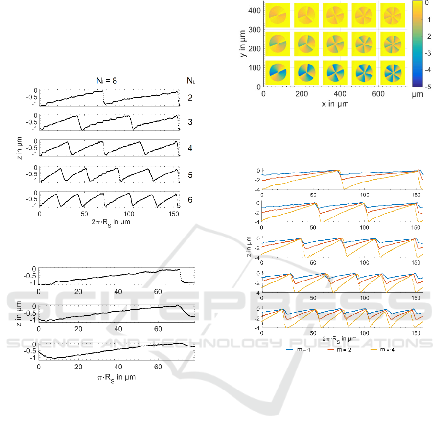
ure 5 the circular profile sections of the 8-level SPPs
are shown. The radius of the circular section was set
to R
s
= 25 µm. As can be seen, the single slope within
one SPP is nearly equal. In general the microstructur-
ing depth is in the range of 900 nm which is slightly
more than the required 776.72 nm. Furthermore, the
last step is significantly deeper than the previous
steps.
The reason for this is the accumulation of radia-
tion, which is reflected at the steep edge of the struc-
ture. Moreover, the lateral step size become smaller
by increasing the TC. An increase of this lead to a re-
duction of the sector angle as well as the step angle
and the corresponding lateral step size. Furthermore,
it can be seen that the arc length of the sectors are not
equal. The reason for this, is possibly a malfunction
PHOTOPTICS 2020 - 8th International Conference on Photonics, Optics and Laser Technology
116
of the rotation system. This problem can maybe
solved by some constructive changes. The compari-
son of one sector of an 8-, 16- and 32-level SPPs with
a topological charge of 2 shows the influence of the
level number and the required reduction of the verti-
cal step size (see Figure 6).
Figure 5: Circular profile section of the 8 level SPPs with
different TCs.
Figure 6: Circular profile section of one sector of an 8-, 16-
and 32-level SPP with a TC of 2.
The increase of the numbers of levels once more
lead to the reduction of the lateral step size. Due to
this the profile section of the 32-level SPP is more
continuous than the section of the 8- and 16-level
SPPs. In consideration of the radial dependencies of
this, it is not possible to fabricate a complete contin-
uous surface with this technique. Furthermore, it can
be seen that the steep edge of the structure also be-
come flattened by increasing the number of levels.
Thereby the gained efficiency is affected by geomet-
rical inaccuracies. One option to avoid these, is to in-
crease the modulation depth. The SPPs, which are
shown in Figure 7, were fabricated with a laser pulse
fluence of 1.97 J/cm².
Figure 7: Three dimensional micrographs (top view) of fab-
ricated SPPs in Corning 7980 with a m of -1, -2 and -4, a
TC of 2, 3, 4, 5 and 6 (left to right), a level number of 8, 16
and 32 (top to bottom) and constant vertical step size.
Figure 8: Circular profile section of the 8, 16 and 32 level
SPPs with a modulation depths m of -1, -2 and -4.
To increase the modulation depth, the number of lev-
els were increased only. The SPPs which were shown
in Figure 7 are left handed, with an m of -1 (upper
row), -2 (middle row) and -4 (lower row). The in-
crease of the OAM by increasing the level number,
lead to a surface profile with a more continuous
course, as can be seen in Figure 8.
3.2 SPPs with Lens Term
To show further opportunities of this fabrication tech-
nique, we calculated some different kinds of masks.
One calculated mask pair is shown in Figure 9. Re-
garding to this, the left mask is the semi-static mask,
which defines a constant sector angle. Because of the
asymmetric geometry of the rotation mask (right), it
is not possible to influence the sector angle like using
the semi-circular masks. At the beginning of the pro-
cess the masks have to be in congruent position with
Fabrication of Micro Spiral Phase Plates in Fused Silica using F2-Laser Microstructuring
117
regard to their rotation center and lower edges. This
kind of masks enables the fabrication of SPPs with an
additional radius of curvature (ROC) and straight sec-
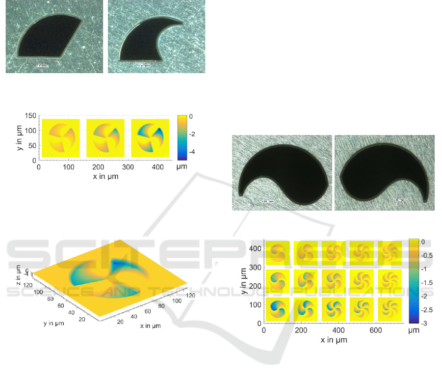
tor edges, as can be seen in Figure 10.
Figure 9: Semi-static mask (left) and rotary mask (right) for
SPP fabrication with additional radius of curvature (ROC).
Figure 10: Three dimensional micrographs (top view) of
three fabricated SPPs in Corning 7980 with an m of -1, -2
and -4, a TC of 3 and a level number of 8, 16 and 32 (left to
right).
Figure 11: Three dimensional micrograph of a SPP with ad-
ditional ROC.
But this combination got also a big disadvantage.
It is not possible to get the whole sector structured, as
can be seen in Figure 11. To solve this problem, the
micro structuring process has to be divided in two
processes.
In a first sequence one sector of the SPP has to be
fabricated like described in the previous chapter. In a
second sequence, the fabricated staircase structure
has to be structured again, using the corresponding
mask geometry for lens fabrication. The calculation
method for this and the parameter dependencies were
subject of previous investigations. For this setup,
there are different ways to solve this problem. The
first is to reduce the sector angle of the semi-static
mask to the half of the rotation mask. The second is
to enlarge the mask aperture angle of the rotation
mask to the twice angle of the semi-static mask. One
of these configurations allows the described proce-
dure. This can lead to a microstructuring process
where the level number, the OAM and the ROC can
be influenced independently. Only the TC is given by
the mask itself. The third method is to calculate two
nearly identical masks with curved radial edges of the
sector. But the one mask has to be reversed to the
other because they are placed in opposite of each
other. Due to the curved edges of the mask, the edges
of the sectors of the SPPs become also curved. The
advantages of this configuration are the same like the
semi-circular masks. But the ROC is not inde-
pendently adjustable with regard to the level number,
the handedness and also the vertical step size. How-
ever, we calculated two semi-circular masks with de-
fined curved sector edges, as can be seen in Figure 12.
Figure 12: Set of semi-circular masks with curved edges.
Figure 13: Three dimensional micrographs (top view) of
SPPs with an m of -1, -2 and -4 (top to bottom), an addi-
tional ROC, curved sector edges and different level num-
bers (8, 16 and 32 from top to bottom).
And as intended, using these masks lead to curved
sector edges. This is shown in Figure 13. The calcu-
lated ROCs of the structures are in the range of 1 to
16 mm, depending on the TC and the level number.
But we are currently not able to measure the ROC of
these structures. For this we need to develop a special
evaluation algorithm which separates the spherical
from the helical structural percentage. This should be
done in consideration of some well selected and de-
fined boundary conditions, which we did not defined
yet. Furthermore, we have to take some fabrication
defects into account, which we cannot separate from
the structure easily.
PHOTOPTICS 2020 - 8th International Conference on Photonics, Optics and Laser Technology
118
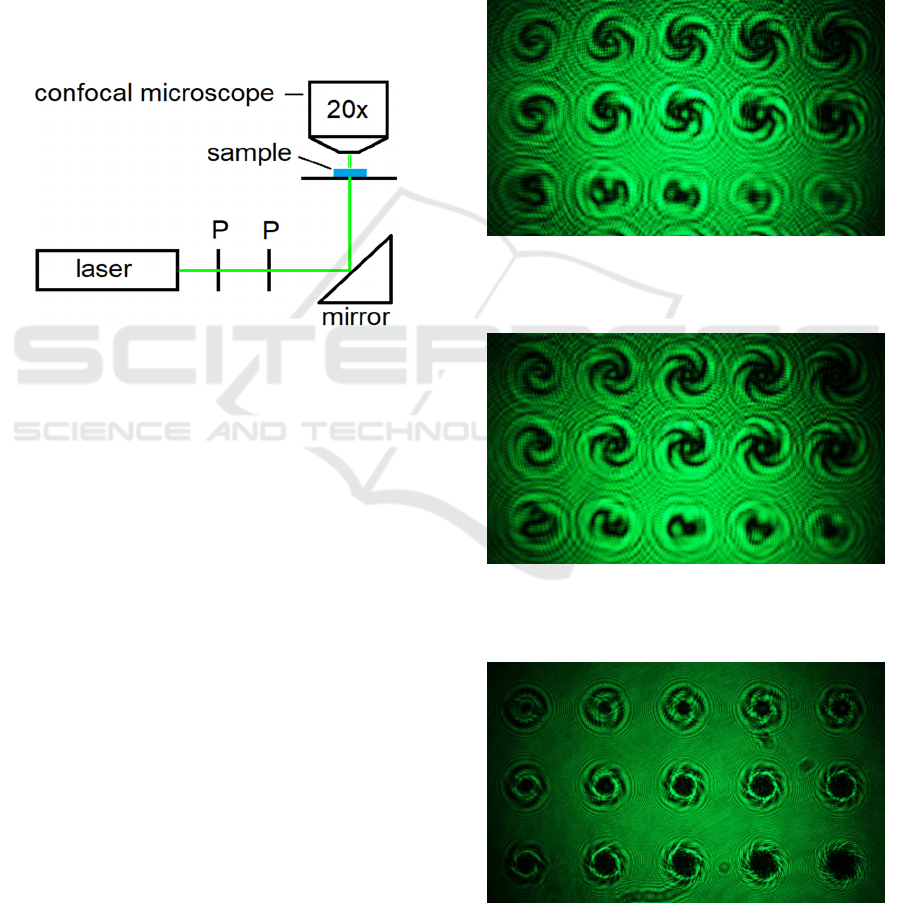
3.3 Testing the Optical Function
To prove the optical function of these elements, we
set up a simple measurement system, where the sam-
ple is illuminated by a frequency doubled Nd:YAG
laser. The intensity of the laser beam can be adjusted
by two polarizers (P). For the detection of the radia-
tion, we used a confocal microscope. A schematic il-
lustration of the measurement setup is shown in
Figure
14. With this we are able to measure the relative in-
tensity distribution of a set of SPPs in a defined plane
behind the sample. Because of some geometrical lim-
itations, we can capture the diffraction image in a
maximum distance of 3 mm.
Figure 14: Illustration of the measurement setup.
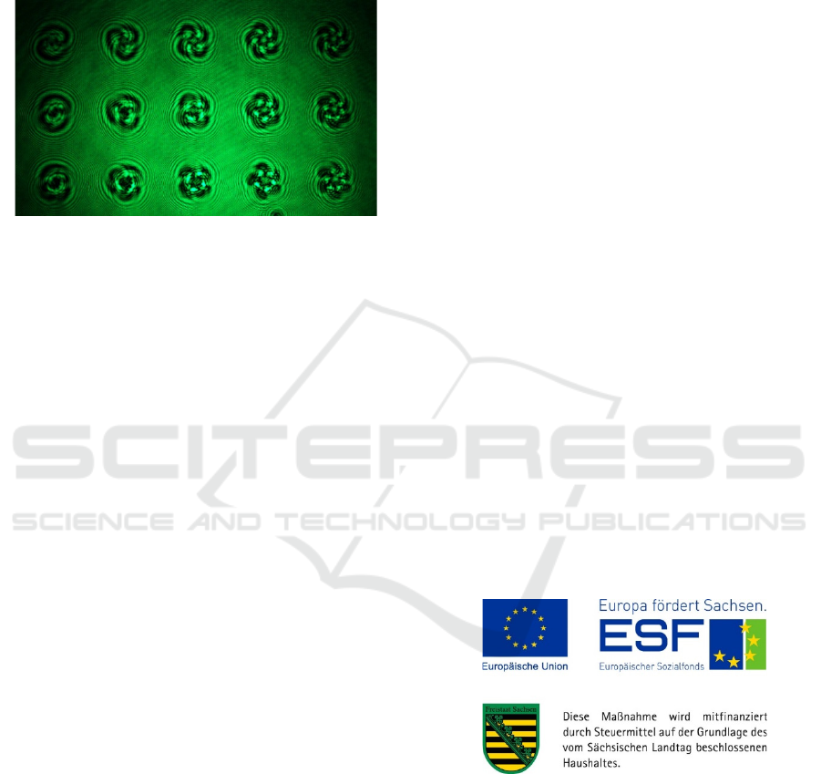
As can be seen in Figure
15 and Figure 16 the
number of intensity maxima increase with the number
of TCs. The distributions which are generated by
SPPs in the lower rows, are very different. This is
caused by the fabrication errors, which were dis-
cussed in chapter 3.1. Moreover, there are some
smaller intensity maxima in the center of the shown
distributions in the upper and the middle row. The
reason for this is the unstructured area in the center of
the SPPs. This is mainly a result of the limited reso-
lution of the imaging system of the micro machining
station in combination with adjusting and imaging er-
rors. Furthermore, it can be seen that the intensity dis-
tributions of the SPPs with the same configuration but
different handedness is the inverted of each other.
However, with this measurement setup it is not
possible to see a significant influence of the level
number. Furthermore, there are interfering effects be-
tween adjacent distributions. To prevent this, the spot
of the laser beam has to be reduced. If this is not suf-
ficient a pinhole could be placed on axis to the SPP.
The relation of the pinhole and beam diameter should
be selected in a right way, to avoid any diffraction ef-
fects. In comparison to the level number, the influ-
ence of the modulation depth can be seen clearly. The
diffraction image in Figure 17 is generated by the
SPPs which are shown in Figure 7. The increase of
the modulation depth lead to a circular formation of
the intensity maxima. Moreover, the maxima are lat-
erally reduced in radial direction. The diffraction im-
ages in the lower row show also a subdivision of the
ring distribution. The reason for this could be the in-
teraction of the lateral step size (and corresponding
level number) and the TC. In this case, the higher
level number could lead to a very small lateral step
size. These steps may act as a circular phase grating,
in superposition with the helical phase.
Figure 15: Confocal microscope image of the intensity dis-
tribution 3 mm above the SPPs are shown in Figure 3
(OAM
-
).
Figure 16: Confocal microscope image of the intensity dis-
tribution 3 mm above the SPPs are shown in Figure 4
(OAM
+
).
Figure 17: Confocal microscope image of the intensity dis-
tribution 0.49 mm above the SPPs with different modula-
tion depth.
Fabrication of Micro Spiral Phase Plates in Fused Silica using F2-Laser Microstructuring
119
In addition, the SPPs which were fabricated with
the curved semi-circular masks were also optically
examined. As can be seen in
Figure 18, the curved
steps and sectors lead to a further reduction of the
maxima size in rotation direction.
Figure 18: Intensity distribution of transmitting radiation
through SPPs 0.49 mm above, with different modulation
depth and additional ROC (SPPs shown in Figure 13).
As a result, the optical response of the SPPs in-
cludes a defined number of intensity maxima depend-
ing on the TC. The ROC decrease by the increase of
the TC and the level number. This could lead to a re-
duction of the maxima size and thereby an increase of
the intensity too. Like in the previous investigations,
the influence of the level number is not apparent. This
could be solved by upgrading the measurement sys-
tem for single SPP characterization with optimized
measurement conditions.
4 CONCLUSIONS
The fabrication of SPPs with different TCs, level
numbers, handedness and modulation depths is possi-
ble using the fluorine laser microstructuring tech-
nique. For this, a double mask rotation system was
developed and installed.
The fabrication of simple SPPs can be done using
two semi-circular masks. Furthermore, these allows
the fabrication of SPPs with different configurations
by changing the process and programming parame-
ters. This enables the fabrication of SPPs with a TC
of 2 to 6. The number of intensity maxima within the
optical response of the SPPs is equal to the TC. In
general, the fabrication of SPPs with an irregular TC
is possible. Due to some little inaccuracies in the arc
length of the sectors, the rotation system should be
optimized.
An increase of the level number lead to a more
continuous surface profile and enhance the efficiency
of the SPPs but requires a very low laser pulse fluence
for a 2π modulation depth. As a result, the slightly in-
homogeneous energy distribution of the laser beam is
transferred into the microstructure. This affect the op-
tical function of the SPPs. To solve this problem the
modulation depth can be increased. But this also got
an influence on the OAM and lead to the reduction of
the size of the intensity maxima in radial direction.
In addition to this, the SPPs can be fabricated in-
cluding a ROC in two different ways. The first is to
calculate a set of masks for the fabrication of a de-
fined SPP. The other way is to calculate two semi-
circular masks with curved edges. Using the latter
lead to a more flexible process in comparison to the
first. But for this the ROC cannot be influenced inde-
pendently from the other parameters. However, an ad-
ditional ROC lead to a further reduction of the size of
the intensity maxima. The influence of the step size
should be the subject of further investigations and
supported by some theoretical studies. For the im-
provement of the optical characterization, the meas-
urement system should be improved too.
Moreover, we want to build up an optical link us-
ing some lenses first, followed by using a fiber as a
transfer medium. Depending on the results, further in-
vestigations will be done in the field of OAM multi-
plexing using integrated optics.
ACKNOWLEDGEMENTS
The authors gratefully acknowledge the financial sup-
port of the present work by the European Union and
the Free State of Saxony.
REFERENCES
Allen, L., Beijersbergen, M.W., Spreeuw, R.J.C. and
Woerdman, J.P. (1992). Orbital angular momentum of
light and the transformation of Laguerre-Gaussian laser
modes. In Physical Review A, 45(11), pp. 8185-8189.
Allan, L. and Padgett, M. (2011). The Orbital Angular Mo-
mentum of Light: An Introduction, In: Twisted Photons,
eds. Torres J.P and Torner L., pp. 1-12.
PHOTOPTICS 2020 - 8th International Conference on Photonics, Optics and Laser Technology
120

Bozinivic, N., Yue, Y., Ren, Y., Tur, M., Kristensen, P.,
Huang, H., Willner, A.E. and Ramachandran, S. (2013).
Terrabit-Scale Orbital Angular Momentum Mode Divi-
sion Multiplexing in Fibers. In Science, 340 (6140), pp.
1545-1548.
Buettner, S., Pfeifer, M., and Weissmantel, S. (2019). Man-
ufacturing of Cylindrical Micro Lenses and Micro Lens
Arrays in Fused Silica and Borosilicate Glass using F
2
-
Laser Microstructuring. 7th International Conference
on Photonics, Optics and Laser Technology.
Kasztelanic, R., Kujawa, I., Stępień, R., Haraśny, K., Pysz,
D. and Buczyński, R. (2013). Molding of soft glass re-
fraction mini lens with hot embossing process for
broadband infrared transmission systems. In Infrared
Physics & Technology, 61, pp. 299-305.
Neitz, M., Wöhrmann, M., Zhang, R., Fikry, M., Marx, S.
and Schröder, H. (2017). Design and Demonstration of
a Photonic Integrated Glass Interposer for Mid-Board-
Optical Engines, 67
th
Electronic Components and Tech-
nology Conference.
O’Shea, D.C., Suleski, Th.J., Kathman, A.D. and Prather,
D.W. (2004). Diffractive Optics. Design, Fabrication,
and Test. Bellingham, Washington USA: SPIE, pp. .
Pfeifer, M., Büettner, S., Zhang, R., Serbay, M. and
Weißmantel, S. (2015). F2-Lasermikrostrukturierung
von Mikro-Fresnel-Linsen, In Journal of the University
of Applied Sciences Mittweida, pp. 127-130.
Pfeifer, M., Jahn, F., Kratsch, A., Steiger, B. and
Weissmantel, S. 2014. F
2
-Laser Microfabrication of
Diffractive Optical Elements, 2nd International
Conference on Photonics, Optics and Laser
Technology.
Pfeifer, M., Weissmantel, S. and Reisse, G. 2013. Direct
laser fabrication of blaze gratings in fused silica. In
Applied Physics A 112, pp. 61-64.
Qiu, J., Li, M., Ye, H., Yang, C., and Shi, C. (2018).
Fabrication of high fill factor cylindrical microlens
array with isolated thermal reflow. In Applied Optics,
57(25), pp. 7296-7302.
Richardson, D. J. (2010). Filling the Light Pipe. In Science,
330 (6002), pp. 327-328.
Xie, Z., Gao, S., Lei, T., Feng, S., Zhang, Y., Li, F. Zhang,
J., Li, Z. and Yuan, X. (2018). Integrated
(de)multiplexer for orbital angular momentum fiber
communication. In Photonics Research, 6 (7), pp. 743-
749.
Xing, J., Rong, W., Sun, D., Wang, L. and Sun, L. (2016).
Extrusion printing for fabrication of spherical and
cylindrical microlens arrays. In Applied optics, 55 (25),
pp. 6947–6952.
Fabrication of Micro Spiral Phase Plates in Fused Silica using F2-Laser Microstructuring
121
