
Multi-view Data Capture using Edge-synchronised Mobiles
Matteo Bortolon, Paul Chippendale, Stefano Messelodi and Fabio Poiesi
Fondazione Bruno Kessler, Trento, Italy
Keywords:
Synchronisation, Free-viewpoint Video, Edge Computing, Augmented Reality, ARCloud.
Abstract:
Multi-view data capture permits free-viewpoint video (FVV) content creation. To this end, several users
must capture video streams, calibrated in both time and pose, framing the same object/scene, from different
viewpoints. New-generation network architectures (e.g. 5G) promise lower latency and larger bandwidth
connections supported by powerful edge computing, properties that seem ideal for reliable FVV capture. We
have explored this possibility, aiming to remove the need for bespoke synchronisation hardware when capturing
a scene from multiple viewpoints, making it possible through off-the-shelf mobiles. We propose a novel and
scalable data capture architecture that exploits edge resources to synchronise and harvest frame captures. We
have designed an edge computing unit that supervises the relaying of timing triggers to and from multiple
mobiles, in addition to synchronising frame harvesting. We empirically show the benefits of our edge computing
unit by analysing latencies and show the quality of 3D reconstruction outputs against an alternative and popular
centralised solution based on Unity3D.
1 INTRODUCTION
Immersive computing represents the next step in hu-
man interactions, with digital content that looks and
feels as if it is physically in the same room as you.
The potential for immersive digital content impacts
upon entertainment, advertising, gaming, mobile tele-
presence and tourism (Shi et al., 2015; Jiang and Liu,
2017; Elbamby et al., 2018; Rematas et al., 2018;
Park et al., 2018; Qiao et al., 2019). But for immer-
sive computing to become mainstream, a vast amount
of easy-to-create free-viewpoint video (FVV) content
will be needed. The production of 3D digital objects
inside a real-world space is almost considered a solved
problem (Schonberger and Frahm, 2016), but doing
the same for FVV is still a challenge (Richardt et al.,
2016). This mainly because FVVs require the tempo-
ral capturing of dynamic objects from different, and
calibrated viewpoints (Guillemaut and Hilton, 2011;
Mustafa and Hilton, 2017). Synchronisation across
viewpoints dramatically reduces reconstruction arte-
facts in FVVs (Vo et al., 2016). For controlled se-
tups, frame-level synchronisation can be achieved us-
ing shutter-synchronised cameras (Mustafa and Hilton,
2017), however this is impractical in uncontrolled en-
vironments with conventional mobiles. Moreover, mo-
bile pose estimation (i.e. position and orientation) with
respect to a global coordinate system is necessary for
content integration. This can be achieved using frame-
by-frame Structure from Motion (SfM) (Schonberger
and Frahm, 2016) or Simultaneous Localisation And
Mapping (SLAM) (Mur-Artal et al., 2015). The latter
has shown to be effective for collaborative Augmented
Reality though the ARCloud (ARCore Anchors, 2019).
ARCore Anchors
1
are targeted at AR multiplayer gam-
ing, but we experimentally tested that they are not
yet ready for FVV production as is, i.e. relative pose
estimation is not sufficiently accurate for 3D recon-
struction. As per our knowledge a flexible and scalable
solution for synchronised calibrated data capture de-
ployable on conventional mobiles does yet not exist.
As FVVs require huge data transmissions, throughput
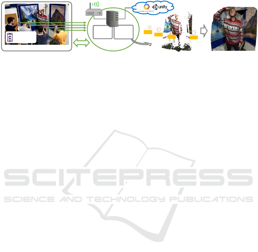
is another challenge for immersive computing. Fig. 1
shows four people recording a person with their mo-
biles. The measured throughput in this setup was about
52Mbps with frames captured at 10Hz, with a resolu-
tion of 640
×
480 pixels and encoded in JPEG. Note
that only a portion of the recorded person was covered.
For a more complete, 360-degree coverage, several
more mobiles would be needed. With the introduc-
tion of new wireless architectures that target high-data
throughput and low latency, such as Multi-access Edge
Computing (MEC), device-to-device communications
and network slicing in 5G networks, scalable com-
munication mechanisms that are appropriate for the
1
The AR Anchor is a rigid transformation from local to
a global coordinate system.
730
Bortolon, M., Chippendale, P., Messelodi, S. and Poiesi, F.
Multi-view Data Capture using Edge-synchronised Mobiles.
DOI: 10.5220/0008971807300740
In Proceedings of the 15th International Joint Conference on Computer Vision, Imaging and Computer Graphics Theory and Applications (VISIGRAPP 2020) - Volume 5: VISAPP, pages
730-740
ISBN: 978-989-758-402-2; ISSN: 2184-4321
Copyright
c
2022 by SCITEPRESS – Science and Technology Publications, Lda. All rights reserved
frame
stream
pose estimation
frame capture
edge processing
recording moving person
sync
data
relaying
4D
recon
cam 3
cam 2
cam 1
cam 4
meshing
texturing
ARCloud
Figure 1: Multi-view data captures for free-viewpoint video creation generates large data throughput, and requires synchronised
and calibrated cameras. Our solution offloads computations from mobiles and the cloud to the edge, handling synchronisation
and image processing more efficiently. Moving processing closer to the user improves performance and fosters scalability.
deployment of immersive content on consumer de-
vices are key (Shi et al., 2016; Qiao et al., 2019). Hy-
brid cloud/fog/edge solutions will ensure that users get
low-lag feedback as well as the possibility to offload
computationally intensive tasks.
In this paper, we present a system that harvests data
generated from multiple-handheld mobiles at the edge
instead of harvesting it in the cloud. This promotes
scalability, lower latency and facilitates synchronisa-
tion. Our implementation consists of a server, namely
Edge Relay, that handles communications across mo-
biles and a Data Manager that harvests the content
captured by the mobiles. We handle synchronisation
through a relay server because, as opposed to a peer-
to-peer one, relay servers can effectively reduce band-
width usage and improve connection quality (Hu et al.,
2016). Although relay servers may lead to increases
of network latency, peer-to-peer connection may be
ineffective because when mobiles are within differ-
ent networks (e.g. different operators in 5G networks),
they cannot retrieve their respective IP address due
to Network Address Translation (NAT). Moreover, to
mitigate the latency problem, we designed a latency
compensation strategy, that we empirically tested to
be effective when the network conditions are fairly
stable. We developed an app that each mobile uses
to capture frames and estimate pose with respect to a
global coordinate system through ARCore (ARCore,
2019). As the relative poses from ARCore are not
accurate enough for FVV, we refine them using SfM
(Schonberger and Frahm, 2016). To summarise, the
key contributions of our system are (i) the protocols we
have designed to allow users under different networks
(or operators) to join the same data capture session, (ii)
the integration of a latency compensation mechanism
to mitigate the communication delay among devices,
and (iii) the integration of these modules with a SLAM
framework to estimate mobile pose in real time and to
globally localise mobiles in an environment through
the ARCloud. As per our knowledge, this is the first
proof-of-concept, decentralised system for synchro-
nised multi-view data capture usable for FVV content
creation. We have carried out a thorough experimental
analysis by jointly assessing latency and temporal 3D
reconstruction. We have compared results against an
alternative and popular centralised solution based on
Unity3D (Unity3D Multiplayer Service, 2019).
2 RELATED WORK
Low Latency Immersive Computing.
To foster im-
mersive interactions between multiple users in aug-
mented spaces, low-latency computing and commu-
nications must be supported (Yahyavi and Kemme,
2013). Although mobiles are the ideal medium to de-
liver immersive experiences, they have finite resources
for complex visual scene understanding, reasoning
and graphical tasks, hence computational offloading
is preferred for demanding and low-latency interac-
tions. Fog and edge computing, soon to be mainstream
thanks to 5G, will be one of the key enablers. Thank-
fully, not all immersive computing tasks (e.g. scene
understanding, gesture recognition, volumetric recon-
struction, illumination estimation, occlusion reasoning,
rendering, collaborative interaction sharing) have the
same time-critical nature. (Chen et al., 2016; Zhang
et al., 2018) showed that scene understanding via ob-
ject classification could be performed at a rate of sev-
eral times per minute by outsourcing computations
to the cloud. (Zhang et al., 2018) showed how an
optimised image retrieval pipeline for a mobile AR
application can be created by exploiting fog comput-
ing, reducing data transfer latency up to five times
compared to cloud computing. (Sukhmani et al., 2019)
analysed the concept of dynamic content caching for
mobiles, i.e. what to cache and where, and they illus-
trated that a dramatic performance increase could be
obtained by devising appropriate task offloading strate-
gies. (Bastug et al., 2017) showed how a pro-active
content request strategy could effectively be used to
predict content before it was actually requested, thus
reducing immersive experience latency, at the cost of
increased data overhead. In the cases of FVV, which is
very sensitive to synchronisation issues, communica-
Multi-view Data Capture using Edge-synchronised Mobiles
731
tions must be executed as close to the user as possible
to reduce lag. Solutions to address the problem can be
hardware or software based. Hardware-based solutions
include timecode synchronisation with or without gen-
lock (Kim et al., 2012; Wu et al., 2008), and Wireless
Precision Time Protocol (Garg et al., 2018). Hardware
based solutions is not our target as they require impor-
tant modifications to the communication infrastructure.
Software-based solutions are often based on the Net-
work Time Protocol (NTP), instructing devices in a
session to acquire frames at prearranged time intervals
and then attempt to compensate/anticipate for delays
(Latimer et al., 2015). Cameras can share timers that
are updated by a host camera (Wang et al., 2015). Al-
ternatively, errors in temporal frame alignment have
been addressed using spatio-temporal bundle adjust-
ment, in an offline post-processing phase (Vo et al.,
2016). However, this type of post-alignment also in-
curs a high computational overhead, as well as adding
more latency to the creation and consumption of FVV
reconstructions. Although NTP approaches are simple
to implement, they are unaware of situational-context.
Hence, the way in which clients are instructed to cap-
ture images in a session is totally disconnected from
scene activity, hence they are unable to optimise ac-
quisition rates either locally or globally, prohibiting
optimisation techniques such as (Poiesi et al., 2017),
that aim to save bandwidth and maximise output qual-
ity. Our solution operates online and is aimed at de-
centralising synchronisation supervision, thus is more
appropriate for resource-efficient, dynamic-scene cap-
ture.
Free-viewpoint Video Production.
Free-viewpoint
(volumetric or 4D) videos can be created either through
the synchronised capturing of objects from different
viewpoints (Guillemaut and Hilton, 2011; Mustafa
and Hilton, 2017) or with Convolutional Neural Net-
works (CNN) (Rematas et al., 2018) that estimate
unseen content. The former strategy needs camera
poses to be estimated/known for each frame, using
approaches like SLAM (Zou and Tan, 2013) or by hav-
ing hardware calibrated camera networks (Mustafa and
Hilton, 2017). Typically, estimated poses lead to less-
accurate reconstructions (Richardt et al., 2016), when
compared to calibrated setups (Mustafa and Hilton,
2017). Converserly, CNN-based strategies do not
need camera poses, but instead need synthetic training
data of 3D objects extracted, for example, from video
games or Youtube videos (Rematas et al., 2018) as they
need to estimate unobserved data. Traditional FVV
(i.e. non-CNN) approaches can be based on shape-
from-silhouette (SFS) (Guillemaut and Hilton, 2011),
shape-from-photoconsistency (SFP) (Slabaugh et al.,
2001), multi-view stereo (MVS) (Richardt et al., 2016)
Cloud
Google
Cloud Platform
Unity3D
Match Making
Router Switch
Router
Edge
Edge Relay
Server
Data
Manager
Local Network
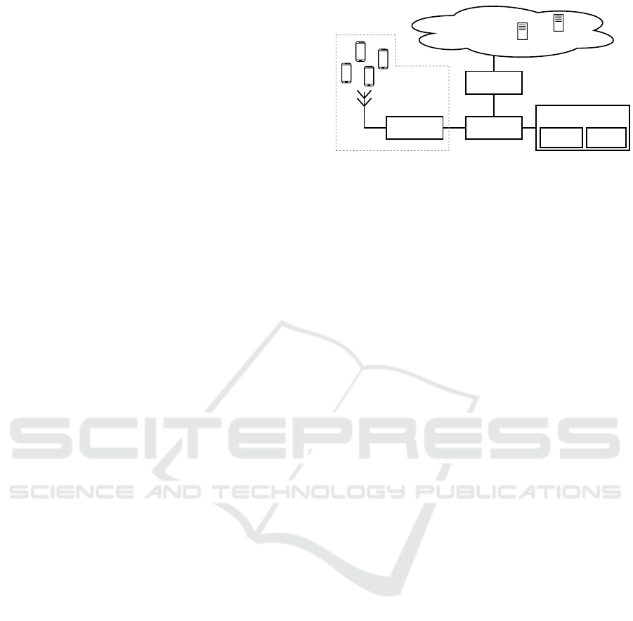
Figure 2: Block diagram of our edge-based architecture.
Mobiles are connected to the same local network (e.g. WiFi
or 5G). When they perform a FVV capture, data relaying and
processing is performed on the edge, ensuring low-latency
and synchronised frame capture.
or deformable models (DM) (Huang et al., 2014). SFS
methods aim to create 3D volumes (or visual hulls)
from the intersections of visual cones formed by 2D
outlines (silhouettes) of objects visible from multiple
views. SFP methods create volumes by assigning in-
tensity values to voxels (or volumetric pixels) based
on pixel-colour consistencies across images. MVS
methods create dense point clouds by merging the re-
sults of multiple depth-maps computed from multiple
views. DM methods try to fit known reference 3D-
models to visual observations, e.g. 2D silhouettes or
3D point clouds. All these methods need frame-level
synchronised cameras. (Vo et al., 2016) proposed a
spatio-temporal bundle adjustment algorithm to jointly
calibrate and synchronise cameras. Because it is a
computationally costly algorithm, it is desirable to ini-
tialise it with “good” initial camera poses and synchro-
nised frames. Amongst these methods, MVS produces
reconstructions that are geometrically more accurate
than the other alternatives, albeit at a higher compu-
tational cost. Approaches like SFS and SFP are more
suitable for online applications as they are fast, but
outputs have less definition.
3 DATA CAPTURING OVERVIEW
Our system carries out synchronisation and data cap-
ture at the edge, and uses cloud services for the session
initialisation. The edge hosts two applications: an
Edge Relay and a Data Manager. Services used in
the cloud are a Unity3D Match Making server and
the Google Cloud Platform. Fig. 2 shows the block
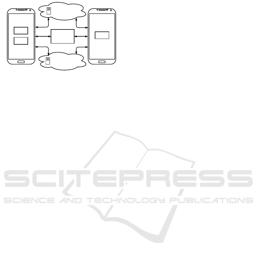
diagram of our system. Fig. 3 details the session setup.
When a group of users want to initiate a multi-view
capture, they must connect their mobiles to a wireless
network via WiFi or 5G, and then open our frame-
capture app. One user, designated the session host,
creates a new session in the app. This sends a request
VISAPP 2020 - 15th International Conference on Computer Vision Theory and Applications
732
Google Cloud
Platform
Unity3D
Match Making
Edge Relay
Server
Client
Host
Client
(a)
(b)
(c)
(d)
(e)
(f)
Figure 3: Session setup procedure. Description of the steps
can be found in text.
to the Match Making server (Unity3D MatchMaking,
2019) to create an acquisition session (a). This request
includes the IP address of the host as seen from the
Edge Relay. The Match Making server adds this ses-
sion to a list of active sessions, associating it with a
unique session ID. The Match Making server publi-
cises this session ID for others to join as clients. The
host device informs the Edge Relay that it is ready to
accept client devices (b). Client devices see the list
of active sessions from the Match Making server and
they choose one to join (c). When a client chooses
a session, they retrieve the session ID, the host’s IP
address from the Match Making server, and it uses
this information to connect to the Edge Relay (d). The
Edge Relay validates client connections by verifying
that the information provided is correct. When all
clients have joined a session, the Match Making server
is not used again.
Before starting the frame capture, (i) all users must
map their local surroundings in 3D using the app’s
built-in ARCore functionality, then (ii) the host mea-
sures the communication latency between itself and
the clients to inform the clients of the compensation
needed to handle network delays. Latency compen-
sation is explained in Sec. 4. 3D mapping involves
capturing sparse geometric features of the environment
(Cadena et al., 2016). Once mapping is complete, the
host user places an AR Anchor in the mapped scene to
define a common coordinate system for all devices (e).
This AR Anchor is uploaded by the host to the Google
Cloud Platform and then automatically downloaded
by clients through HTTPS (Belshe et al., 2015), or
the QUIC protocol by devices that support it (QUIC,
2019) (f). Finally, the capture session starts when the
host client presses ‘start’ on their app.
Snapshots, or captured frames, can be taken either
periodically (Knapitsch et al., 2017), or dynamically
based on scene content (Resch et al., 2015; Poiesi
et al., 2017). Frame captures based on scene content is
desirable because one can avoid excessive data traffic
when a scene is still and then capture fast dynamics
by increasing the rate when high activity is observed.
However, the latter is more challenging than the former
as it requires mobiles to perform on-board processing
and a decentralised mechanism to reliably relay syn-
chronisation signals. We designed our system to be
suitable for dynamic frame captures, hence we have
chosen to let the host mobile drive synchronisation,
rather than fixing the rate beforehand on an edge or
cloud server. To trigger the other mobiles to capture a
frame, the host sends a snapshot (or synchronisation)
trigger to the Edge Relay. Snapshot triggers instruct
mobiles in a session to capture frames. The Edge Re-
lay forwards triggers received, from the host, to all
clients, instructing them to capture frames and gen-
erate associated meta-data (e.g. mobile pose, camera
parameters). Captured frames and meta-data are mo-
mentarily buffered on the devices and then transmitted
to the Data Manager asynchronously. Without loss of
generality, the host uses an internal timer to take snap-
shots that expire every
C = 1/F
. A snapshot counter
is incremented each time the countdown expires and it
is used as unique identifier for each snapshot taken.
4 EDGE RELAY
Traditional architectures for creating multi-user expe-
riences are based on authoritative servers (Yahyavi
and Kemme, 2013), typically exploiting relay servers
(Unity3D Multiplayer Service, 2019; Photon, 2019).
An authoritative-server based system allows one of the
participants to be both a client and the host at the same
time, thus having the authority to manage the session
(Unity3D HLAPI, 2019). Our Edge Relay routes ses-
sion control messages from the host to the clients via
UDP, to avoid delays caused by flow-control systems
(e.g. TCP). The Edge Relay handles four different
types of messages: Start Relaying, Connect-to-Server,
Data and Disconnect Client.
The host makes a Start Relaying request to the
Edge Relay to begin a session. This request carries
the connection configuration (e.g. client disconnection
deadline, maximum packet size, host’s IP address and
port number), which is used as a verification mecha-
nism for all the clients to connect to the Edge Relay
(MLAPI Configuration, 2019). The verification is per-
formed through a cyclic redundancy check (CRC). If
the host is behind NAT, clients will not be able to re-
trieve its IP address nor the port number, hence they
will not be able to include them in the connection con-
figuration, and hence they will not pass the verification
stage. In order to mitigate this NAT-related issue, we
required the Edge Relay to communicate to the host
the IP address and port number with which the Edge
Multi-view Data Capture using Edge-synchronised Mobiles
733

Relay sees the host. This IP address can be the actual
IP of the host if the Edge Relay and host are within
the same local network, or the IP address of the router
(NAT) if host and Edge Relay are on different net-
works. After the host receives this information from
the Edge Relay, the host communicates host’s IP ad-
dress and port number to the Match Making server.
In this way, when the clients discover the session ID
from the Match Making server, they can retrieve the
host’s IP address and port number, and use them for
verification to connect to the Edge Relay.
When a client decides to join a session, the client
sends a Connect-to-Server request message to the Edge
Relay. This message contains the IP and port address
of the host, which the client retrieved from the Match
Making server. The Edge Relay checks to see if the
requested session associated to this IP address and port
is already hosted by a mobile. If it is, then the Edge
Relay adds this client to the list of session participants.
Data messages carry information from one device
to another in a session. When a data packet is re-
ceived by the Edge Relay it explores the header to
understand where the packet must be forwarded to:
either to specific devices or broadcast to all. We use
a data messaging system that involves two types of
messages: State Update packages or Remote Proce-
dure Calls (RPCs) (MLAPI Messaging System, 2019).
State Update packages are used to update elements
in the session and to propagate the information to all
participants, i.e. the AR Anchor, while RPCs are used
for control commands, i.e. synchronisation triggers
and the latency estimation mechanism. The RPC of
the synchronisation trigger carries the information of
the snapshot counter (Sec. 3).
A Disconnect Client message is exchanged when
a user exits the session. This message can be sent
by the client or by the Edge Relay. The Edge Relay
detects the exit of a client if a Keep-alive packet is
not received within a timeout. We set the Keep-alive
time at 100ms and disconnect timeout as 1.6s. Upon
disconnection of a client, the Edge Relay informs all
the other participants and removes this device from the
list of participants of the session.
5 FRAME CAPTURE APP
OPTIMISATIONS
To deal with latency variation and large throughput,
we have implemented two optimisation strategies.
The latency between client/host and the Edge Re-
lay can vary due to the distance between devices and
the antenna, network traffic, or interference with other
networks (Soret et al., 2014). A high latency can
negatively affect the geometric quality of the recon-
structed object, so it must be understood and com-
pensated for (Vo et al., 2016). To cope with network
latency issues, we have implemented a latency com-
pensation mechanism that uses Round Trip Time mea-
surements on the communication link between host
and clients. We model the latency measured between
devices to delay the capture of a frame upon the re-
ception of a synchronisation trigger for each device
independently. This enables the devices to capture
frames (nearly) synchronously. Specifically, during
the initialisation phase, the host builds a
N × M
ma-
trix
P
, where the element
p(i, j)
is the
j
-th measured
Round Trip Time (i.e. ping) between the host and
the
i
-th client.
N
is the number of clients and
M
is
the total number of ping measurements. The host
computes the average ping for each client, such as
¯p(i) =
1
M
∑
M
j=1
p(i, j)
, and extracts the maximum ping
as
ˆp = max({ ¯p(1),..., ¯p(N)})
. Then the
i
-th client cap-
tures the snapshot with a delay of
∆t
i
=
1
2
· ( ˆp − ¯p(i))
ms, whereas the host captures the snapshot with a
delay of ˆp ms.
Each time a client receives a synchronisation trig-
ger, it captures a frame, and the associated meta-data,
i.e. pose (with respect to the global coordinate system),
camera intrinsic parameters (i.e. focal length, principal
point), device identifier and snapshot counter. To ef-
fectively handle frame captures when synchronisation
triggers are received, we use two threads on the mo-
biles. Triggers are managed by the main thread, which
uses a scheduler to guarantee that a frame is captured
when the calculated delay
∆t
i
expires. Each captured
frame is passed to a second thread that encodes it into
a chosen format (e.g. JPEG) and enqueues it for trans-
mission to the Data Manager. If there is bandwidth
available over the communication channel, frames are
transmitted immediately, otherwise they are buffered.
In the next section we explain how the Data Manager
processes the received frames.
6 DATA MANAGER
The Data Manager is an application that resides on
the edge unit and functions independently from the
Edge Relay (Fig. 2). The communication between the
Data Manager and the participants is based on HTTP
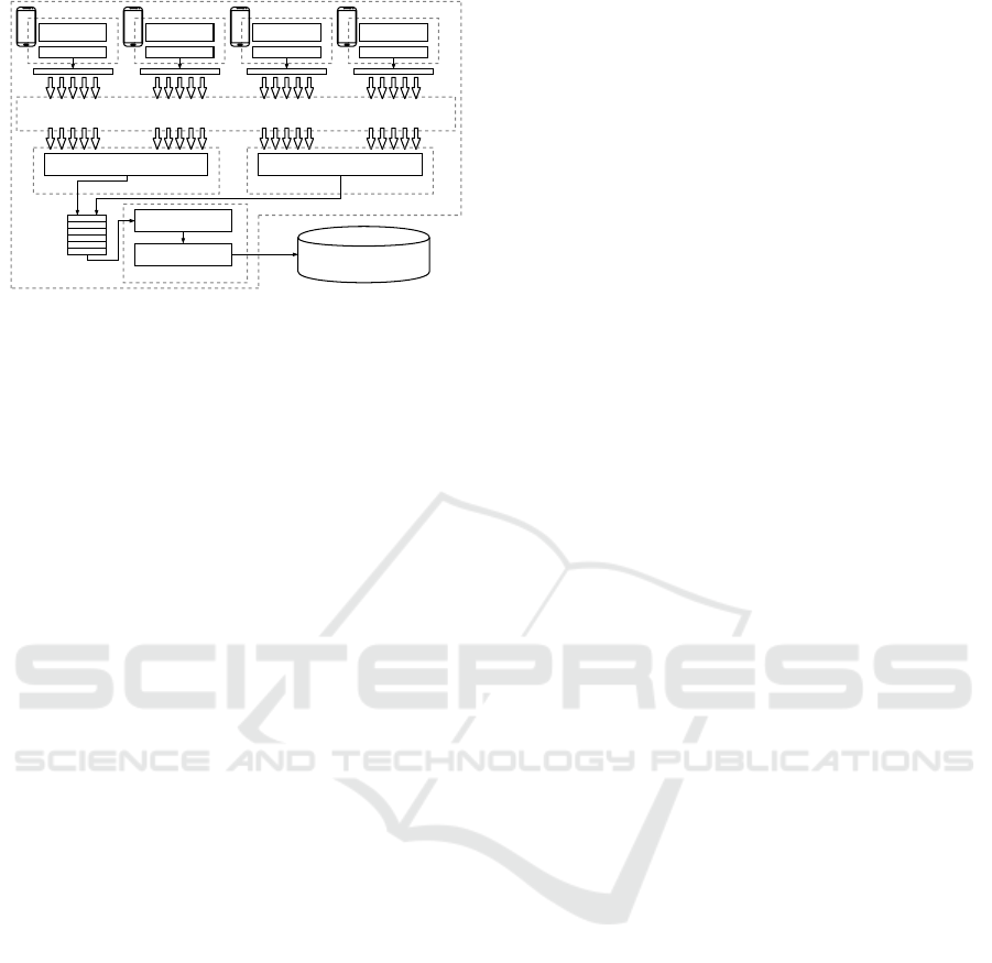
requests (Berners-Lee et al., 1996). Fig. 4 shows the
architecture of our Data Manager. The Data Manager’s
operation consists of three phases: Stream Initialisa-
tion, Frame Transmission and Stream End.
During the Stream Initialisation phase, the host
sends an initial HTTP request to the Data Manager
containing information about the number of devices
VISAPP 2020 - 15th International Conference on Computer Vision Theory and Applications
734
request handling thread
decoding
frames and
meta-data
frame
meta-data
...
...
...
...
HTTP
data manager
synchronised
queue
cpu core
frame
meta-data
frame
meta-data
frame
meta-data
post
requests
post
requests
post
requests
post
requests
request handling thread
cpu core
merging
cpu core
Figure 4: Data manager architecture.
that it should expect to receive data from within a ses-
sion. When this request is received, the Data Manager
creates a unique Stream ID for the session, which is
sent to the host and clients. Then, the Data Manager
initialises a new thread to perform decoding and merg-
ing operations (explained later).
Frame Transmission occurs when the criteria for
taking a snapshot has been met (Sec. 5). In particular,
a client, after it receives the RPC and after it com-
pensates for the latency, sends the requested frame
along with the meta-data to the Data Manager through
a HTTP request. We measured that the Data Manager
can process a HTTP request in about 200 to 300 ms. To
optimise the HTTP-request ingestion rate on the Data
Manager, each mobile creates multiple and simultane-
ous HTTP requests that will be processed in parallel
by Request Handling Threads. We create as many Re-
quest Handling Threads as the number of CPU cores
available. Then, we measured that a mobile can pro-
cess up to 12 simultaneous requests with negligible
computational time and that the Data Manager can han-
dle up to 100 requests. Therefore we create a policy
where, if
N
is the number of mobiles connected, each
mobile can create up to
r = min{bN/100c,12}
HTTP
requests, where
b·c
is the rounding to lower integer
operation. Each Request Handling Thread processes
each HTTP request and pushes it into a synchronised
queue, which in turn feeds a decoder in charge of con-
verting frames into a single format (e.g. in JPG, PNG).
We measured that this operation can handle up to four
mobiles transmitting at 20 fps in real-time. Lastly, we
use a merging operation to re-organise data based on
their snapshot counter. If the merging operation de-
tects that, for a given snapshot trigger, the number of
frames received is not the same as the number of mo-
biles connected, the received frames will be labelled
as partial when stored in the database, so the FVV
reconstruction algorithm can handle them accordingly.
A Stream End occurs when the host ends a capture
session. In addition to stopping frame acquisition, the
host also sends a request to terminate the session to
the Data Manager, which in turn waits until the last
acquired snapshots have been received before termi-
nating of the opened Threads.
7 RESULTS
Motivation.
Evaluating multi-view data capture quan-
titatively is challenging because both pose estimation
and synchronisation should be assessed. A possibility
could be to create a FVV using the captured frames
and assess the output quality. However, FVV ground
truth is difficult to obtain, especially when an object
being reconstructed is non-rigid. (Mustafa and Hilton,
2017; Richardt et al., 2016) mainly evaluated their
FVV outputs qualitatively, and selected sub-modules
for the quantitative assessment. Based on a similar
idea, we have performed a qualitative analysis consist-
ing of a live recording using handheld mobiles. We
used four mobiles (two Huawei P20Pro, one OnePlus
Five and one Samsung S9) simultaneously observing a
moving person and we reconstructed this person using
a popular SfM technique, i.e. COLMAP (Schonberger
and Frahm, 2016). Then, we quantified the perfor-
mance of our system under controlled conditions by
evaluating the reconstruction accuracy (3D triangula-
tion error) of a rotating texture-friendly object. Lastly,
to explicitly determine the end-to-end time difference
of the acquired frames we performed a two-view frame
capture of a stopwatch displayed on an iPad screen.
Implementation.
Our Edge Relay is based on MLAPI
(MLAPI, 2019) and is developed in C#. The Data
Manager is developed in Python. Both applications are
run in a Docker container to facilitate deployment. Our
Edge Relay is a laptop with CPU i7 and 16GB RAM.
The application running on mobiles is developed in
Unity3D using ARCore 1.7 and OpenCV 4.0 libraries.
Captured frames have a size of 640×480 pixels.
7.1 Experimental Setup
3D Reconstruction Assessment.
We placed a refer-
ence object on an adjustable angular-velocity turntable,
and rotated it 270 degrees clockwise and then 270 de-
grees anticlockwise. We 3D-reconstructed the refer-
ence object over time from images captured from two
Huawei P20Pro positioned on tripods: vertically at
the same height, horizontally at 20cm far from each
other, and 40cm far from the rotating object. We used
tripod mounts to reduce pose-estimation errors, as we
wanted to quantify reconstruction errors brought about
by network lag and synchronisation effects. Pairs of
frames with the same snapshot counter are fed into
Multi-view Data Capture using Edge-synchronised Mobiles
735
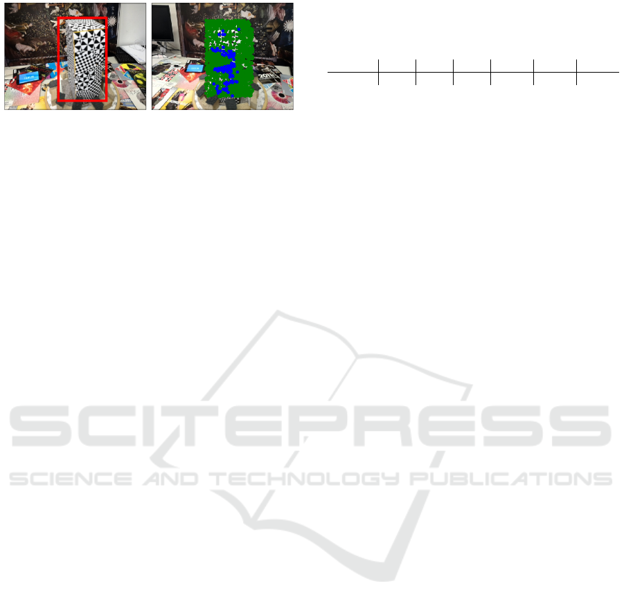
(a) (b)
Figure 5: Experimental setup: (a) Left-hand camera: red
box shows region of interest for our analysis. (b) Right-hand
camera: green points show keypoints extracted and blue
points show keypoints that have been 3D triangulated.
COLMAP. The 3D-reconstruction algorithm processed
all the pairs captured in the experiment. Fig. 5a shows
the object from the left-hand camera; the red bounding
box highlights the region of interest we have used for
our analysis of keypoints/3D points. Fig. 5b shows the
view from the right-hand camera with the keypoints,
highlighted in green, and the keypoints that have been
3D triangulated, shown in blue.
Latencies have been compared to those obtained us-
ing the Unity3D Relay (Unity3D Multiplayer Service,
2019). We also assessed the quality of 3D reconstruc-
tions over time by comparing the volumetric models of
the reference object under different network latencies
with respect to a ground truth, which was created by
reconstructing the reference object in 3D, frame-by-
frame with one degree of separation between frames,
for a total of 270 degrees. This created two sequences
of 270 aligned frames, one sequence for each cam-
era. By picking one frame from the first sequence and
then another frame from the second sequence captured
with a different pose, we could simulate different an-
gular velocities and different frame-capture rates. For
example, say we wanted to simulate the reference ob-
ject rotating at
50deg/s
, captured at
F = 10Hz
. This
corresponds to a 100ms interval between frames, cor-
responding to an object rotation of
5deg
. We can pick
frame
t
from the first sequence and frame
t + 5
from
the second sequence to simulate this condition. In
our experiments we simulated angular velocities be-
tween
50deg/s
and
100deg/s
with steps of
10deg/s
,
and modelled snapshots that were captured with a fre-
quency of
F = 10Hz
. We then modelled the latency
between the mobile and the Edge Relay by adding nor-
mally distributed delays, i.e.
N (µ, σ)
, where
µ
is the
mean and
σ
is the standard deviation that we measured
on our experimental WiFi network. In order to use real-
istic latency estimates, we recreated latency variation
conditions, ranging from
0
ms to
150
ms with a step
of
30
ms, by injecting delays into the network using
NetEm (NetEm, 2019). The mobiles were connected
via a WiFi 2.4GHz network. We used an off-the-shelf
Table 1: Round Trip Time between mobile and Edge Relay
measured on our WiFi network. ‘Set’ are the latencies set
with NetEm (NetEm, 2019), and ‘Meas’ are mean
±
standard
deviation calculated over 40 Round Trip time measurements.
Set (ms) 0 30 60 90 120 150
Meas (ms) 14 ± 11 50 ± 14 80 ± 31 108 ± 26 141 ±26 167 ±15
WiFi access point (Thomson TG587nV2). Due to in-
terference caused by neighbouring networks (a typical
scenario nowadays), we observed typical Round Trip
Times (RTT) shown in Tab. 1.
We used the data in Tab. 1 to quantify the triangu-
lation error between ground-truth 3D points and 3D
points triangulated under simulated delays. We cal-
culated the triangulation error using a grid composed
of 16
×
16-pixel cells defined within the bounding box
shown in Fig. 5a. Within each cell we select the key-
points that have been triangulated in 3D and calculated
the centre of mass of their 3D projection. We then cal-
culated the Euclidean distance between the 3D centres
of mass of the ground truth and the 3D centres of mass
of the points triangulated with different latencies.
End-to-End Delay Assessment.
We used two mo-
biles configured as the 3D reconstruction case to cap-
ture the time ticked by a stopwatch (up to the mil-
lisecond precision). We extracted the time information
from each frame pair of frames using OCR (Amazon
Textract, 2019) and computed their time difference.
We performed this experiment using the delay com-
pensation activated. The configurations tested are with
our Edge Relay operating locally (i.e. at the edge) and
in the cloud. For the latter we deployed our Edge Re-
lay on Amazon Web Services Cloud (AWS), and con-
nected the mobiles to the cloud through a high-quality
optical-fibre-based internet connection and though 4G,
to resemble a real capture scenario.
7.2 Experiments
Relay Latency.
We assessed synchronisation trigger
delays by measuring the latency between the host and
clients in the case of our Edge Relay and the Unity3D
Relay. We performed these measurements with a dedi-
cated feature integrated into the app that produces 250
RTT measurements. We then calculated the average
measured RTTs. Unity3D Relay is cloud based and
can be located anywhere around the globe, based on a
user’s location, the closest is usually queried (Unity3D
Network Manager, 2019). In the case of our Edge Re-
lay, we measured the host-client RTT and obtained an
average of
66 ± 37
ms. Then we measured the mobile-
Edge Relay RTT and obtained an average of
14±11
ms.
This means that
66 − 14 · 2 = 30
ms is consumed by
the network devices (e.g. router, access point) and by
the Edge Relay for processing. In the case of Unity3D
VISAPP 2020 - 15th International Conference on Computer Vision Theory and Applications
736
Relay (Unity3D Multiplayer Service, 2019), we mea-
sured the host-client RTT and obtained an average of
89 ± 12
ms. Then we measured the mobile-Unity3D
Relay RTT and obtained an average of
28 ± 13
ms.
This means that
89 − 28 · 2 = 33
ms is consumed by
network devices to reach the cloud and by the Unity3D
Relay for processing. The Unity3D Relay’s processing
time is comparable to that of our Edge Relay, but more
stable, as the standard deviation is smaller. We believe
that we can increase the efficiency of our Edge Relay
by re-implementing some core modules of MLAPI
(MLAPI, 2019) in C++. Furthermore, the RTT of
28
ms in the case of Unity3D Relay has been measured
inside a research centre with a high-quality optical-
fibre-based internet connection. To have an idea of
how other types of internet connections could affect
latency, we performed the same RTT measurement
towards Unity3D Relay but using a traditional 6Mbs
home broadband and a 4G connection, which turned
out to be 255 ± 66ms and 80 ± 7ms, respectively.
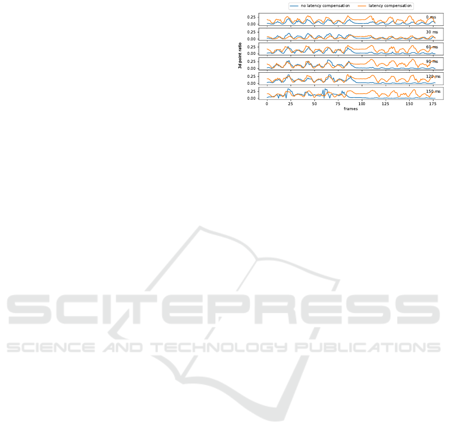
To illustrate the direct impact of synchronisation
delays on the 3D reconstruction, we designed another
experiment where our reference object is reconstructed
while rotating at an angular velocity of
ω = 80deg/s
.
This analysis is performed without using ground-truth
information. We performed various reconstructions of
the object by varying the latency between the mobiles.
In one experiment, the object performed two spins:
the first spin was 720 degrees counterclockwise, the
second spin was 720 degrees clockwise. We conducted
six experiments in total, where we injected 30ms of
communication delay into the WiFi network (using
NetEm (NetEm, 2019)) between the two mobiles for
each experiment. Note that if synchronisation trig-
gers are delivered with a delay, the object will appear
with a different pose in the two camera frames. This
affects the computation of the 3D points; matched
keypoints will correspond to different 3D locations,
and there will be parts of an object that might also
be occluded. In this first experiment, we could not
accurately measure the triangulation error through the
ground truth because we did not have direct access to
the angular state of the turntable during a spin. There-
fore, to make 3D reconstructions for each trigger and
for each experiment comparable, we quantified the
output as being the ratio between the number of 3D
points reconstructed and the keypoints visible within
the region of interest. We compared cases with latency
compensation disabled and then enabled. Fig. 6 shows
the variation of the 3D point ratio over time in these
two case. We refer to the left-hand mobile as A and
the right-hand as B. The first 100 frames correspond
to 720 degrees of counterclockwise spin. The eight
peaks correlate to a face of the box pointing towards
Figure 6: Instability of the 3D reconstruction when the la-
tency between two mobiles increases up to 150 ms. The 3D
point ratio is defined as the ratio between the number of 3D
points and the number of keypoints counted inside the region
of interest.
both mobiles. When latency compensation is disabled,
mobile A does not delay the frame capture by
ˆp
ms
(Sec. 5) when it sends a synchronisation trigger. As
the induced latency increases, mobile B receives its
trigger later and later. During this time, the object will
have rotated a few degrees in the same the direction
as mobile B, resulting in a more favourable viewpoint
for keypoint matching and 3D triangulation (i.e. it is
almost seeing an identical view as mobile A). Hence,
the 3D point ratio is seen to increase as the induced
latency increases when the rotation is counterclock-
wise. However, the computed 3D points will not be
calculated correctly and they will also have inaccurate
coordinates (we show quantitative evidence of this in
the next session). Vice-versa, when the rotation is
clockwise, mobile A is more likely to capture frames
of object regions that are occluded from mobile B’s
viewpoint as they will have already rotated out of view.
When our latency compensation algorithm is enabled,
3D reconstructions become symmetric in both spin-
ning directions, illustrating its effectiveness.
3D Reconstruction Analysis.
We quantify the recon-
struction accuracy using simulated latency (e.g. ground
truth). Fig. 7 and 8 show the 3D triangulation error in
cases of counterclockwise and clockwise spin, respec-
tively. From these graphs we see that the triangulation
error increases as simulated latency increases. This
occurs because after keypoints are matched across the
two image planes, and, after the keypoints are trian-
gulated in 3D (with an initially-guessed projection
matrix), the Bundle Adjustment algorithm in the SfM
pipeline tries to optimise the parameters of the projec-
tion matrix by minimising re-projection (3D to 2D)
error (Schonberger and Frahm, 2016). Hence, an er-
roneous object’s pose is captured, thus affecting the
estimation of the extrinsic and intrinsic parameters
(e.g. providing different focal-length estimates), and,
on the estimation of 3D points (i.e. highly likely to
be estimated somewhere in between the real 3D posi-
Multi-view Data Capture using Edge-synchronised Mobiles
737
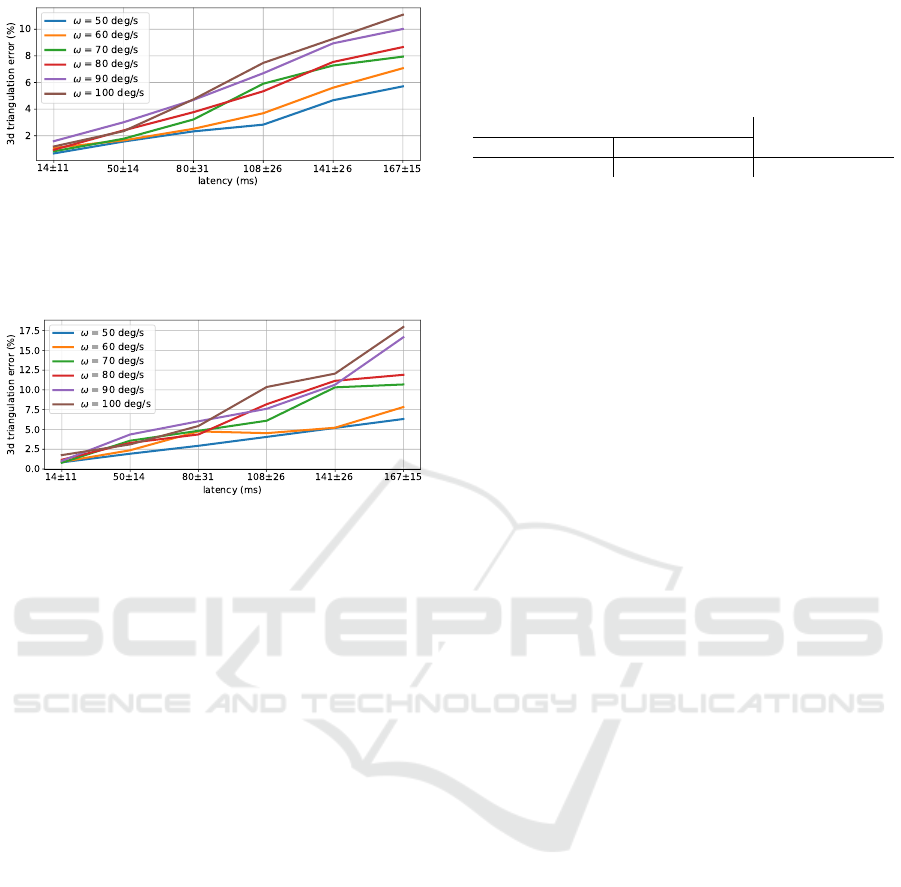
Figure 7: 3D triangulation error in the case of a
counterclockwise-spinning object. The error is computed
relative to the distance between the centre of mass of the two
cameras and the object, which is 40cm. The camera baseline
is fixed at 20cm.
Figure 8: 3D triangulation error in the case of a clockwise-
spinning object. The error is computed relative to the dis-
tance between the centre of mass of the two cameras and
the object, which is 40cm. The camera baseline is fixed at
20cm.
tion of the keypoints of the two frames). Error-rates
in the two cases differ due to the same phenomena
illustrated in Fig. 6. Because synchronisation triggers
are generated from the left-hand mobile, which takes
snapshots upon generation, the right-hand mobile only
takes snapshots when triggers are received. When the
object spins clockwise, the larger the delay the more
often the object appears with self-occluded parts in the
two cameras as it will have rotated more.
End-to-End Delay:
Tab. 2 shows the end-to-end de-
lay between mobiles, measured as the difference be-
tween the times captured from two mobiles through
OCR under different communication configurations
with the Edge Relay. As expected, the experiments
show evidence that when the Edge Relay is deployed
at the edge we can capture frames with the lowest la-
tency. When the Edge Relay is deployed in the cloud,
even through a highly reliable optical-fibre connection,
we can see that there is a worsening in the performance
due to the extra communication link to AWS.
Qualitative Analysis:
We qualitatively analyse the
performance of our approach by comparing the 3D
reconstruction over time of a moving person using the
standard Unity3D Relay (Unity3D Multiplayer Ser-
vice, 2019) and our Edge Relay. We used the AR
Anchor to estimate the scale of the point cloud in met-
ric units. Fig. 9 shows the dense point clouds in two
Table 2: End-to-end delay between mobiles, automatically
measured by capturing the time ticked by a stopwatch. Case
studies when Edge Relay was deployed in the cloud and
at the edge (i.e. locally). The connection to the cloud was
carried out through 4G and a high-quality optical fibre.
Cloud
Edge
4G Optical fibre
36.36 ± 25.46ms 25.40 ± 18.68ms 20.46 ± 18.95ms
instants of time where (1a,2a) are the outputs with
the Unity3D Relay and (1b,2b) with our Edge Re-
lay. We can see that when the object is still (Case
1) the results (i.e. density of triangulated 3D points)
using Unity3D Relay and Edge Relay are comparable.
Whereas, when the object moves (Case 2), synchro-
nisation is key to achieve accurate 3D triangulation,
and using the Unity3D Relay leads to sparser recon-
structions. We quantified the 3D triangulation accu-
racy by calculating the average reprojection error after
Bundle Adjustment. We measured
0.22 ± 0.04
pixels
using the Unity3D Relay and
0.20 ± 0.02
pixels us-
ing our Edge Relay. This result shows that we could
achieve a more accurate reconstruction using the Edge
Relay. During these experiments, we also monitored
the percentage of frames successfully received by the
Data Manager from all the mobiles. Given a snapshot
trigger, an instant of time that is captured only by a
subset of mobiles leads to a partial capture, as only
the frames of those mobiles that received the trigger
and performed the capture will be transmitted to the
Data Manager. We name these frames “partial frames”
and, ideally, we would like to achieve zero percent
of partial frames. The percentage of partial frames
we measured using Unity3D Relay was
41%
, whereas
with our Edge Relay it was
24%
. Frame loss is be-
cause snapshot triggers are transmitted through UDP,
that does not acknowledge if packets are received and
does not re-send packets in the case of failed recep-
tion (unlike with TCP). However UDP is necessary to
guarantee the timely delivery of packets. The video
of our qualitative analysis can be found at this link
https://youtu.be/znoJmovdCgs. The video illustrates
the effect of losing 3D points and frames with the
Unity3D Relay.
8 CONCLUSIONS
We proposed a system to move data-relaying from
the cloud to the edge, showing that this is key to
make frame capture synchronisation more reliable than
cloud-based solutions and to enable number-of-users
scalability. Our implementation consists of an Edge
Relay to handle snapshot triggers used for the captur-
ing of images for FVV production, and a Data Manager
VISAPP 2020 - 15th International Conference on Computer Vision Theory and Applications
738
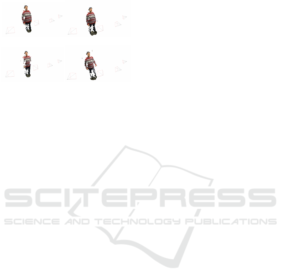
(1a) Unity3D Relay
(1b) Edge Relay
(2a) Unity3D Relay
(2b) Edge Relay
Figure 9: Examples of a moving person reconstructed using
(1a,2a) the Unity3D Relay (Unity3D Multiplayer Service,
2019) and (1b,2b) our Edge Relay. Case 1: When the object
is still we can see that results (i.e. density of triangulated 3D
points) using Unity3D Relay and Edge Relay are comparable.
Case 2: When the object moves, synchronisation is key to
achieve accurate 3D triangulation, and using the Unity3D
Relay leads to sparser reconstructions.
to receive capture frames via HTTP requests. Synchro-
nisation triggers are generated by a host, rather than
by a system timer, to enable a motion-based, adaptive
sampling-rate, fostering reduced data throughput. Al-
though the creation of high-quality FVVs was not the
scope of this work, we succeeded to show the benefit of
our decentralised data capturing system using a state-
of-the-art 3D reconstruction algorithm (i.e. COLMAP)
and by implementing the assessment of end-to-end
capture delays though OCR.
Future research directions include the integration
of a volumetric 4D reconstruction algorithm that can
be executed in real-time on the edge to providing tele-
presence functionality together with the integration
of temporal filtering of 3D reconstructed points to
provide more stable volumetric videos. We also aim
to improve reconstruction accuracy by postprocessing
ARCore’s pose estimates. By the end of this year we
will deploy our system on a 5G network and carry out
the first FVV production in uncontrolled environments
using off-the-shelf mobiles.
REFERENCES
Amazon Textract (Accessed: Dec 2019). https://aws.amazon.
com/textract/.
ARCore (Accessed: Dec 2019). https://developers.google.
com/ar.
ARCore Anchors (Accessed: Dec 2019). https://developers.
google.com/ar/develop/developer-guides/anchors.
Bastug, E., Bennis, M., Medard, M., and Debbah, M. (2017).
Toward Interconnected Virtual Reality: Opportunities,
Challenges, and Enablers. IEEE Communications Mag-
azine, 55(6):110–117.
Belshe, M., Peon, R., and Thomson, M. (2015). Hypertext
Transfer Protocol Version 2. RFC 7540.
Berners-Lee, T., Fielding, R., and Nielsen, H. (1996). Hy-
pertext Transfer Protocol Version 1. RFC 1945.
Cadena, C., Carlone, L., Carrillo, H., Latif, Y., Scaramuzza,
D., Neira, J., Reid, I., and Leonard, J. (2016). Past,
Present, and Future of Simultaneous Localization And
Mapping: Towards the Robust-Perception Age. IEEE
Trans. on Robotics, 32(6):1309–1332.
Chen, Y.-H., Balakrishnan, H., Ravindranath, L., and Bahl,
P. (2016). GLIMPSE: Continuous, Real-Time Object
Recognition on Mobile Devices. GetMobile: Mobile
Computing and Communications, 20(1):26–29.
Elbamby, M., Perfecto, C., Bennis, M., and Doppler, K.
(2018). Toward Low-Latency and Ultra-Reliable Vir-
tual Reality. IEEE Network, 32(2):78–84.
Garg, A., Yadav, A., Sikora, A., and Sairam, A. (2018). Wire-
less Precision Time Protocol. IEEE Communication
Letters, 22(4):812–815.
Guillemaut, J.-Y. and Hilton, A. (2011). Joint Multi-Layer
Segmentation and Reconstruction for Free-Viewpoint
Video Applications. International Journal on Com-
puter Vision, 93(1):73–100.
Hu, Y., Niu, D., and Li, Z. (2016). A Geometric Approach
to Server Selection for Interactive Video Streaming.
IEEE Trans. on Multimedia, 18(5):840–851.
Huang, C.-H., Boyer, E., Navab, N., and Ilic, S. (2014). Hu-
man Shape and Pose Tracking Using Keyframes. In
Proc. of IEEE Computer Vision and Pattern Recogni-
tion, Columbus, US.
Jiang, D. and Liu, G. (2017). An Overview of 5G Require-
ments. In Xiang, W., Zheng, K., and Shen, X., editors,
5G Mobile Communications. Springer.
Kim, H., Guillemaut, J.-Y., Takai, T., Sarim, M., and Hilton,
A. (2012). Outdoor Dynamic 3D Scene Reconstruc-
tion. IEEE Trans. on Circuits and Systems for Video
Technology, 22(11):1611–1622.
Knapitsch, A., Park, J., Zhou, Q.-Y., and Koltun, V. (2017).
Tanks and Temples: Benchmarking Large-Scale Scene
Reconstruction. ACM Transactions on Graphics,
36(4):1–13.
Latimer, R., Holloway, J., Veeraraghavan, A., and Sabharwal,
A. (2015). SocialSync: Sub-Frame Synchronization in
a Smartphone Camera Network. In Proc. of European
Conference on Computer Vision Workshops, Zurich,
CH.
MLAPI (Accessed: Dec 2019). https://midlevel.github.io/
MLAPI.
MLAPI Configuration (Accessed: Dec 2019). https://github.
com/MidLevel/MLAPI.Relay.
MLAPI Messaging System (Accessed: Dec 2019). https:
//mlapi.network/wiki/ways-to-syncronize/.
Mur-Artal, R., Montiel, J., and Tard
´
os, J. (2015). ORB-
SLAM: a versatile and accurate monocular SLAM sys-
tem. IEEE Trans. on Robotics, 31(5):1147–1163.
Mustafa, A. and Hilton, A. (2017). Semantically Coher-
ent Co-Segmentation and Reconstruction of Dynamic
Scenes. In Proc. of IEEE Computer Vision and Pattern
Recognition, Honolulu, US.
Multi-view Data Capture using Edge-synchronised Mobiles
739

NetEm (Accessed: Dec 2019). http://man7.org/linux/
man-pages/man8/tc-netem.8.html.
Park, J., Chou, P., and Hwang, J.-N. (2018). Volumetric
media streaming for augmented reality. In Proc. of
IEEE Global Communications Conference, Abu Dhabi,
United Arab Emirates.
Photon (Accessed: Dec 2019). https://www.photonengine.
com.
Poiesi, F., Locher, A., Chippendale, P., Nocerino, E., Re-
mondino, F., and Gool, L. V. (2017). Cloud-based
Collaborative 3D Reconstruction Using Smartphones.
In Proc. of European Conference on Visual Media Pro-
duction.
Qiao, X., Ren, P., Dustdar, S., Liu, L., Ma, H., and Chen,
J. (2019). Web AR: A Promising Future for Mobile
Augmented Reality–State of the Art, Challenges, and
Insights. Proceedings of the IEEE, 107(4):651–666.
QUIC (Accessed: Dec 2019). https://www.chromium.org/
quic.
Rematas, K., Kemelmacher-Shlizerman, I., Curless, B., and
Seitz, S. (2018). Soccer on your tabletop. In Proc. of
IEEE Computer Vision and Pattern Recognition, Salt
Lake City, US.
Resch, B., Lensch, H. P. A., Wang, O., Pollefeys, M., and
Sorkine-Hornung, A. (2015). Scalable structure from
motion for densely sampled videos. In Proc. of IEEE
Computer Vision and Pattern Recognition, Boston, US.
Richardt, C., Kim, H., Valgaerts, L., and Theobalt, C. (2016).
Dense Wide-Baseline Scene Flow From Two Handheld
Video Cameras. In Proc. of 3D Vision, Stanford, US.
Schonberger, J. and Frahm, J.-M. (2016). Structure-from-
motion revisited. In Proc. of IEEE Computer Vision
and Pattern Recognition, Las Vegas, USA.
Shi, W., Cao, J., Zhang, Q., Li, Y., and Xu, L. (2016). Edge
Computing: Vision and Challenges. IEEE Internet of
Things Journal, 5(3):637–646.
Shi, Z., Wang, H., Wei, W., Zheng, X., Zhao, M., and Zhao,
J. (2015). A novel individual location recommendation
system based on mobile augmented reality. In Proc.
of IEEE Identification, Information, and Knowledge in
the Internet of Things, Beijing, CN.
Slabaugh, G., Culbertson, B., Malzbender, T., and Schafer,
R. (2001). A Survey of Methods for Volumetric Scene
Reconstruction from Photographs. In International
Workshop on Volume Graphics, New York, US.
Soret, B., Mogensen, P., Pedersen, K., and Aguayo-Torres,
M. (2014). Fundamental tradeoffs among reliability,
latency and throughput in cellular networks. In Proc.
of IEEE Globecom Workshops, Austin, US.
Sukhmani, S., Sadeghi, M., Erol-Kantarci, M., and Saddik,
A. E. (2019). Edge Caching and Computing in 5G for
Mobile AR/VR and Tactile Internet. IEEE Multimedia,
26(1):21–30.
Unity3D HLAPI (Accessed: Dec 2019). https://docs.unity3d.
com/Manual/UNetUsingHLAPI.html.
Unity3D MatchMaking (Accessed: Dec 2019).
https://docs.unity3d.com/520/Documentation/
Manual/UNetMatchMaker.html.
Unity3D Multiplayer Service (Accessed: Dec 2019). https:
//unity3d.com/unity/features/multiplayer.
Unity3D Network Manager (Accessed: Dec 2019).
https://docs.unity3d.com/ScriptReference/
Networking.NetworkManager-matchHost.html.
Vo, M., Narasimhan, S., and Sheikh, Y. (2016). Spatiotem-
poral Bundle Adjustment for Dynamic 3D Reconstruc-
tion. In Proc. of IEEE Computer Vision and Pattern
Recognition, Las Vegas, US.
Wang, Y., Wang, J., and Chang, S.-F. (2015). CamSwarm:
Instantaneous Smartphone Camera Arrays for Collabo-
rative Photography. arXiv:1507.01148.
Wu, W., Yang, Z., Jin, D., and Nahrstedt, K. (2008). Im-
plementing a distributed tele-immersive system. In
Proc. of IEEE International Symposium on Multime-
dia, Berkeley, US.
Yahyavi, A. and Kemme, B. (2013). Peer-to-peer architec-
tures for massively multiplayer online games: A survey.
ACM Comput. Surv., 46(1):1–51.
Zhang, W., Han, B., and Hui, P. (2018). Jaguar: Low Latency
Mobile Augmented Reality with Flexible Tracking. In
Proc. of ACM International Conference on Multimedia,
Seoul, KR.
Zou, D. and Tan, P. (2013). COSLAM: Collaborative visual
slam in dynamic environments. IEEE Trans. on Pattern
Analysis and Machine Intelligence, 35(2):354–366.
VISAPP 2020 - 15th International Conference on Computer Vision Theory and Applications
740
