
A Generic Projectional Editor for EMF Models
Johannes Schr
¨
opfer, Thomas Buchmann and Bernhard Westfechtel
Chair of Applied Computer Science I, University of Bayreuth, Universit
¨
atsstrasse 30, 95440 Bayreuth, Germany
Keywords:
Model-driven Development, Projectional Editing, ALF, Java, Ecore, Syntax-directed Editor, Generic Frame-
work.
Abstract:
The Eclipse Modeling Framework (EMF) constitutes a popular ecosystem for model-driven development. In
the technological space of EMF, a wide variety of model-based tools have been developed, including tools
for transforming and editing models. Model editors may display models in different representations such
as diagrams, trees, or tables. Due to the increasing popularity of human-readable textual syntax, there is a
growing demand for textual model editors. In EMF, this demand is currently satisfied by syntax-based editors
which persist models as text files. In contrast, we propose a projectional editor that persists models natively
as EMF models; the textual representation constitutes a projection of the underlying EMF model. Projectional
editing does not only exclude syntactic errors; in addition, maintaining the underlying model persistently
facilitates tool integration. The projectional editor is generic; it may be instantiated for different modeling
languages by declarative definitions of their concrete syntax. So far, model editors for subsets of Java and
ALF (Action Language for Foundational UML) have been built to demonstrate the feasibility of the generic
approach.
1 INTRODUCTION
The Eclipse Modeling Framework (EMF) (Stein-
berg et al., 2009) constitutes a popular ecosystem
for model-driven development. In the technological
space of EMF, a wide variety of tools for model-
driven development have been implemented. EMF
has established itself as a de facto standard for data
models upon which many technologies and frame-
works are based, including server solutions, persis-
tence frameworks, UI frameworks, and support for
transformations
1
.
Model editors which provide tool support for cre-
ating, modifying, analyzing, and displaying mod-
els, constitute key components of environments for
model-driven development. Probably the first EMF-
based editor that has been provided is the tree editor
belonging to the EMF core. Since then, a number of
frameworks for building model editors have been de-
veloped for different model representations. For ex-
ample, frameworks such as GMF
2
and Sirius
3
(Ma-
diot and Paganelli, 2015) support the development of
1
https://www.eclipse.org/modeling/emf
2
https://www.eclipse.org/modeling/gmp/
3
https://www.eclipse.org/sirius/
diagram editors while EMF Parsley
4
(Bettini, 2014)
focuses on visualizations as trees, forms, or tables.
While diagrams have been frequently used for
representing models, human-readable textual syntax
has become more and more popular recently. The
term “human-readable” excludes textual representa-
tions such as XML that have been designed for data
exchange. Rather, human-readable syntax for mod-
els resembles the textual syntax of programming lan-
guages. The trend towards human-readable syntax
may be exemplified by recent work on the Action Lan-
guage for Foundational UML (ALF) (OMG, 2017a).
While the UML standard (OMG, 2017b) originally
defined only the abstract syntax of models and their
representation as diagrams, ALF provides a textual
language for both structural and behavioral model-
ing of a subset of UML (Foundational UML or fUML
(OMG, 2018)) that features foundational execution
semantics.
Textual editors may be divided roughly into two
categories. Syntax-based editors (cf. Figure 1) treat
the text as the primary artifact that is stored persis-
tently. A command issued by the user results in the
text being updated. Subsequently, the changes are
propagated to the model – i.e., to the abstract syntax
4
https://www.eclipse.org/emf-parsley/index.html
Schröpfer, J., Buchmann, T. and Westfechtel, B.
A Gener ic Projectional Editor for EMF Models.
DOI: 10.5220/0008971003810392
In Proceedings of the 8th International Conference on Model-Driven Engineering and Software Development (MODELSWARD 2020), pages 381-392
ISBN: 978-989-758-400-8; ISSN: 2184-4348
Copyright
c
2022 by SCITEPRESS – Science and Technology Publications, Lda. All rights reserved
381

Syntax-Based
Editor
Modeler
(1) Issues Command
TextModel
(3) Propagates Changes
(4) Updates Model (2) Updates Tex t
(Transient) (Persistent)
Figure 1: Syntax-based editing.
tree that is represented by the plain text. The model
is maintained only transiently, during an editing ses-
sion, and is used primarily for incremental syntactic
and semantic analysis.
In the technological space of EMF, among several
tools for building syntax-based editors, e.g., EMF-
Text
5
(Heidenreich et al., 2011) for textual languages
that can be easily extended and integrated with other
languages, the framework Xtext
6
(Bettini, 2016) is
the most prominent one. The editors are generated
from a grammar definition that refers to an underly-
ing metamodel. Grammar rules in Xtext are based
on the Extended Backus-Naur Form (EBNF) (Yue,
2014). Either the starting point is the grammar from
which the metamodel is generated (concrete syntax
first) or the grammar is specified for an existing meta-
model (abstract syntax first) which has been built us-
ing any tool in the EMF context (e.g., the Ecore tree
editor). The generated editor artifacts can be aug-
mented with Xtend
7
classes describing the custom
scoping rules, validation constraints, hovering infor-
mation, highlighting, etc. The (customized) editor
plug-ins for the specific language may be used by ar-
bitrary EMF-based projects.
Syntax-based editors are flexible since they allow
the modeler to issue arbitrary text-based commands.
For the same reason, they are easy to learn (usually,
the modeler is familiar with the operation of text edi-
tors). On the other hand, they suffer from the follow-
ing shortcomings:
• There is a high risk of syntactic errors since the
modeler may type arbitrary text. This may be
problematic for beginners who are not familiar
with the respective modeling language.
• Tool integration may be hampered by storing
models as text files. For example, models may
5
https://marketplace.eclipse.org/content/emftext
6
https://www.eclipse.org/Xtext/
7
a Java dialect, see https://www.eclipse.org/xtend/
Projectional
Editor
Modeler
(1) Issues Command
TextModel
(3) Propagates Changes
(2) Updates Model (4) Updates Tex t
(Persistent) (Transient)
Figure 2: Projectional editing.
be related by inter-model links, e.g., traceability
links connecting models at different levels of ab-
straction or links between features and domain
model elements in software product lines. Since
text files do not provide for reliable identifiers of
model elements, inter-model links may be easily
corrupted.
Projectional editors (cf. Figure 2) invert the
syntax-based approach to model editing. Rather than
the text (concrete syntax), the model (abstract syn-
tax) is persisted. In the context of product line engi-
neering, a great importance is attached to projectional
editors, e.g., the PEoPL approach (Behringer et al.,
2017) combines different representations. Commands
issued by the modeler affect the model rather than the
text. After the model has been updated, the changes
are propagated to the text which is updated accord-
ingly in turn. For experienced users, projectional
editors may feel less natural and comfortable than
syntax-based editors (V
¨
olter et al., 2014). On the
other hand, projectional editors solve the problems
mentioned above:
• A projectional editor guarantees syntactic cor-
rectness by offering only commands that per-
form correctness-preserving in-place model trans-
formations. For example, a command for insert-
ing some syntactic unit is allowed only at loca-
tions where this unit is legal and ensures syntactic
correctness of the inserted syntactic unit.
• A projectional editor facilitates tool integration by
providing reliable means for identifying model el-
ements. While line numbers in text files are sub-
ject to change, elements may be assigned uni-
versally unique identifiers (UUIDs) that are im-
mutable.
This paper fills a gap in the EMF tool landscape by
providing a generic projectional editor for EMF mod-
els that is distinguished by the following key proper-
ties:
MODELSWARD 2020 - 8th International Conference on Model-Driven Engineering and Software Development
382

• The projectional editor stores the abstract syntax
of some model as an ordinary EMF model, en-
abling integration with any EMF-based tool for
model transformations, code generation, etc.
• The projectional editor is generic inasmuch as an
EMF model may be instantiated from an arbi-
trary metamodel (defining the abstract syntax of
some modeling language) that provides univer-
sally unique identifiers for objects.
• So far, the projectional editor supports textual rep-
resentations. However, its underlying design is
extensible such that support for other representa-
tions (e.g., diagrams) may be added in the future.
• Deviating from Figure 2, representations are per-
sisted, as well – again as EMF models. This
approach allows to persist representation-specific
information such as layout of text or diagrams
(which may be improved manually by the mod-
eler).
• The editor may be adapted to a specific modeling
language by providing a declarative syntax defi-
nition which is used to map abstract to concrete
syntax. No programming is required to this end.
Projectional editors are not a new invention.
Rather, they were devised several decades ago
as components of integrated programming environ-
ments; see (Medina-Mora and Feiler, 1981; Haber-
mann and Notkin, 1986; Bahlke and Snelting, 1986;
Ballance et al., 1992; Klint, 1993) for some early ap-
proaches. In this context, they were called syntax-
directed editors. Currently, the Meta Programming
System (MPS)
8
by JetBrains (Campagne, 2015) con-
stitutes a contemporary framework for developing
projectional editors – not just for text but also for
other representations such as two-dimensional math
notations, tables, or forms. MPS also provides sup-
port for language modularization as well as compo-
sition (Voelter, 2011). In (Ratiu et al., 2017), expe-
riences with teaching MPS in industry are outlined.
Recent research deals with support for incremental
model transformations (Voelter et al., 2019).
While this framework is powerful, it comes with
a proprietary data model. Instead of an open ecosys-
tem, MPS provides a closed language workbench that
requires its users to commit to the MPS data model
and tool set. For defining languages, MPS uses hier-
archies of concepts and their implementations: While
in the world of EMF, the abstract syntax of a language
may be defined by metamodels using arbitrary editors
(e.g., the standard Ecore tree editor but also graphi-
cal editors), in MPS one concept is defined textually
8
https://www.jetbrains.com/mps/
for each type in a separate file – similar to defining
Java classes. Furthermore, instead of specifying the
concrete syntax similar to a grammar, each concept
provides an additional text file to describe the nota-
tion of the respective element. For defining custom
scoping, validation, building a type system, etc. also
a special textual notation is used instead of providing
artifacts in a common general-purpose language.
The rest of this paper is structured as follows: Sec-
tion 2 provides an overview of our approach to pro-
jectional editing. Section 3 explains the functionality
and the user interface of the projectional editor by out-
lining an exemplarily editing process within a sample
ALF editor. Section 4 describes its underlying soft-
ware architecture. Section 5 introduces the language
that is used for context-free syntax definitions while
Section 6 illustrates implementing static semantics by
means of respective extension points. Finally, Sec-
tion 7 concludes by an outlook on current and future
work.
2 APPROACH
As stated above, projectional (syntax-directed) edit-
ing differs significantly from syntax-based editing
since the abstract syntax rather than the concrete syn-
tax serves as the primary artifact.
In the current implementation of our framework,
we assume that the abstract syntax, i.e., the meta-
model of the language to be developed, has been
specified yet in terms of an Ecore model. In order
to be used for arbitrary Ecore models, our frame-
work has to be as generic as possible. Figure 3
depicts an overview of our basic editing approach
within the EMF context. Two different kinds of users
are distinguished: While the DSL Developer defines
the context-free syntax of the language as well as
the static semantics including scoping rules and type
checking, the Modeler uses the configured editor for
Context: Eclipse Modeling Framework
Ecore
Syntax
Definition
Projectional
Editor
Editor
Providers
Abstract
Syntax Tree
Representation
Model
DSL
Developer
Modeler
interprets
uses
customizes
specifies
issues
command
modifies
semantics
modifies
layout
propagates
changes
based on
based on
based on
Figure 3: The editing approach of the framework.
A Generic Projectional Editor for EMF Models
383
creating and modifying models.
First, the DSL developer is considered. This actor
defines the concrete syntax (cf. Section 5) as well as
static semantics (cf. Section 6). From the metamodel
describing the abstract syntax of the language, an in-
complete editor plug-in is generated. It contains one
(initially empty) text file where the DSL developer
defines the context-free syntax; to this end, an intu-
itive textual language is used that allows for declara-
tive syntax definitions. The projectional editor works
with generic commands that are executed by inter-
preting the persisted syntax definition. In order to
provide further customizations, in particular static se-
mantics, code stubs are generated in which the DSL
developer can override the default behavior, e.g., by
specifying custom scoping rules and validation con-
straints. Our primary design decision was to generate
only the most essential parts (i.e., a minimum number
of lines of code) and to provide the main functional-
ity, especially the edit commands, in global modules.
As a result, the DSL developer is not bothered with a
large number of generated code lines including tech-
nical details concerning the editing commands and the
possible extension points which allow for customiz-
ing the default behavior become clearly visible.
After the context-free syntax and the static seman-
tics have been specified completely, the modeler uses
the editor (cf. Section 3) in order to alter a persisted,
underlying model while the editor visualizes its repre-
sentation that is also persisted such that view-specific
information can be stored. After the abstract syntax
tree has been modified by means of appropriate com-
mands, the changes are propagated to the represen-
tation model. Apart from commands modifying the
abstract syntax tree, several commands are provided
in order to customize the representation (e.g., insert-
ing layout elements) without having any impact on the
abstract syntax tree.
The editing process in projectional editors is based
upon commands which alter the underlying model.
Consequently, free text editing is no longer possible
even for textual representations (editing commands
have to be used instead). However, we strive for an
editing experience which comes close to free text edit-
ing. While our primary focus is a textual representa-
tion of the model, we do not want to limit ourselves to
plain text. Instead the framework is designed in a way
which allows for adding other model representations
(diagrams, tables, etc.) in a later stage.
3 PROJECTIONAL EDITING
This section outlines the functionality of our frame-
work from the modeler’s point of view. After a gen-
eral description, a sample scenario using the frame-
work is demonstrated; the example considers the tex-
tual modeling language ALF for which a projectional
editor is developed.
3.1 General Aspects
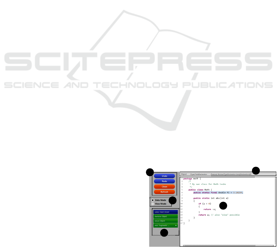
Figure 4 depicts a screenshot of the user interface of
the editor. The major part of the editor constitutes the
main pane (cf. part 1) that presents the representa-
tion of an underlying abstract syntax tree. The editor
provides two modes from which the user may choose
(cf. part 2): the data mode and the view mode. De-
pending on the chosen mode, adequate operations are
provided by means of buttons (cf. part 3) when the
user performs a selection within the main pane. For a
representation element that is selected within the data
mode, summarizing information about the underlying
model element is provided (cf. part 4). Additionally,
some independent operations – e.g., Undo and Redo
– can be invoked (cf. part 5).
The data mode supports commands in the form of
button events (cf. Figure 4, part 3) for editing the
abstract syntax tree. After modifying the underly-
ing model, the changes are propagated to the repre-
sentation model and become visible at the user inter-
face. The list of available commands depends on the
selection performed by the user; besides single cells
representing values, also representation elements of
objects or structural features of them – which con-
sist of several cells that are logically connected – can
be selected. Editing commands comprise setting val-
ues and links, adding and removing objects, as well
as adding and removing optional representation ele-
ments based on (boolean) structural features (e.g., the
keyword abstract is visible if and only if the respec-
5
2
3
1
4
Figure 4: The editor user interface and its components.
MODELSWARD 2020 - 8th International Conference on Model-Driven Engineering and Software Development
384
1
2
3
45
6
7
8
9
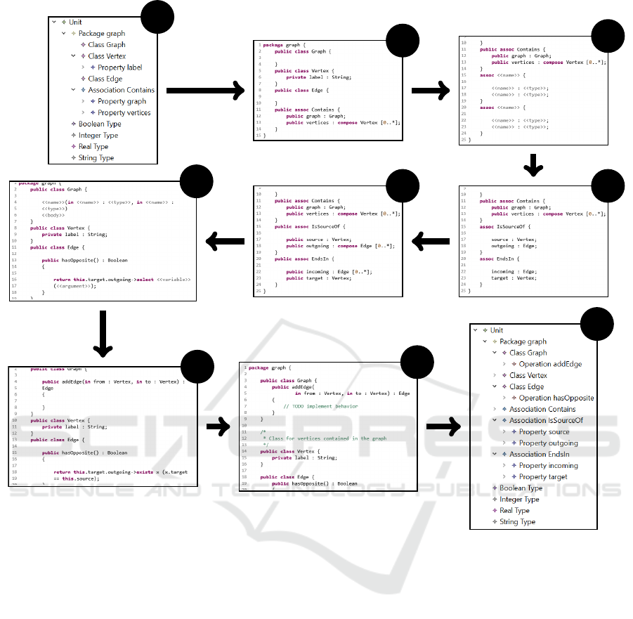
Figure 5: Exemplary editing workflow for an ALF model.
tive attribute isAbstract is set to true). Future work
will deal with extensions and additional keyboard ac-
tions in order to provide a more comfortable look-
and-feel when using the editor. In addition, the view
mode supports commands which affect the represen-
tation only and do not affect the underlying abstract
syntax tree. For instance, in order to modify the lay-
out, space characters, tabulators, and line breaks can
be inserted using keyboard events.
While the commands described above only con-
sider an editing process that is performed completely
within the editor, an independent evolution of the ab-
stract syntax tree outside the editor is also captured.
This facilitates a pretty flexible integration with other
frameworks, e.g., the abstract syntax tree can be the
target of a model transformation. For an incremen-
tal synchronization, a Refresh button is provided (cf.
Figure 4, part 5). This process is also used for generat-
ing an initial representation model for a given abstract
syntax tree; this action can be executed by means of a
right-click operation on the model file containing the
abstract syntax tree.
3.2 Example Scenario
We demonstrate the functionality of our framework
for the textual modeling language ALF that allows for
specifying models comprising structural as well as be-
havioral elements. An example workflow is shown in
Figure 5. The general case is considered that the mod-
eler starts with an initial abstract syntax tree which
is modified and extended using the projectional edi-
tor within several subsequent editing steps. The ini-
tial abstract syntax tree (cf. step 1; the model is
shown within the generic EMF model tree editor) has
a package containing several classes and one associ-
ation describing the structure of graphs. This model
could also constitute the result of a model transforma-
A Generic Projectional Editor for EMF Models
385
tion with a UML model (class diagram) as its source
model. Invoking the initial synchronization command
results in creating the representation model for the
given abstract syntax tree (cf. step 2; the model is
displayed now in the projectional editor).
Next, two additional associations containing prop-
erties as their association ends are added. Neither val-
ues nor cross links have been specified yet (cf. step 3,
gray placeholders represent representation elements
for missing values, links, or child objects). There-
upon, the names of the association and its properties
as well as the missing types are specified (cf. step 4).
Currently, the objects are still not complete. After in-
voking commands for setting optional elements (e.g.,
visibilities and multiplicities), the missing informa-
tion is added (cf. step 5).
During the next steps, operations are added. First,
the objects are created. The operation hasOpposite()
is also augmented with several values and child ob-
jects (name, return type, parameters, and body); for
its implementation, a SequenceExpansionExpression
instance is used that applies a functional operation to a
collection (cf. step 6). Aside from the behavior of the
operation addEdge(. . . ), the objects are defined com-
pletely (cf. step 7).
Before finishing the editing process, representa-
tion commands are used in order to customize the lay-
out by means of additional line breaks, whitespaces,
etc. (cf. step 8). The commands modify the represen-
tation model while the underlying abstract syntax tree
is not affected. In addition, some comments are in-
serted. Finally, the changes performed using the pro-
jectional editor are saved which stores the underlying
abstract syntax tree as displayed in the EMF tree edi-
tor (cf. step 9).
4 ARCHITECTURE
This section describes the architecture of the frame-
work. After a brief overview of involved (internal
and external) components and their dependencies, the
foundations of the representation metamodel are pre-
sented. Finally, details about the presentation within
the editor are given.
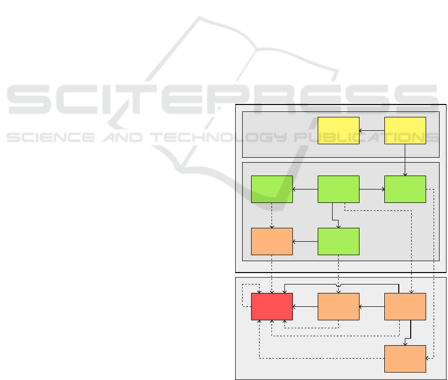
4.1 Overview
Figure 6 depicts an overview of the models in-
volved in a general editing workflow and the rela-
tionships between them. Currently, the framework
works with exactly one model that contains the ab-
stract syntax tree (AST Model). The metamodel of
the AST model (AST Metamodel) may be an arbi-
trary Ecore model; besides the prerequisite that it
constitutes an instance of Ecore using universally
unique identifiers (UUIDs) for objects, there are no
further assumptions or restrictions. For a specific
metamodel, its concrete syntax is stored within the
Syntax Definition Model (cf. Section 5). The editor
(Editor GUI) shows a representation of the AST model
(Representation Model, cf. Section 4.2). At runtime,
a data structure (Representation/Presentation Map-
ping) stores the traces connecting graphical elements
of the user interface with persisted representation ele-
ments (cf. Section 4.3).
Elements from the abstract syntax tree, the repre-
sentation, and the syntax definition are connected by
means of a Mapping Model. It persists the traces be-
tween the involved models storing different informa-
tion and therefore serves as the technical background
enabling the functionality of the editor and its com-
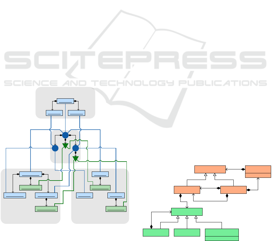
mands. The structure of a model system contain-
ing mapping model, abstract syntax tree, representa-
tion model, and syntax definition model is depicted in
Figure 7. Two kinds of mappings are distinguished:
the object mappings and the feature mappings (where
features refer to structural features). For each object
within the abstract syntax tree (an EObject instance),
Editor
GUI
Representation/
Presentation
Mapping
Representation
Model
Mapping
Model
AST
Model
Syntax
Definition
Model
AST
Metamodel
Ecore
Syntax
Definition
Metamodel
Mapping
Metamodel
Representation
Metamodel
runtime artifacts
persisted models
specific externals
generic (fixed) internals
Figure 6: Overview of the underlying architecture. Solid
arrows visualize dependencies in terms of references while
dashed arrows indicate instanceOf-relationships.
MODELSWARD 2020 - 8th International Conference on Model-Driven Engineering and Software Development
386
the mapping model contains an object mapping. Each
object mapping provides traces between the AST el-
ement, the respective representation element, and the
underlying pattern within the syntax definition. Fur-
thermore, elements within the syntax definitions that
refer to structural features of the considered meta-
model (e.g., the feature reference for the list of param-
eters within the pattern for operations) of the abstract
syntax tree are connected with respective representa-
tion elements by means of feature mappings.
The mapping model contains its elements within
a containment hierarchy corresponding to the objects
within the abstract syntax tree as well as their repre-
sentation objects. If an AST object o
1
is contained in
the object o
2
, the representation element r
1
(that rep-
resents o
1
) is contained in r
2
(that represents o
2
) and
the object mapping m
1
(that maps o
1
to r
1
) is con-
tained in m
2
(that maps o
2
to r
2
). Feature mappings
are contained in the object mappings that refer to the
respective objects within the abstract syntax tree.
4.2 Representation Concepts
The representation metamodel allows for instances
that represent arbitrary abstract syntax trees. Cur-
rently, a purely textual representation is supported.
The metamodel is designed in a way that allows for
extensions with additional forms of representation,
e.g., graphical representation. The concepts refer-
: EObject
: EObject : EObject
: ObjectRepr
: ObjectRepr : ObjectRepr
: FeatureRepr
: FeatureRepr
: Pattern
: Pattern : Pattern
: FeatureRef
: FeatureRef
Representation Syntax Definition
Abstract Syntax Tree
Figure 7: The structure of a mapping model containing
mappings for objects (denoted by circles) as well as map-
pings for features (denoted by triangles). Diamond arrows
visualize (direct or transitive) containment relations.
ring to textual representation are inspired by program-
ming languages as Java. The model elements possess
block or line structures: While a for-loop or a switch-
statement in Java constitute block patterns containing
head lines and bodies, assignments or arithmetic ex-
pressions are line patterns.
The simplified representation metamodel is shown
in Figure 8. A block always contains a body and may
have an optional head line and an optional tail line. A
body has an indentation number and contains a col-
lection of body elements. A body element is either a
block or a line. A line instance constitutes the connec-
tion between block and line structure and describes a
logical line that may comprise several physical lines.
To this end, besides the cells storing the text visible to
the user, a logical line contains line breaks; line breaks
can be generated in order to ensure width bounds of
the surrounding pane. Syntactically linked line ele-
ments can be grouped to fragments.
The representation models contain logical ele-
ments for object representations and feature repre-
sentations. An object representation – which is con-
nected to an AST object and a syntax definition ele-
ment via a proper element within the mapping model
– is either a block (block structure) or a fragment
(line structure); a feature representation – that is con-
nected to a corresponding syntax definition element
via a mapping element – is either a body or a frag-
ment. The design principle of logical lines instead
of modeling a container object for each physical line
facilitates modifications of the representation model
with only a small effort when physical line breaks are
added, removed, or moved, e.g., after cells and frag-
ments have been changed.
4.3 From Representation to
Presentation
The editor user interface visualizes the representation
model using proper JavaFX elements. The Java-based
BodyElement
Line Block
Body
LineElement
Fragment
Cell LineBreak
generated : Boolean
indent : Integer
0..1
tail
0..1
head
*
elements
*
elements
1
body
*
elements
Figure 8: Kernel of the representation metamodel.
A Generic Projectional Editor for EMF Models
387
framework JavaFX
9
comes along with a GUI library
for creating desktop and rich web applications. It in-
cludes special components to support an integration
with SWT (Standard Widget Toolkit)
10
, the graphical
toolkit used for the Eclipse IDE. When the editor is
saved, all model files involved in the model system
– representation model, mapping model, and the ab-
stract syntax tree – are saved.
The major editor part is the main pane. For per-
formance reasons, only a subset of all representation
elements are mapped to corresponding GUI elements.
Fragments are not mapped to presentation elements at
all. Cells contained in the representation model are
mapped to JavaFX labels. Blocks and their bodies are
mapped to rectangles.
When a GUI element is created for a representa-
tion element, the trace that connects the runtime ele-
ment and the persisted representation object is stored
within a mapping structure. Using this data structure,
the presentation can be modified incrementally when
the representation model is changed.
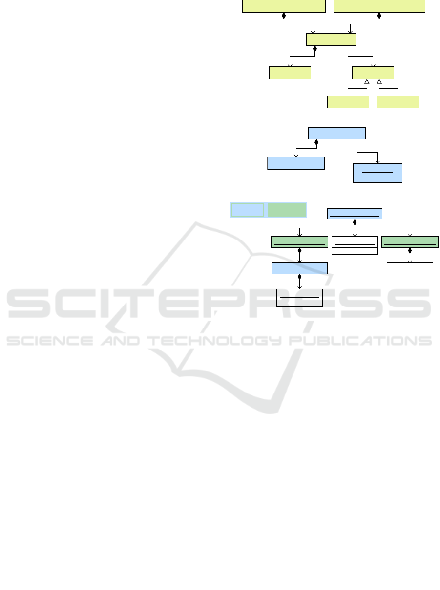
4.4 Sample Model System
In this section, the architecture concepts depicted
above are applied to an exemplary cutout of an ALF
model. Figure 9 shows the relevant part of the ALF
metamodel as well as an example abstract syntax tree
and its representation model. The cutout of the meta-
model (cf. Figure 9a) refers to feature access expres-
sions, i.e., references to ALF properties or calls of
ALF operations. In this case, a reference of an ALF
property is considered (cf. Figure 9b); the FeatureAc-
cess object contains a ThisExpression and has an out-
going cross link to a Property instance. The repre-
sentation model (cf. Figure 9c) consists of line ele-
ments only; it contains three cells which are grouped
by means of fragments. For both references expres-
sion and feature, corresponding FeatureFragment ob-
jects are present. For the FeatureAccess and the This-
Expression objects within the abstract syntax tree, the
representation model contains corresponding Object-
Fragment objects.
The abstract syntax tree, the representation ele-
ments, and the elements within the syntax definition
are connected by mappings. An object mapping con-
nects an object in the abstract syntax tree with the
corresponding pattern in the syntax definition as well
as the representation element (in this case an Object-
Fragment object) in the representation model. Feature
references within the syntax definition are connected
with appropriate representation elements (in this case
9
https://www.eclipse.org/efxclipse/index.html
10
https://www.eclipse.org/swt/
FeatureAccess
PropertyAccessExpression FeatureInvocationExpression
Expression
Feature
Property Operation
expression
1
feature
1
access
1
target
1
(a) Cutout of the ALF metamodel.
: FeatureAccess
: ThisExpression
: Property
expression
feature
name = label
(b) The abstract syntax tree as an instance.
this.label
: ObjectFragment
: FeatureFragment : FeatureFragment: ConstantCell
: ConstantCell
: ObjectFragment : CrossLinkCell
elements elements elements
elements elements
elements
constant = .
constant = this
value = label
(c) The corresponding representation model in concrete and
in abstract syntax.
Figure 9: The model system for an exemplary ALF model.
FeatureFragment objects) by feature mappings. The
object hierarchy of the abstract syntax tree is retained;
the object mapping for the ThisExpression is con-
tained in the one for the FeatureAccess instance. The
feature mappings for the references are child elements
of the object mapping for the FeatureAccess object.
The user interface of the projectional editor shows
labels for the cells contained in the representation
model. When the modeler, for instance, changes the
referenced property, i.e., the value label is altered, first
the cross link within the abstract syntax tree is mod-
ified, afterwards the cross link cell in the representa-
tion model is adapted, and finally the corresponding
label of the user interface is changed.
5 CONTEXT-FREE SYNTAX
DEFINITIONS
The context-free mapping from the abstract syntax to
the concrete syntax is performed by means of projec-
tion rules. This section describes the structure and
MODELSWARD 2020 - 8th International Conference on Model-Driven Engineering and Software Development
388

feasibilities of the textual metalanguage for the pro-
jection rules as well as the editor for defining them.
The language is exemplarily depicted by syntax defi-
nitions of some ALF elements that are visible in Sec-
tion 3.2, Figure 5 which employ the most important
language features.
5.1 The Syntax Definition Language
Analogously to the representation concepts (cf. Sec-
tion 4.2), the structure comprises blocks and lines.
The layout of the projection rules does not have any
semantical background. Rather, keywords are used
to describe blocks, bodies, lines, and line elements.
For each non-abstract metaclass, several patterns can
be defined. Each pattern is surrounded by the key-
words def and enddef and is either a block pattern –
containing an optional head directive, a body with a
collection of body elements, and an optional tail di-
rective – or a line pattern – containing a collection of
line elements. Listing 1 depicts a projection rule that
defines the syntax of ALF classes (Class objects) by
means of a block pattern. It contains a head directive
(cf. lines 2 ff.) as well as a body (cf. lines 7 ff.).
1 def C la ss
2 head [ftr v is ib il i t y Vi si bi l i t y endftr]
3 [ ’ ab st r a c t ’ ? i sA b s t ra ct ]
4 ’ c l as s ’ ftr n am e String endftr
5 [ftr s p e c ia li z at io n seq cross Cl a ss
6 delim ’ , ’ endseq endftr]
7 body ind 4 ftr o w n e dM em be r delim ’{ ’ ’} ’
8 seq
9 M em be r
10 endseq
11 enddef
Listing 1: A projection rule for defining ALF classes.
Patterns contain feature references, i.e., elements
referring to structural features. A feature reference is
either a line element containing further line elements
or a body containing body elements. All structural
features of the class or of a supertype can be addressed
by feature references contained in the patterns with
the restriction that in each pattern, each structural fea-
ture is referenced at most once. The head directive of
the pattern shown in Listing 1 contains aside from the
keyword class feature references for the attributes vis-
ibility (cf. line 2) and name (cf. line 4) as well as the
cross reference specialization (cf. lines 5 f.). All fea-
ture references in the head directive are line elements,
starting with the keyword ftr followed by the name of
the feature and ending with the keyword endftr with
the containing line elements in between.
The feature references for the attributes visibility
and name contain access elements for their values.
While for the string value of the attribute name, the
keyword String is provided (cf. line 4), the feature
reference for the attribute visibility contains a link to
the enumeration definition Visibility (cf. line 2, con-
tains a link to Listing 3). Cross links (e.g., the links
for the reference specialization) are denoted by the
keyword cross followed by the expected type (in this
case the metaclass Class, cf. line 5). Sequences of
elements (e.g., sequences of referenced superclasses,
cf. lines 5 f.) are represented by the surrounding key-
words seq and endseq with an optional separator ele-
ment between the elements (keyword delim). For op-
tional fragments, square brackets are used – inspired
by EBNF. Since neither a visibility value nor super-
classes are mandatory elements within in the con-
crete syntax, the fragments are optional. Additionally,
the keyword abstract is optional; it is bound to the
boolean attribute isAbstract, i.e., the keyword is set if
and only if the boolean value is set to true, denoted by
the quotation mark followed by the respective boolean
attribute (cf. line 3).
The body (cf. lines 7 ff.) constitutes another fea-
ture reference that refers to the containment reference
ownedMember (keyword ftr) and possesses a specified
indentation (keyword ind) as well as delimiters (key-
word delim); while for sequences the keyword delim
is followed by the separator (e.g., a comma for sep-
arating ALF parameters), for bodies it introduces the
surrounding characters (e.g., curly brackets surround-
ing class bodies). The body of an ALF Class contains
a collection of members. For containment references,
the feature reference contains access to a pattern or an
alias (cf. line 9, contains a link to the alias definition
shown in Listing 2).
1 alias M em be r
2 (
3 line P r o p e r t y endline |
4 Op er a t i o n
5 )
6 endalias
Listing 2: An alias for ALF properties and operations.
Members of ALF classes can be Property and Op-
eration objects. In order to bundle the metaclasses,
an alias Member can be defined that is shown in List-
ing 2. In contrast to patterns, aliases are named defini-
tions for parts of patterns – as a kind of variables used
several times – which do not refer to metaclasses.
Disjunctions are denoted by surrounding parenthe-
ses and a delimiting pipe symbol – also inspired by
EBNF. While operations have a block structure, a
A Generic Projectional Editor for EMF Models
389

property has a line structure. Therefore, properties
constitute line elements and not block elements; by
means of surrounding line and endline keywords (cf.
line 3), line elements can be converted into a block
element in order to be compatible to the structure of
the respective context.
While for primitive attributes, the keywords
String, Integer, etc. are provided, for enumerations,
special definitions are specified by using the key-
words enum and endenum. Listing 3 depicts the enu-
meration rule for visibilities (referenced by Visibility
in Listing 1). Enumeration literals are identified by
their literal strings. After all the visible literals are
defined (cf. line 2), an optional blank value can be
added (cf. line 3); blank values are default values for
which no literal is set within the concrete syntax (in
this case, for package visibility, no keyword is pro-
vided by ALF).
1 enum Vis i b i li ty
2 ’ p ub l ic ’ ’ pr iv at e ’ ’ p ro te ct ed ’
3 blank ’ p ac ka ge ’ endenum
Listing 3: An enumeration for ALF visibilities.
The editor commands for mapping the abstract
syntax tree elements to elements of the representation
models interpret the resulting syntax definition model.
Block and line structures of the projection rules are
mapped to block and line structures of the represen-
tation model. Line elements within the syntax defini-
tion (e.g., keywords and value access elements) are in-
serted in representation lines with separating whites-
paces, by default. In order to prevent a whitespace
at the specified position (e.g., for ALF multiplici-
ties, the square brackets surround the bounds without
any whitespaces), the keyword nospace is provided.
In the representation model, bodies are contained in
blocks with an indentation that is specified by the cor-
responding body in the syntax definition. In order to
add additional empty lines within a body, the keyword
extraline can be used.
5.2 The Syntax Definition Editor
For specifying the context-free syntax, a textual edi-
tor is provided. So far, for our framework we assume
that the projection rules are fixed and do not change
after they have been defined by the DSL developer.
Currently, the editor is realized with Xtext. When
the rules are specified completely, a persistent model
is built from the text file that is used for references
within the architecture of the framework.
Besides comfortable tool support as highlight-
ing, hovering, and code completion, the editor comes
along with a validator that checks for compliance with
several constraints. One significant constraint is that
referenced patterns for child objects are compatible to
the context. The type of a referenced pattern within a
feature reference must conform to the type of the fea-
ture reference. Apart from type compatibility, also
structural compatibility must be ensured; an object
with block structure cannot be contained in a line,
for instance. Furthermore, for each metaclass, all pat-
terns must be unique with respect to the names.
For the future, we plan a bootstrapping process
that provides for using our editor for the syntax defini-
tion language in order to avoid dependencies to third-
party frameworks.
6 IMPLEMENTING STATIC
SEMANTICS
This section describes the extension points to our
framework for defining static semantics of the lan-
guages that are implemented by the DSL developers.
When a plug-in is generated for a language, empty
high-level code stubs are generated which can be im-
plemented by the DSL developer. We strive for a very
user-friendly environment which makes customizing
the providers as intuitive as possible. Future work
comprises support for custom validation, code high-
lighting, hovering, etc.
Listing 4 shows a cutout of the scope provider for
ALF as the example language (cf. Section 3.2, Fig-
ure 5). Currently, Xtend stubs, i.e., the head lines of
Xtend classes, are generated; within the class body,
custom scoping rules can be defined by overriding the
related method. For the future, we plan to change
from Xtend to Java stubs to avoid dependencies to
third-party frameworks. The language-specific class
AlfScopeProvider inherits from the default implemen-
tation DefaultScopeProvider (cf. line 2) that provides
the method getScope(. . . ); it is called when a link
from a context element to a target element – that is
identified by a specified value, e.g., its name – is re-
solved. The method provides a parameter for the con-
text element and another one for the reference (cf.
lines 4 f.).
The scope provider refers to the cutout of the ALF
metamodel shown in Figure 9a. In this scenario, the
cross reference FeatureAccess::feature is considered
(cf. lines 7 f.). A FeatureAccess object links to a Fea-
ture instance, i.e., a Property – then the feature access
object is contained in a PropertyAccessExpression
object – or an Operation object – then it is contained
in a FeatureInvocationExpression object. The listing
depicts the case where the context element (a Fea-
MODELSWARD 2020 - 8th International Conference on Model-Driven Engineering and Software Development
390

tureAccess instance) is directly contained in a Prop-
ertyAccessExpression (cf. lines 11 f.) – i.e., it links
to a Property instance – and a ThisExpression is spec-
ified (cf. lines 13 f.) – i.e., the properties within the
surrounding classifier or a supertype are taken into ac-
count. For simplification reasons, no association ends
are considered by this listing (they are not contained
in the member classes). Visibilities are not considered
since respective constraints are usually captured by an
additional validation provider in order to provide ad-
equate error information. The method hierarchy(. . . )
(cf. line 19) returns the inheritance hierarchy built by
the given classifier and its supertypes. The scope is
built hierarchically, in the opposite order of the classi-
fier hierarchy (by using the method reverseView(. . . ),
cf. line 20).
1 class Al fS co p eP ro v id er
2 extends De fa ul t Sc o p e Pr o vi d e r {
3
4 override g et Sc op e (
5 E O b je ct co nt ex t El em , ERe f e r en ce ref ) {
6
7 if ( ref = = Al fP a c k ag e . L i t e r a l s
8 :: F EA TU R E_ A CC E S S __ F EA T UR E ) {
9 val fr = c o n t ex tE le m as F ea tu r eA cc es s
10
11 if ( fr . e Co n t a in er instanceof
12 Pr o pe r ty A cc es s Ex p re s s i on &&
13 fr . e xp r es si on instanceof
14 Th i sE xp r e s si on ) {
15 var s co pe = S co pe :: BO T T O M_ SC O P E
16 val c on tC lz = co nt e x t El em e nt
17 . g e tC on t ai ne r Of T y p e ( Cl a s s if ie r )
18
19 for ( clz : con tC lz . h ie ra rc hy
20 . r ev e r s eV ie w ) {
21 val EL ist < EO b jec t > pr o p er ti es =
22 clz . ow ne d Me mb er
23 .filter [it instanceof Pr op er ty ]
24 . n ew B as ic E L i st
25 s cop e = S c op e :: c r e a te Sc op e (
26 p ro pe r ti es , s co pe )
27 }
28 return s co pe
29 }
30 }
31 ...
32 }
33 }
Listing 4: A cutout of the scope provider for ALF.
For each classifier in the hierarchy, its contained
properties are added to the scope (cf. lines 21 ff.).
A scope comprises a collection of objects as well as
a reference to another scope (the next scope). This
forms a chain of scopes which provides shadowing
strategies; when a link is resolved, the chain is tra-
versed successively. The end of the chain constitutes
the bottom scope that does not contain any objects
(cf. line 15). Additionally, each scope has an iden-
tifying strategy that describes the mapping between
string values and link target objects. By default, ob-
jects within a scope are identified by their names. The
method createScope(. . . ) (cf. lines 25 f.) returns a
scope for a specified collection of objects as well as
the given next scope. In order to provide a customized
identifying strategy – e.g., for primitive types –, an ex-
tended method is available that comes along – besides
parameters for the elements and the next scope – with
a parameter for the identifying strategy (not shown in
the listing).
7 CONCLUSION
In this paper we presented our framework for generic
projectional editors for arbitrary EMF models. In
contrast to syntax-based editors which are derived
from the grammar of a modeling language and which
persist the representation, e.g., text, instead of model
files, our approach allows for persisting models in-
cluding the preservation of inter-model references.
The main benefit of persisting models instead of their
representations, e.g., plain text, is a much easier in-
tegration in the existing EMF modeling ecosystem as
existing tools and technologies for processing the ob-
tained models can be used out of the box.
In its current state, the framework allows develop-
ing customized textual editors for textual languages
with minimal effort. While the context-free syn-
tax of the language is specified by means of an in-
tuitive declarative language, static semantics can be
customized by implementing high-level code stubs.
The feasibility of our approach has been demonstrated
by a projectional editor for the textual modeling lan-
guage ALF.
Future work comprises the integration of other
model representations including diagrams and tables
and support for user-specific validation, code high-
lighting, hovering, etc. Concepts for language im-
ports and compositions will be taken into consider-
ation, as well. Furthermore, we plan to remove de-
pendencies to the Xtext and Xtend implementations.
REFERENCES
Bahlke, R. and Snelting, G. (1986). The PSG system:
From formal language definitions to interactive pro-
gramming environments. ACM Trans. Program. Lang.
Syst., 8(4):547–576.
A Generic Projectional Editor for EMF Models
391

Ballance, R. A., Graham, S. L., and de Vanter, M. L. V.
(1992). The pan language-based editing system. ACM
Trans. Softw. Eng. Methodol., 1(1):95–127.
Behringer, B., Palz, J., and Berger, T. (2017). Peopl: pro-
jectional editing of product lines. In Uchitel, S., Orso,
A., and Robillard, M. P., editors, Proceedings of the
39th International Conference on Software Engineer-
ing, ICSE 2017, Buenos Aires, Argentina, May 20-28,
2017, pages 563–574. IEEE / ACM.
Bettini, L. (2014). Developing user interfaces with EMF
parsley. In Holzinger, A., Cardoso, J. S., Cordeiro, J.,
van Sinderen, M., and Mellor, S. J., editors, ICSOFT-
PT 2014 - Proceedings of the 9th International Con-
ference on Software Paradigm Trends, Vienna, Aus-
tria, 29-31 August, 2014, pages 58–66. SciTePress.
Bettini, L. (2016). Implementing Domain-Specific Lan-
guages with Xtext and Xtend. Packt Publishing Ltd.,
Birmingham B3 2PB, UK, second edition.
Campagne, F. (2015). The MPS Language Workbench, vol-
ume I. Fabien Campagne, second edition.
Habermann, A. N. and Notkin, D. (1986). Gandalf: Soft-
ware development environments. IEEE Trans. Soft-
ware Eng., 12(12):1117–1127.
Heidenreich, F., Johannes, J., Karol, S., Seifert, M., and
Wende, C. (2011). Model-based language engineering
with emftext. In (L
¨
ammel et al., 2013), pages 322–
345.
Klint, P. (1993). A meta-environment for generating pro-
gramming environments. ACM Trans. Softw. Eng.
Methodol., 2(2):176–201.
L
¨
ammel, R., Saraiva, J., and Visser, J., editors (2013). Gen-
erative and Transformational Techniques in Software
Engineering IV, International Summer School, GTTSE
2011, Braga, Portugal, July 3-9, 2011. Revised Pa-
pers, volume 7680 of Lecture Notes in Computer Sci-
ence. Springer.
Madiot, F. and Paganelli, M. (2015). Eclipse sirius demon-
stration. In Kulkarni, V. and Badreddin, O., edi-
tors, Proceedings of the MoDELS 2015 Demo and
Poster Session co-located with ACM/IEEE 18th In-
ternational Conference on Model Driven Engineer-
ing Languages and Systems (MoDELS 2015), Ottawa,
Canada, September 27, 2015., volume 1554 of CEUR
Workshop Proceedings, pages 9–11. CEUR-WS.org.
Medina-Mora, R. and Feiler, P. H. (1981). An incremen-
tal programming environment. IEEE Trans. Software
Eng., 7(5):472–482.
OMG (2017a). Action Language for Foundational UML
(ALF). Object Management Group, Needham, MA,
formal/2017-07-04 edition.
OMG (2017b). Unified Modeling Language (UML). Object
Management Group, Needham, MA, formal/2017-12-
05 edition.
OMG (2018). Semantics of a Foundational Subset for Ex-
ecutable UML Models (fUML). Object Management
Group, Needham, MA, formal/2018-12-01 edition.
Ratiu, D., Pech, V., and Dummann, K. (2017). Experiences
with teaching MPS in industry: Towards bringing do-
main specific languages closer to practitioners. In
20th ACM/IEEE International Conference on Model
Driven Engineering Languages and Systems, MOD-
ELS 2017, Austin, TX, USA, September 17-22, 2017,
pages 83–92. IEEE Computer Society.
Steinberg, D., Budinsky, F., Paternostro, M., and Merks,
E. (2009). EMF Eclipse Modeling Framework. The
Eclipse Series. Addison-Wesley, Boston, MA, 2nd
edition.
Voelter, M. (2011). Language and IDE modularization and
composition with MPS. In (L
¨
ammel et al., 2013),
pages 383–430.
Voelter, M., Birken, K., Lisson, S., and Rimer, A. (2019).
Shadow models: incremental transformations for
MPS. In Nierstrasz, O., Gray, J., and d. S. Oliveira,
B. C., editors, Proceedings of the 12th ACM SIGPLAN
International Conference on Software Language En-
gineering, SLE 2019, Athens, Greece, October 20-22,
2019, pages 61–65. ACM.
V
¨
olter, M., Siegmund, J., Berger, T., and Kolb, B. (2014).
Towards user-friendly projectional editors. In Combe-
male, B., Pearce, D. J., Barais, O., and Vinju, J. J.,
editors, Software Language Engineering - 7th Inter-
national Conference, SLE 2014, V
¨
aster
˚
as, Sweden,
September 15-16, 2014. Proceedings, volume 8706
of Lecture Notes in Computer Science, pages 41–61.
Springer.
Yue, J. (2014). Transition from EBNF to xtext. In Sauer,
S., Wimmer, M., Genero, M., and Qadeer, S., editors,
Joint Proceedings of MODELS 2014 Poster Session
and the ACM Student Research Competition (SRC)
co-located with the 17th International Conference on
Model Driven Engineering Languages and Systems
(MODELS 2014), Valencia, Spain, September 28 -
October 3, 2014., volume 1258 of CEUR Workshop
Proceedings, pages 75–80. CEUR-WS.org.
MODELSWARD 2020 - 8th International Conference on Model-Driven Engineering and Software Development
392
