
2D Orientation and Grasp Point Computation for Bin Picking in
Overhaul Processes
Sajjad Taheritanjani
1,∗ a
, Juan Haladjian
1 b
, Thomas Neumaier
2
, Zardosht Hodaie
1 c
and Bernd Bruegge
1 d
1
Department of Informatics, Technical University of Munich, Garching, Germany
2
NeuPro Solutions GmbH, Vilsbiburg, Germany
Keywords:
Computer Vision for Automation, Automated Bin Picking, Fasteners Segmentation, Industrial Overhaul
Processes.
Abstract:
During industrial overhauling processes, several small parts and fasteners must be sorted and packed into
different containers for reuse. Most industrial bin picking solutions use either a CAD model of the objects
for comparison with the obtained 3D point clouds or complementary approaches, such as stereo cameras and
laser sensors. However, obtaining CAD models may be infeasible for all types of small parts. In addition,
industrial small parts have characteristics (e.g., light reflections in ambient light) that make the picking task
even more challenging even when using laser and stereo cameras. In this paper, we propose an approach that
solves these problems by automatically segmenting small parts and classifying their orientation and obtaining
a grasp point using 2D images. The proposed approach obtained segmentation accuracy of 80% by applying
a Mask R-CNN model trained on 10 annotated images. Moreover, it computes the orientation and grasp point
of the pickable objects using Mask R-CNN or a combination of PCA and Image Moment. The proposed
approach is a first step towards an automated bin picking system in overhaul processes that reduces costs and
time by segmenting pickable small parts to be picked by a robot.
1 INTRODUCTION
Industrial overhauling is a part of machine mainte-
nance that involves disassembling, inspecting, and re-
assembling the components to ensure that each part
is in serviceable condition. The disassembled com-
ponents in overhaul processes consist of parts of vari-
ous sizes, such as rotors and covers, as well as fasten-
ers and small parts, such as bolts, nuts, washers, and
cranks that hold different parts together. Overhaul-
ing involves undoing fasteners, cleaning and checking
components, and refitting and tightening the fasteners
(Taheritanjani et al., ). After damage inspections and
prior to refitting, fasteners must be placed into differ-
ent containers, which are sent to assembly stations for
refitting. Figure 1 shows examples of sorted and in-
spected small parts that must be placed into their own
containers for reuse.
In large overhauling plants, placing small parts
a
https://orcid.org/0000-0001-9634-7583
b
https://orcid.org/0000-0003-0248-2333
c
https://orcid.org/0000-0001-9675-4277
d
https://orcid.org/0000-0001-8331-0490
and fasteners into different containers is performed
manually by a laborer or technician. These techni-
cians are provided with guide sheets that define the
type and number of parts that must be placed into dif-
ferent containers. Occasionally, some containers must
contain different types of parts, e.g., bolts and cor-
responding washers. Typically, the technicians must
check the parts’ number, count and pick the required
amount, and place them into a designated container.
Frequently, the position of the part inside its container
is unimportant; however, some parts must be placed in
a specific position relative to their orientation inside a
container.
Filling all containers is tedious and time consum-
ing: checking one part’s number, counting, picking
and placing them into a container for every part as
specified in the guide sheet. One challenge is to mem-
orize the location of each part on the workstation.
Due to the numbers and different types of small parts
to package, their similarities, and mixed and differ-
ent orders on the guide sheet, technicians must fre-
quently double check part numbers to ensure they se-
lect the correct parts. Therefore, a picking process
to automatically place parts into containers could re-
Taheritanjani, S., Haladjian, J., Neumaier, T., Hodaie, Z. and Bruegge, B.
2D Orientation and Grasp Point Computation for Bin Picking in Overhaul Processes.
DOI: 10.5220/0008970604930500
In Proceedings of the 9th International Conference on Pattern Recognition Applications and Methods (ICPRAM 2020), pages 493-500
ISBN: 978-989-758-397-1; ISSN: 2184-4313
Copyright
c
2022 by SCITEPRESS – Science and Technology Publications, Lda. All rights reserved
493
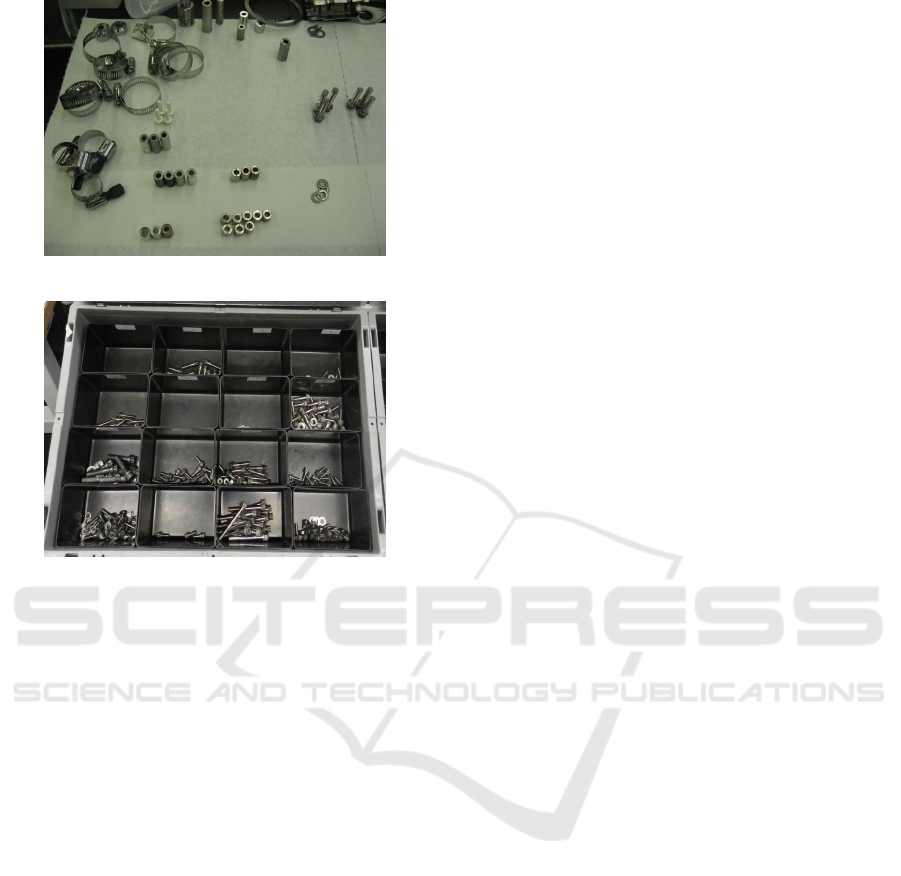
(a)
(b)
Figure 1: Examples of industrial small parts sorted on a
workstation that must be picked (a) and compartments that
contain small parts after packaging (b).
duce time and costs during packaging in overhaul pro-
cesses.
In case of using a pneumatic, hydraulic, or servo-
electric robotic gripper, parts must be picked by a
two-fingered pinch grasp. Therefore, the robot must
receive the orientation of the part and the center point
between its two pinch fingers as the grasp point. Sim-
ilarly, when using a vacuum robotic gripper, small
parts must be picked by a suction cup directly from
the grasp point relative to the orientation of the part.
Therefore, the orientation and grasp point of parts
must be computed.
To the best of our knowledge, the problem of au-
tomating bin picking for packaging in overhaul pro-
cesses has not been studied previously. In this paper,
we propose a method to recognize individual parts au-
tomatically. The method can be used in combina-
tion with a robotic arm to automatically pick parts
and place them into compartments. The proposed
approach uses Mask R-CNN to segment objects and
classify their pose (flat or non-flat) to find pickable
parts and a suitable grasp point. A particular chal-
lenge we address is that parts often occlude each
other. Therefore, we use flat-shaped objects, such as
crank, that stack on each other under ambient light
conditions. However, this method also can be gener-
alized and used for other type of small parts.
2 RELATED WORK
Picking small parts and placing them into specific
containers in overhaul plants can be formulated as a
bin picking problem, where all small parts and fas-
teners are grouped and piled on a specific part of the
workstation. Most industrial bin picking solutions de-
termine the pose of an object and the grasp point by
matching a CAD model to the point cloud obtained
from a 3D sensor. However, many machines use dif-
ferent fasteners produced by different manufacturers
with different CAD models, which may not always be
made available by vendors. In addition, 3D bin pick-
ing solutions, which can operate without CAD models
of objects, can be prohibitively expensive for many
projects. In addition, the characteristics and nature of
industrial fasteners and small parts introduce various
problems, such as reflection and shadow (Taheritan-
jani et al., 2019), which makes fastener picking more
challenging. Finally, using only a single 2D image,
it is impossible to extract the 3D position of objects.
Without any knowledge of the 3D orientation of ob-
jects, robots can only pick the non-occluded parts that
are placed flat relative to the camera lens (Kim et al.,
2012).
The Bin picking approaches can be divided into
two main categories: 1) methods that only compute
grasp points and 2) methods that utilize an object de-
tection framework to find suitable grasp points on the
detected objects. The former provides a heat map that
shows the probability of a successful grasp and se-
lects the highest one. However, such methods require
the orientation of the grasped object. Recently, us-
ing multiple robots in parallel (Levine et al., 2018) or
computing a heat map from artificial grasps in simu-
lations for parallel grippers (Mahler et al., 2017) have
improved object grasping performance.
The latter category attempts to find suitable grasp
locations by estimating the pose of an object and then
extracting grasp points. Numerous bin picking 3D
software applications use such methods to search for
local maxima in a depth map to begin pose estima-
tion of the known object by fitting a CAD model
and determining its pose using a lookup table (Di-
eter Schraft and Ledermann, 2003) (Palzkill and Verl,
2012) (Spenrath et al., 2013). Then, a collision free
path is computed to a predefined grasp location on the
object.
Deep neural networks have been used for pose es-
timation (Do et al., 2018). Brachman et al. described
ICPRAM 2020 - 9th International Conference on Pattern Recognition Applications and Methods
494
a 6D pose estimation system for object instances and
scenes which only needs a single 2D image as in-
put (Brachmann et al., 2016). Wu et al. proposed
to jointly optimize the model learning and pose es-
timation in an end-to-end deep learning framework
(Wu et al., 2019). Their method produces a 3D object
model and a list of rigid transformations to generate
instances to minimize the Chamfer distance.
Object detection and semantic segmentation are
popular topics and many studies have been conducted
in these areas. State-of-the-art results have been pub-
lished using various frameworks, such as Fast R-CNN
(Girshick, 2015), Faster R-CNN (Ren et al., 2015),
and Mask R-CNN (He et al., 2017). Some studies
have used CNNs to solve segmentation tasks for im-
age classification (Wang et al., 2018) (Chen et al.,
2018) (Chen et al., 2017), while others have used
fully convolutional networks (Long et al., 2015) (Noh
et al., 2015). Hema et al., Schwarz et al., and Daniel-
czuk et al. designed segmentation methods for bin
picking tasks (Hema et al., 2007) (Schwarz et al.,
2018) (Danielczuk et al., 2019). Our method consid-
ers two different approaches: 1) using different sec-
tion segmentations to calculate the orientation, i.e.,
different classes must be segmented to compute the
grasp point and determine the orientation or pose of
the object, and 2) using principal component analysis
(Jolliffe, 2011) and Image Moment (Karakasis et al.,
2015) on the detected masks. We demonstrate that
this is especially beneficial for picking small parts
in overhaul processes because, by using 2D image,
we can propose pickable objects to robots with vac-
uum, pneumatic, hydraulic, or servo-electric grippers.
Therefore, our approach is independent of the robotic
gripper and can segment objects to be picked using
only 2D images.
3 DATA COLLECTION
We acquired data from three different cranks. Crank
is part of an axle in gearboxes that is used for convert-
ing reciprocal to circular motion and vice versa. The
images were captured using a fixed monocular cam-
era (Genie Nano GigE) on top of a workstation. For
training and validation, we used 12 grayscale images.
Each image was 1280x1024 pixels and pictured a pile
of cranks on the workstation in ambient light. Fig-
ure 2 shows examples of the images in our dataset.
We annotated each image using the VGG Image
Annotator (Dutta and Zisserman, 2019). For pickable
cranks, we annotated their outer contour and two of
the holes on their surface. Since the robotic arm can
only grasp parts that are not occluded by others and
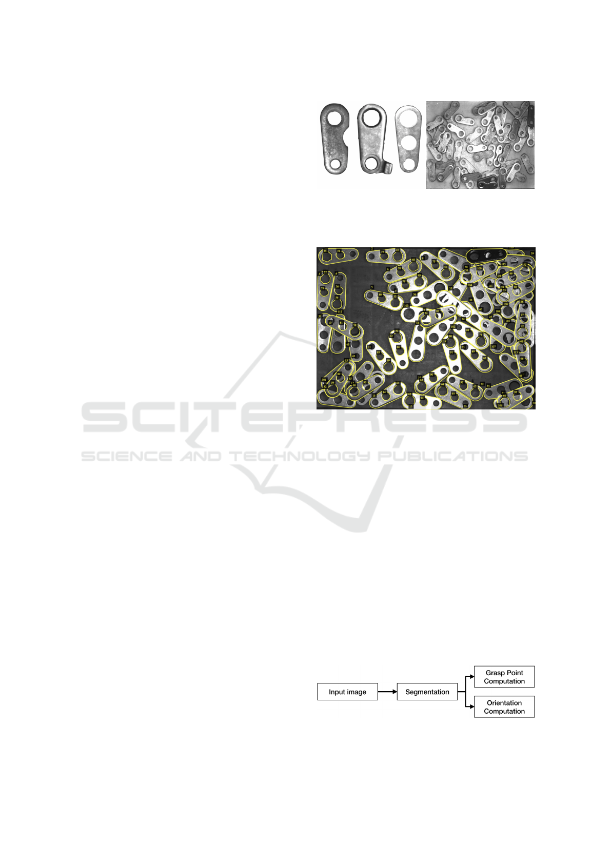
(a) (b)
Figure 2: The datasets contain three different cranks (a).
Example image (b) (each image shows multiple cranks on
the workstation).
Figure 3: Example annotated image in the dataset. While
only the outer contour of unpickable cranks are annotated,
we also annotated two inner holes of pickable instances,
and their outer contour. The pickable and unpickable cranks
were labeled as different classes.
placed flat, we annotated the outer contour of visi-
ble unpickable parts as a different category.Figure 3
shows an example image with annotations from the
dataset.
4 METHOD
A robotic arm requires a grasp point and the orien-
tation of a crank to pick it for packaging; therefore,
we trained a Mask R-CNN model to segment cranks
in the images. Using the cranks’ masks, we computed
the orientation and grasp point of pickable cranks, and
we evaluated the performance of each of these meth-
ods (Figure 4).
Figure 4: Overview of the proposed methods.
2D Orientation and Grasp Point Computation for Bin Picking in Overhaul Processes
495
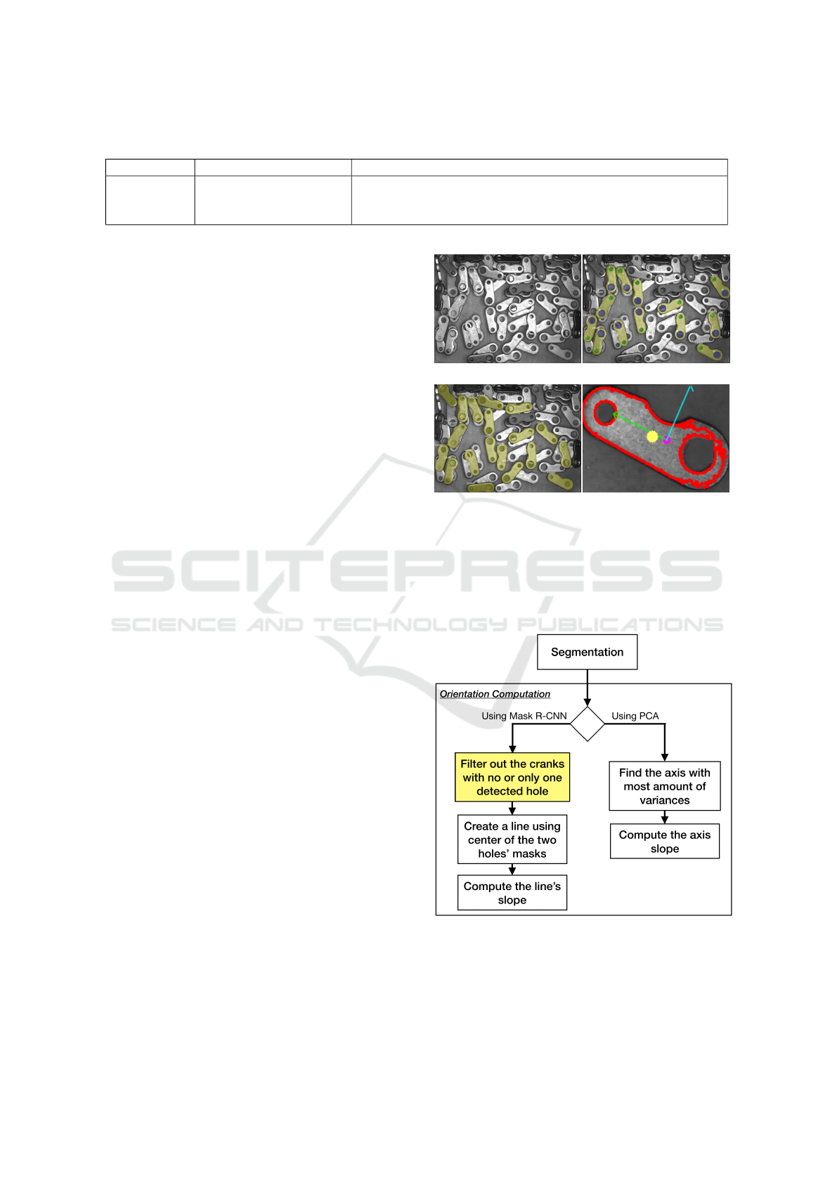
Table 1: Parameters and settings used to train Mask R-CNN model.
# of epochs Learning Rate Augmentations
15 (heads)
45 (all)
0.01 (epochs 1 to 15)
0.001 (epochs 16 to 60)
10% width and height shift, flip left to right, flip up to down,
Blurring, random rotation from 0 to 270
◦
, range of 0.7 to 1.3
light intensity
4.1 Model Training
We used Mask R-CNN with Resnet50 as the network
backbone, and the weights were pretrained using the
COCO dataset (Lin et al., 2014). The models were
trained using a Titan Xp GPU donated by the NVIDIA
Corporation. We used 15% of the dataset for valida-
tion, i.e., two images for each crank. During training,
each pixel was labeled as either background class 0 or
other classes. The error was calculated by finding the
mean over the loss for all classes, and the network was
validated by taking the mean pixel intersection over
union (IoU), with the mean taken over all classes, in-
cluding the background. Table 1 gives an overview of
the training parameters and settings.
For comparison, we trained two types of segmen-
tation models. First, we used images of each crank
to train a model for each crank, i.e., three models for
three different cranks. Second, we used all cranks im-
ages, together to train a single model for all of cranks.
4.2 Segmentation
Using the trained Mask R-CNN models, we seg-
mented the cranks in the images. We annotated pick-
able and unpickable cranks in the train and validation
datasets; thus, the trained models could segment the
pickable cranks. These segmentations were fed into
the next steps to compute the orientation and grasp
point. Figure 5c shows an example of the detected
pickable cranks.
4.3 Orientation Computation
We considered the orientation of a crank as the angle
between the hypothetical horizontal line and the line
between the center of its holes, i.e., the slope of the
line between the center of the holes. For example, all
cranks in Figure 2a have an orientation of 90
◦
. To
compute the orientation of the pickable cranks, we
considered using either Mask R-CNN or PCA (Fig-
ure 6). Note that, we annotated two of the inner holes
of the pickable cranks in our dataset. Therefore, we
can filter the cranks to find their orientation, where the
crank’s outer mask contains two inner holes. To filter
out the masks, we filled the detected masks’ matrices
of the cranks and the detected masks’ matrices of the
(a) Input Image (b) Filtered Masks
(c) Unfiltered Masks (d)
Figure 5: Example original input image (a), the visualiza-
tion of the pickable cranks after filtering the masks, using
only Mask R-CNN (b), and the visualization of all of the
found pickable cranks using Mask R-CNN (c). Using the
results from (c), we apply PCA and Image Moment to find
the orientation (green and blue pivots) and the grasp point
(yellow circle) for the lever on the lower right corner of the
input image (d).
Figure 6: The computation steps to calculate the orientation
of the pickable cranks, using Mask R-CNN or PCA.
holes with 1s, and performed a bitwise OR operation
on them. If their bitwise OR is equal to the detected
mask’s matrix (filled with 1s), the crank mask con-
ICPRAM 2020 - 9th International Conference on Pattern Recognition Applications and Methods
496
Algorithm 1: Filtering out cranks with none or only one hole
detected (marked with yellow in Figures 6 and 7).
1: for crank ROIs do
2: mask ← binary fill holes(crank ROI)
3: pickable
crank
.insert(temp
crank
)
4: pickable
1st
.insert(temp
1st
)
5: pickable
2nd
.insert(temp
2nd
)
6: temp
crank
, temp
1st
, temp
2nd
← null
7: for hole1 ROIs do
8: hole1 mask ← binary fill holes(hole1 ROI)
9: if mask = mask or hole1 mask then
10: temp
crank
← crank ROI
11: temp
1st
← hole1 ROI
12: go out of the loop and continue
13: if temp
crank
is null then
14: continue with the next crank ROI
15: for hole2 ROIs do
16: hole2 mask ← binary fill holes(hole2 ROI)
17: if mask = mask or hole2 mask then
18: temp
2nd
← hole2 ROI
19: go out of the loop and continue
20: if temp
2nd
is null then
21: temp
crank
, temp
1st
← null
tains the hole. Algorithm 1 shows the pseudocode
to filter out cranks with none or only one hole de-
tected. A filtered segmentation mask is shown in Fig-
ure 5b. Detection of the inner holes of the crank make
it possible to calculate its orientation by computing
the slope of the hypothetical line segment between the
center of the masks of the holes.
The other approach to calculate the orientation is
to use principal component analysis (PCA). PCA can
identify two axes that account for the largest amount
of variance in the data (Jolliffe, 2011). Figure 5d visu-
alizes the two axes computed by PCA for an example
crank. By selecting the axis that minimizes the mean
squared distance between the input pixels and their
projection onto it and calculating the axis’s slope, we
can compute the orientation of the crank (the green
axis in Figure 5d).
4.4 Grasp Point Computation
We considered potential grasp point as the middle of
the line segment between the center of crank’s two
holes. For cranks with three holes, we used posi-
tion between their big and middle holes. To compute
the grasp point of pickable cranks, we can use either
Mask R-CNN or Image Moment (Figure 7). In Sec-
tion 4.3, we discussed how we filter out the cranks
with none or only one detected hole. Using the holes’
masks of the pickable cranks, we find the middle point
in the hypothetical line segment between the center of
the holes’ masks, which can be used as a crank’s grasp
point.
The other approach to compute the grasp point is
to use the Image Moment, which is a weighted aver-
age of an image’s pixel intensities. Image Moment
can capture the centroid (geometric center) of the ob-
ject as the statistical properties of the shape, which
can be used as the grasp point of the object. In Fig-
ure 5d, the yellow circle shows the grasp point cal-
culation result obtained using Image Moment for an
example crank.
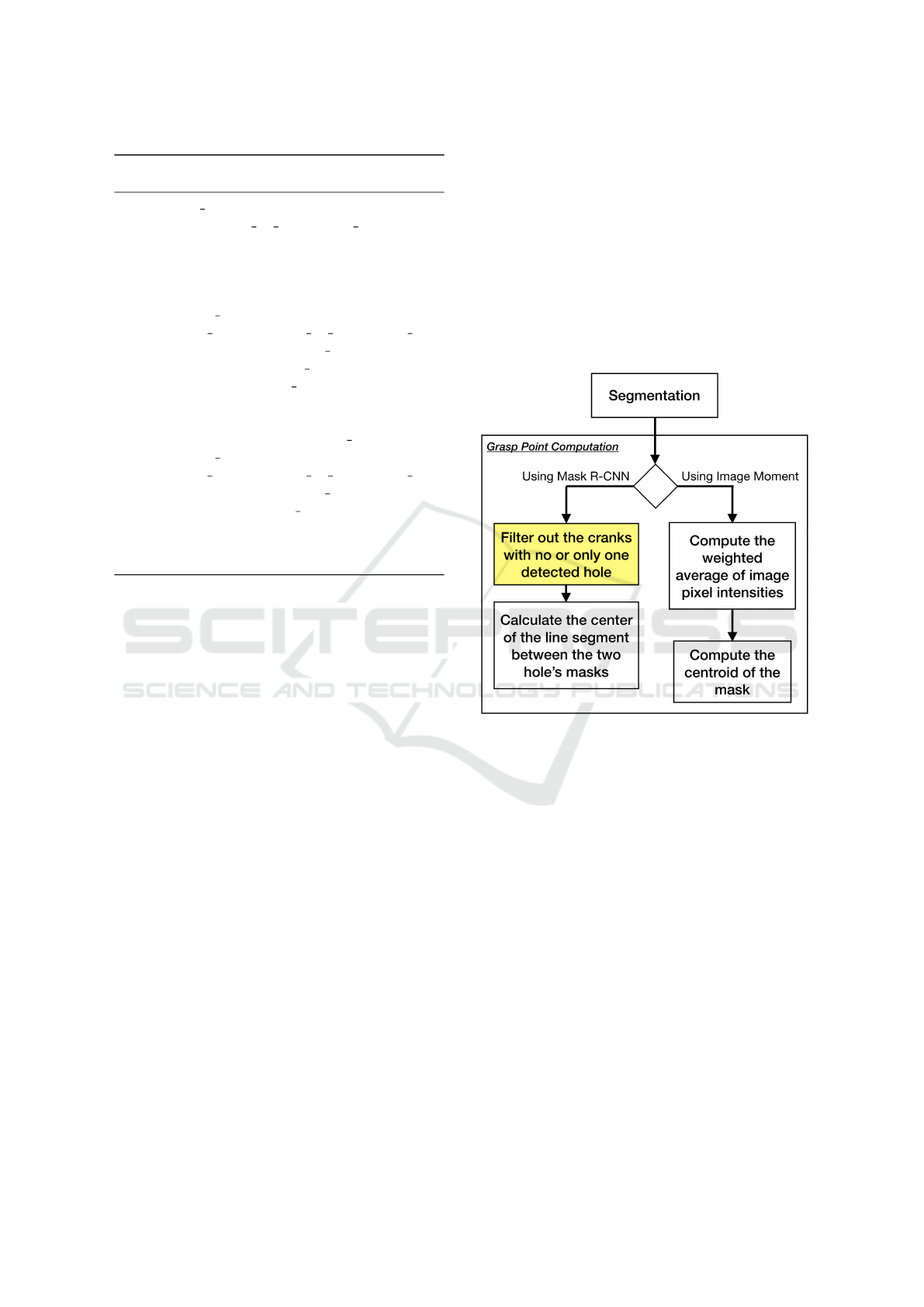
Figure 7: The computation steps to calculate the grasp point
of the pickable cranks, using Mask R-CNN or Image Mo-
ment. The mask filtering algorithm - marked in yellow -
must be calculated only once, for both the orientation and
the grasp point computations.
4.5 Evaluation
To evaluate the proposed approaches, we used a fixed
monocular camera and workstation to capture 20 dif-
ferent images for each crank type (60 images in total).
Each image contained five to 50 cranks laid randomly
on the workspace. In total, these images had 581 pick-
able cranks, which were counted manually to com-
pare and measure the results. We evaluated all im-
ages with the methods discussed in the Sections 4.2,
4.3, and 4.4.
The orientation errors are calculated in rotation
angle (the angle in radian by which the computed ori-
entation must be rotated to reach the actual orienta-
tion). The grasp point errors are the distance between
the computed grasp point and the actual grasp point
(∆d in pixels).
2D Orientation and Grasp Point Computation for Bin Picking in Overhaul Processes
497
In many bin picking studies, the results were com-
pared using the mean IoU (Wang et al., 2018) (Chen
et al., 2018) (Chen et al., 2017). We also used accu-
racy, precision and recall relative to the detected non-
occluded flat laid objects in the images to evaluate the
segmentation results, and we used the mean absolute
error to evaluate the orientation and grasp point com-
putations. The ground truth values for the orientation
and grasp point were acquired manually for compar-
ison. For example, Figure 5a shows 22 cranks that
are not occluded and laid flat on the surface and 38
unpickable cranks (occluded and/or non-flat). In Fig-
ure 5c, the trained Mask R-CNN model detected 16
pickable cranks correctly (true positive) and three in-
correctly (false positive). Therefore, the accuracy of
the segmentation method was 85%. In Figure 5d, the
orientation error is 0.052 radians and the grasp point
error is 13 pixels.
5 RESULTS
Tables 2 and 3 summarize the segmentation, orien-
tation, and grasp point computation evaluation re-
sults. The model trained with all three cranks ob-
tained slightly greater mean IoU compared to in-
dividual models trained using only one crank type.
The model trained with all three cranks demonstrated
higher accuracy, precision and recall than the models
trained with a single crank type.
Using Mask R-CNN to filter out cranks with no or
only detected hole resulted in low accuracy in some
images, especially where there were very few pick-
able cranks in a large pile. Using PCA and Image
Moment to compute the orientation and grasp point
showed a 17% greater percentage of detected pickable
cranks. Despite that, its orientation and grasp point
computation errors were also higher (around three
Table 2: Overview of segmentation results.
# of
crank
types
Mean
IoU
Average
Accuracy
Precision Recall
1 96% 77% 77% 61%
3 97% 80% 79% 69%
times greater for the orientation computation and ap-
proximately two times higher for the grasp point com-
putation).
The method that use PCA and Image Moment to
compute the orientation and grasp point ran up to six
times faster than the Mask R-CNN based method.
Note that we examined calculation time only for com-
parison purposes. The time can differ depending on
different data types, libraries, implementation details,
and hardware.
6 DISCUSSION
The Mask R-CNN approach to compute orientation
and grasp point uses the mask filtering algorithm to
filter out cranks with no or only one detected hole.
One reason for the higher percentage of detected pick-
able cranks using PCA and Image Moment may be
due to the surface of the underlying cranks being vis-
ible through the inner holes of the pickable cranks. In
such cases, the model can fail to detect the holes. In
addition, if we use the Mask R-CNN to compute the
orientation, the crank’s large and small holes are de-
tected as different classes. Therefore, we can always
maintain the same orientation calculation for all pick-
able cranks (the slope of the line, when we start from
the center of big hole towards the center of the small
hole). Using PCA, it is also possible to compute the
orientation towards the big hole, by splitting the crank
relative to the second axis obtained by PCA, and ap-
ply PCA individually on each split. The split that has
a bigger 2nd eigenvalue has also the bigger hole part.
However, the drawback of using PCA is that it may
fail to find the bigger hole, if the surface of the un-
derlying cranks are visible through the small hole of
the pickable cranks. Thus, the relative direction of the
axes to the crank’s big and small holes can be flipped
for different images. In cases where the surface of the
underlying cranks are not visible through the small
hole of the pickable crank, PCA computes one fea-
ture axis towards the big hole. In other case, PCA
may compute one feature axis towards towards the
small hole. The unpredictable calculation of the fea-
ture axis can make this approach not robust for rare
cases, when the robot must place the part in a spe-
Table 3: Overview of orientation and grasp point calculation results.
Approach % of Detected
Pickable Cranks
Orientation
Computation Error
(radian)
Grasp Point
Computation Error
(pixel)
Calculation
Time
(second)
Mask R-CNN 53% 0.033 11 5 to 20
PCA & Image Moment 70% 0.113 21 1 to 3
ICPRAM 2020 - 9th International Conference on Pattern Recognition Applications and Methods
498

cific position in the container. In this case, the Mask
R-CNN based approach can be used, where the de-
tected inner holes’ segments are used to compute the
orientation precisely.
Note that the calculation time has a direct corre-
lation with the number of the cranks in the image.
The Mask R-CNN model requires approximately 20
seconds to find segmentations. The mask filtering
process in Algorithm 1 requires an order of O(n
2
)
to compare filled masks. Therefore, using the de-
tected inner holes to compute the orientation and
grasp point, this approach requires more calculation
time compared to the PCA and Image Moment based
approaches.
We computed PCA and Image Moment on the
ROI of the masks output from Mask R-CNN. Here,
higher orientation and grasp point computation errors
when using PCA and Image Moment is primarily due
to the computations on the entire crank’s ROI rather
than the crank’s Mask. Moreover, the results indicate
that training only one model for all crank types per-
forms better than training a single model per category.
This can be due to having a relatively low amount
of data for the training (only 10 images per crank
type). With only 10 annotated images for training, our
dataset cannot represent all positions and orientations
of the objects in the target environment. Therefore,
more annotated images should be employed to realize
better performance and generalization.
We only used three crank types for this study.
However, the same approach can be employed for
other small parts by identifying the pickability con-
ditions. For example, we decided that cranks must
be placed flat relative to camera lens and their inner
holes must be non-occluded to consider them pick-
able. For bolts, they must placed flat relative to
camera, and in addition, there must be a safe dis-
tance between their contour and surrounding objects
that finger-based grippers can pick them. In addi-
tion, pickability conditions can also be addressed us-
ing keypoint detection of the objects, which has been
introduced in Mask R-CNN. It is also possible to de-
tect the keypoints for the small parts as part of the
training. Study of pickability conditions for different
small parts and performing keypoint detection on the
small parts left for future work.
Many 3D CAD-based solutions
1
enable LED
lightning technology to generate 3D point clouds.
Without relying on these type of sensors, our ap-
proach can cost up to 40 times less. The main draw-
back of the proposed approaches is that objects in the
images must be annotated manually for training. Due
1
https://www.isravision.com/en/ready-to-use/robot-
vision/bin-picking/
to the cluttered order of the objects and noise (light
reflection and shadows), it is very challenging to ob-
tain acceptable annotations using automatic contour
detection methods, such as Canny edge detection (Liu
et al., 2012). However, we can rerun the computa-
tions of the pickable cranks after some are picked by
the robot. Since picking objects from the pile results
in a new scene in the image, it is possible that using
cranks that are no longer occluded may allow us to
obtain new segments for new pickable cranks. There-
fore, the results of this study imply practical usage of
automatic bin picking for packaging in overhaul pro-
cesses.
7 CONCLUSION
In this paper, we have examined the bin picking task
in overhaul processes to automatically place small
parts into containers for reuse. By leveraging Mask R-
CNN for image segmentation, PCA to compute object
orientation, and Image Moment to calculate a possible
grasp point, we have proposed a processing pipeline
that overhaul plants can use to reduce time and cost.
We have presented the results of a preliminary evalu-
ation, and these results demonstrate that the proposed
approach is feasible.
The proposed approach can find 70% of pickable
objects in an image, using only 10 annotated images
for training. Although available commercial solu-
tions, e.g., the 3D, stereo, and laser solutions, show
better accuracy, the proposed approach could be used
as a practical solution for low-budget bin picking in
overhaul processes.
REFERENCES
Brachmann, E., Michel, F., Krull, A., Ying Yang, M.,
Gumhold, S., et al. (2016). Uncertainty-driven 6d
pose estimation of objects and scenes from a single
rgb image. In Proceedings of the IEEE Conference
on Computer Vision and Pattern Recognition, pages
3364–3372.
Chen, L.-C., Papandreou, G., Kokkinos, I., Murphy, K., and
Yuille, A. L. (2017). Deeplab: Semantic image seg-
mentation with deep convolutional nets, atrous convo-
lution, and fully connected crfs. IEEE transactions on
pattern analysis and machine intelligence, 40(4):834–
848.
Chen, L.-C., Zhu, Y., Papandreou, G., Schroff, F., and
Adam, H. (2018). Encoder-decoder with atrous sepa-
rable convolution for semantic image segmentation. In
Proceedings of the European conference on computer
vision (ECCV), pages 801–818.
2D Orientation and Grasp Point Computation for Bin Picking in Overhaul Processes
499

Danielczuk, M., Matl, M., Gupta, S., Li, A., Lee, A.,
Mahler, J., and Goldberg, K. (2019). Segmenting
unknown 3d objects from real depth images using
mask r-cnn trained on synthetic data. In 2019 In-
ternational Conference on Robotics and Automation
(ICRA), pages 7283–7290. IEEE.
Dieter Schraft, R. and Ledermann, T. (2003). Intelligent
picking of chaotically stored objects. Assembly Au-
tomation, 23(1):38–42.
Do, T.-T., Cai, M., Pham, T., and Reid, I. (2018). Deep-
6dpose: Recovering 6d object pose from a single rgb
image. arXiv preprint arXiv:1802.10367.
Dutta, A. and Zisserman, A. (2019). The via annotation
software for images, audio and video. arXiv preprint
arXiv:1904.10699, 5.
Girshick, R. (2015). Fast r-cnn. In Proceedings of the IEEE
international conference on computer vision, pages
1440–1448.
He, K., Gkioxari, G., Doll
´
ar, P., and Girshick, R. (2017).
Mask r-cnn. In Proceedings of the IEEE international
conference on computer vision, pages 2961–2969.
Hema, C. R., Paulraj, M., Nagarajan, R., and Sazali, Y.
(2007). Segmentation and location computation of bin
objects. International Journal of Advanced Robotic
Systems, 4(1):9.
Jolliffe, I. (2011). Principal component analysis. Springer.
Karakasis, E. G., Amanatiadis, A., Gasteratos, A., and
Chatzichristofis, S. A. (2015). Image moment invari-
ants as local features for content based image retrieval
using the bag-of-visual-words model. Pattern Recog-
nition Letters, 55:22–27.
Kim, K., Kim, J., Kang, S., Kim, J., and Lee, J.
(2012). Vision-based bin picking system for indus-
trial robotics applications. In 2012 9th International
Conference on Ubiquitous Robots and Ambient Intel-
ligence (URAI), pages 515–516. IEEE.
Levine, S., Pastor, P., Krizhevsky, A., Ibarz, J., and Quillen,
D. (2018). Learning hand-eye coordination for robotic
grasping with deep learning and large-scale data col-
lection. The International Journal of Robotics Re-
search, 37(4-5):421–436.
Lin, T.-Y., Maire, M., Belongie, S., Hays, J., Perona, P.,
Ramanan, D., Doll
´
ar, P., and Zitnick, C. L. (2014).
Microsoft coco: Common objects in context. In Euro-
pean conference on computer vision, pages 740–755.
Springer.
Liu, M.-Y., Tuzel, O., Veeraraghavan, A., Taguchi, Y.,
Marks, T. K., and Chellappa, R. (2012). Fast ob-
ject localization and pose estimation in heavy clutter
for robotic bin picking. The International Journal of
Robotics Research, 31(8):951–973.
Long, J., Shelhamer, E., and Darrell, T. (2015). Fully con-
volutional networks for semantic segmentation. In
Proceedings of the IEEE conference on computer vi-
sion and pattern recognition, pages 3431–3440.
Mahler, J., Liang, J., Niyaz, S., Laskey, M., Doan, R., Liu,
X., Ojea, J. A., and Goldberg, K. (2017). Dex-net
2.0: Deep learning to plan robust grasps with synthetic
point clouds and analytic grasp metrics. arXiv preprint
arXiv:1703.09312.
Noh, H., Hong, S., and Han, B. (2015). Learning de-
convolution network for semantic segmentation. In
Proceedings of the IEEE international conference on
computer vision, pages 1520–1528.
Palzkill, M. and Verl, A. (2012). Object pose detection in
industrial environment. In ROBOTIK 2012; 7th Ger-
man Conference on Robotics, pages 1–5. VDE.
Ren, S., He, K., Girshick, R., and Sun, J. (2015). Faster
r-cnn: Towards real-time object detection with region
proposal networks. In Advances in neural information
processing systems, pages 91–99.
Schwarz, M., Milan, A., Periyasamy, A. S., and Behnke,
S. (2018). Rgb-d object detection and semantic seg-
mentation for autonomous manipulation in clutter.
The International Journal of Robotics Research, 37(4-
5):437–451.
Spenrath, F., Palzkill, M., Pott, A., and Verl, A. (2013).
Object recognition: Bin-picking for industrial use. In
IEEE ISR 2013, pages 1–3. IEEE.
Taheritanjani, S., Haladjian, J., and Bruegge, B. (2019).
Fine-grained visual categorization of fasteners in
overhaul processes. In 2019 5th International Confer-
ence on Control, Automation and Robotics (ICCAR),
pages 241–248. IEEE.
Taheritanjani, S., Schoenfeld, R., and Bruegge, B. Auto-
matic damage detection of fasteners in overhaul pro-
cesses.
Wang, P., Chen, P., Yuan, Y., Liu, D., Huang, Z., Hou, X.,
and Cottrell, G. (2018). Understanding convolution
for semantic segmentation. In 2018 IEEE winter con-
ference on applications of computer vision (WACV),
pages 1451–1460. IEEE.
Wu, Y., Marks, T., Cherian, A., Chen, S., Feng, C., Wang,
G., and Sullivan, A. (2019). Unsupervised joint 3d ob-
ject model learning and 6d pose estimation for depth-
based instance segmentation. In Proceedings of the
IEEE International Conference on Computer Vision
Workshops, pages 0–0.
ICPRAM 2020 - 9th International Conference on Pattern Recognition Applications and Methods
500
