
Generating a Consistent Global Map under Intermittent Mapping
Conditions for Large-scale Vision-based Navigation
Kazuki Nishiguchi
1
, Walid Bousselham
2
, Hideaki Uchiyama
1 a
, Diego Thomas
1 b
,
Atsushi Shimada
1
and Rin-ichiro Taniguchi
1 c
1
Kyushu University, Fukuoka, Japan
2
ENSTA ParisTech, Paris, France
nishiguchi@limu.ait.kyushu-u.ac.jp, walid.bousselham@ensta-paristech.fr,
Keywords:
Visual SLAM, Global Localization, Map Merging, Navigation.
Abstract:
Localization is the process to compute sensor poses based on vision technologies such as visual Simultaneous
Localization And Mapping (vSLAM). It can generally be applied to navigation systems . To achieve this, a
global map is essential such that the relocalization process requires a single consistent map represented with
an unified coordinate system. However, a large-scale global map cannot be created at once due to insufficient
visual features at some moments. This paper presents an interactive method to generate a consistent global
map from intermittent maps created by vSLAM independently via global reference points. First, vSLAM is
applied to individual image sequences to create maps independently. At the same time, multiple reference
points with known latitude and longitude are interactively recorded in each map. Then, the coordinate system
of each individual map is converted into the one that has metric scale and unified axes with the reference points.
Finally, the individual maps are merged into a single map based on the relative position of each origin. In the
evaluation, we show the result of map merging and relocalization with our dataset to confirm the effectiveness
of our method for navigation tasks. In addition, the report on participating in the navigation competition in a
practical environment is also discussed.
1 INTRODUCTION
The technology essential to the development of nav-
igation systems and autonomous robots is localiza-
tion. Localization is the process of estimating the
location of a sensor in a specific coordinate system.
Particularly, global localization is the estimation of
the longitude and latitude of a location in the World
Geodetic System (WGS) within the field of naviga-
tion. Global navigation satellite system (GNSS) is
widely used in outdoor navigation systems because
it only needs an antenna to receive signals (Hofmann-
Wellenhof et al., 2007). To increase the frequency
of the localization outputs, inertial measurement units
(IMU) with high frame rates are incorporated in such
systems, referred to as an inertial navigation system
(INS) (Farrell, 2008). For instance, an image se-
quence and its their global positions from the INS
a
https://orcid.org/0000-0002-6119-1184
b
https://orcid.org/0000-0002-8525-7133
c
https://orcid.org/0000-0002-2588-6894
were recorded while driving to generate Google Street
View (Anguelov et al., 2010). Generally, the localiza-
tion techniques used in existing navigation systems
for pedestrians and vehicles focus on estimating 2D
coordinates on a map to provide, for instance, a route
to a destination. To estimate the height and heading, a
barometer and a magnetic sensor can be coupled with
such systems (Parviainen et al., 2008).
Vision-based approaches have been proposed to
increase the degrees of freedom (DoF) for sensor
poses because they can compute both 3 DoF for posi-
tion and 3 DoF for orientation to represent any rigid
motion in 3D space. Such approaches are based on
online 3D reconstruction and camera pose estima-
tion using visual SLAM (vSLAM) (Taketomi et al.,
2017). With 6 DoF of navigation, the range of ap-
plications can be enhanced such that a precise view-
ing direction in 3D space can be provided as a guid-
ance. For instance, the software libraries for de-
veloping AR systems such as the ARKit by Apple
or ARCore by Google are used to develop a navi-
gation system for small indoor spaces (Corotan and
Nishiguchi, K., Bousselham, W., Uchiyama, H., Thomas, D., Shimada, A. and Taniguchi, R.
Generating a Consistent Global Map under Intermittent Mapping Conditions for Large-scale Vision-based Navigation.
DOI: 10.5220/0008968207830793
In Proceedings of the 15th International Joint Conference on Computer Vision, Imaging and Computer Graphics Theory and Applications (VISIGRAPP 2020) - Volume 4: VISAPP, pages
783-793
ISBN: 978-989-758-402-2; ISSN: 2184-4321
Copyright
c
2022 by SCITEPRESS – Science and Technology Publications, Lda. All rights reser ved
783

Irgen-Gioro, 2019). Compared with GNSS-based ap-
proaches, camera-based ones require pre-processing
to generate a map database containing images associ-
ated with their poses (Williams et al., 2011; Kendall
et al., 2015). For the localization process, an input
image is first matched to the images in the database
by using an image retrieval technique (G
´
alvez-L
´
opez
and Tardos, 2012), then the pose of a matched im-
age is used as the estimated pose of the input image.
This process is specifically referred to as relocaliza-
tion within the field of computer vision.
To achieve relocalization, the most important task
is to generate a consistent map database containing all
the image poses that are represented by the same co-
ordinate system. However, in various practical situa-
tions, it is difficult to map all parts of a target environ-
ment at once because mapping cannot be performed
with insufficient visual features. In other words, the
mapping process can be intermittent in a large-scale
environment such that each map is individually gen-
erated with its own coordinate system. This happens
especially in indoor environments due to texture-less
human-made objects in corridors or near stairs. Merg-
ing multiple discontinuous maps is a crucial problem
practically, and is not well-investigated in the litera-
ture.
To solve the aforementioned issue, this paper
presents a method for generating a consistent global
map under intermittent mapping conditions with
sparse reference points which longitude and latitude
are known. The main idea was originally designed
for participation in the competition for large-scale
seamless indoor and outdoor localization tasks held
at IPIN2019
1
. In the competition, which was based
on the EvAAL framework (Potort
`
ı et al., 2017), the
primary task was to answer the longitude and latitude
of given locations in the both indoor and outdoor envi-
ronments. As a preparation, sparsely-distributed ref-
erence points were provided or were able to be mea-
sured in the environment by ourselves to calibrate the
system. Investigating longitude and latitude on a map
is easily achieved by using standard Geographic In-
formation System (GIS) software. If all the reference
points are represented in the WGS, individual maps
can be merged via the reference points. In this paper,
we propose a step-by-step procedure to first generate
individual maps and then merge them in the unified
coordinate system for global navigation from a prac-
tical development point-of-view. This is equivalent
to developing GIS-supported vision-based navigation
systems. Also, we provide the report on the naviga-
tion competition where we participated in by devel-
oping a vision-based navigation system.
1
http://ipin2019.isti.cnr.it/
2 RELATED WORK
Generally, standard vSLAM systems can support a
continuously-generated map for relocalization (Mur-
Artal et al., 2015). However, merging multiple maps
is a practical and crucial problem for large-scale
vision-based navigation. In the literature, the ap-
proaches can be summarized into two categories.
To merge multiple maps into the same coordi-
nate system, one approach is based on the fact that
each map contains the same region in the environ-
ment (Zou and Tan, 2012; McDonald et al., 2013).
In this case, the maps can be easily merged by using
the shared feature points of the region. If the shared
points exist, the 3D transformation matrix to merge
two maps is computed by using the 3D coordinates
represented in each map coordinate system. This idea
was generally used for mapping the environment with
collaborative robots or drones.
As the second approach, a technique of map merg-
ing was investigated for developing augmented reality
applications (Castle et al., 2008). Basically, the anno-
tations are required to be associated with each map
independently such that the associated annotation is
visualized only when the map is visible. In other
words, it is not necessary to represent all the maps
in the same coordinate system even though all of the
maps were incorporated into one system in some way.
Therefore, AR systems do not always need the abso-
lute positions for placing and visualizing AR annota-
tions because the annotations can be placed relatively
with each map.
Compared to the existing approaches, we focus on
representing multiple discontinuous maps into one in
the unified coordinate system when each map does
not share the same regions. As aforementioned, this
problem occurs in various situations such as buildings
or large-scale environments. To solve this problem,
we propose to utilize sparse global reference points
for each map, given by GIS, as a prior to merge mul-
tiple maps into the same coordinate system.
3 PROPOSED METHOD
Reconstructing a large scale environment based vi-
sual information cannot be always performed at once
due to the lack of the visual features. In particu-
lar, indoor environments, such as a narrow texture-
less corridor, often contain conditions that make the
tracking process in vSLAM fail. In addition, it is
inevitable that the camera moves with large rotation
while turning corners and climbing stairs in indoor
navigation systems, as discussed in Section 6. This
VISAPP 2020 - 15th International Conference on Computer Vision Theory and Applications
784

also makes vSLAM fail even with visual-inertial ap-
proaches. Therefore, maps needs to be intermittently
generated in practice. To combat this issue, we pro-
pose a method for the creation of multiple small maps
and their merger via global reference points.
3.1 Prerequisite
Our basic idea to merge multiple maps into one map
is to represent each map in the WGS directly. In other
words, some global reference points are required to
be acquired when generating each map. This process
is designed based on the following reason.
Generally, GNSS signals are not accurately re-
ceived in indoor environments due to obstacles that
make the signals attenuate. Outdoor environments
also causes similar results, especially in urban regions
with buildings. Therefore, the assumption that global
positioning signals are available is not always valid.
Instead, we aim mainly at the situation that we
can utilize sets of sparse global positions that can be
pre-calibrated as some reference points. For instance,
such points are placed in the indoor layout map used
when building them. Also, some landmarks can have
global coordinate in outdoor environments In this pa-
per, we use GIS to generate such landmarks from
satellite images. Even though this may not be a gen-
eralized situation and our solution is straightforward,
this can be practically achieved in several situations,
as organized in the competition for navigation. There-
fore, we utilize this prerequisite as a prior for map
merging.
3.2 Overview
We first summarize the flow of our proposed frame-
work, as illustrated in Figure 1. The procedure for
generating a consistent global map from small sub-
maps can be divided into the following three steps:
1. Map creation with reference point selection
2. Map conversion with reference points
3. Map merging
As mentioned above, the longitude and latitude at
some positions in the environment are given in our
prior condition, as referred to as global reference
points.
In the 1st step, the map is reconstructed by us-
ing vSLAM. This operation is performed in several
small areas in the environment, each of which does
not have to be continuous. In addition, the location
of the global reference points, which are presented in
the WGS, is required to be recorded in parallel to vS-
LAM.
In the 2nd step, the coordinate system of each map
generated in the 1st step is aligned in terms of scale
and orientation. This is because each map is repre-
sented in an unknown individual vSLAM coordinate
system. This process is necessary to simplify the lat-
ter process of merging maps.
In the 3rd step, the individual maps are merged
by shifting the origin of each individual coordinate
system into the WGS. Finally, all the individual maps
are represented in the same coordinate system.
Through these steps, we can obtain an actual
scaled global map. Once the map is obtained, it can
be applied to any navigation system by performing
the relocalization process in vSLAM. The overview
of our global navigation system is introduced in Fig-
ure 2. Two individual maps that do not share the same
region are merged by our proposed method. Then, re-
localization is used to estimate the location of an user
for a navigation task.
3.3 Map Creation
This process is generally based on vSLAM to gen-
erate feature points and images associated with their
pose in each vSLAM coordinate system. Here, we de-
scribe how to interactively record the reference points
with known latitude and longitude, in parallel to vS-
LAM, as illustrated in Figure 1(a). The detail of our
vSLAM architecture for our global navigation system
is explained in Section 4.
Each time users reach the location of a refer-
ence point during mapping, the pose at the reference
point in the vSLAM coordinate system and the fea-
ture points observed in the image are saved in associ-
ation with the latitude and longitude. If the height at
the reference point is available, for instance, at multi-
floor buildings, height is also saved. In our imple-
mentation, each reference point has identification data
(ID) such that a list of reference points is prepared in
advance, as illustrated in Figure 3. At the reference
point, it is necessary for users to assign the ID of each
reference point with an image.
Generally, we assume that the reference points are
provided as some landmarks beforehand, as described
in Section 3.1. If necessary, this procedure can be
easily performed by using a standard GIS software
2
,
which is typically used in navigation systems. This
interactive process is independent of the vSLAM so
that any GIS software and vSLAM methods can be
used. It should be noted that at least 3 reference points
must be saved for each map.
2
https://www.qgis.org
Generating a Consistent Global Map under Intermittent Mapping Conditions for Large-scale Vision-based Navigation
785
Images
vSLAM with ref points selection
Map
Ref points
(a) Map creation
Map
Scaling
Converted Map
Shifting origin
Rotating
Ref points
(b) Map conversion
Converted
Map1 origin
Merging
map components
Merged map
Converted Map2
Shifting origin
Shifted Map2
Converted Map1
(c) Map merging
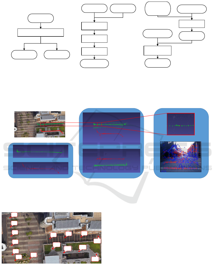
Figure 1: Flow of each step in our proposed method. (a) shows the flow of map creation. By using vSLAM, the map is
generated. In addition, the reference points are recorded interactively. (b) shows the flow of map conversion. Based on the
reference points, the coordinate system of each map is converted through three steps: shifting origin, scaling, and rotating. (c)
shows the flow of map merging. Based on the relative positions between the origins of the converted maps, all of the maps
are merged by shifting them to the WGS.
Reconstructed maps
map1
map2
Two individual paths
Top view
Side view
Navigation
by relocalization and tracking
Merged maps
Scene view
Estimated pose
Figure 2: Overview of our global navigation system. First, the maps are reconstructed independently. Then, these maps are
merged into one by our proposed method. After that, relocalization is performed on the merged map for navigation. Red dots
represent the feature points in the map database, and blue ones are not in the database in the scene view.
1
2
0
3
4
5
6
7
8
9
10
11
12
13
14
Figure 3: Reference points. Reference points and their ID
are illustrated. Using a standard GIS software, the latitude
and longitude at any point on the map can be created easily.
3.4 Map Conversion
In this section, we explain how to compute the trans-
formation from each vSLAM coordinate system to
the aligned one, as illustrated in Figure 1(b). The
overview of the computation process is illustrated in
Figure 4. This operation is performed for each small
map obtained by vSLAM, as explained in Section 3.3.
3.4.1 Shifting Origin
The origin of the map is automatically determined
when vSLAM is initialized such that the initial cam-
era coordinate system is used as the vSLAM coor-
dinate system (Mur-Artal et al., 2015). It is helpful
if the latitude and longitude of the origin of the vS-
VISAPP 2020 - 15th International Conference on Computer Vision Theory and Applications
786

LAM coordinate system are known to simplify later
processes. Therefore, we first set the origin of the
vSLAM coordinate system at one of the reference
points. More concretely, the inverse pose at a refer-
ence point is multiplied with other poses and feature
points so that the origin can be set to the reference
point.
3.4.2 Scaling
With monocular vSLAM, the scale is unknown, and is
determined such that the distance between two initial
positions is one. Even with IMU, the scale factor may
not be accurately computed or be drifted due to noise.
Therefore, we propose to scale the map with global
reference points, as an alternative approach.
If we know the metric distance between 2 refer-
ence points, we can perform the scaling. The dis-
tance, in meters, can be calculated from the latitude
and longitude between two reference points with GIS
software. At two reference points, the scale is calcu-
lated as the ratio between the distance in meters and
that in the vSLAM coordinate system. Furthermore,
the scaling parameter is calculated by taking the aver-
age of multiple ratios as follows.
d
i
= ||p
0
re f
− p
i+1
re f
||
D
i
= ||P
0
re f
− P
i+1
re f
||(i ∈ [0, N − 1])
(1)
s =
N−1
∑
i=0
D
i
d
i
(2)
where N is the number of reference points, p
i
re f
and
P
i
re f
are the position of i-th reference points in the
vSLAM coordinate system and in the WGC, respec-
tively. Also, d
i
and D
i
are the distances from the ori-
gin of the i-th reference points in the vSLAM coor-
dinate system and in the WGC, and s is a scaling pa-
rameter.
3.4.3 Rotating
The orientation of each scaled vSLAM coordinate
system is aligned by this process. In this process, the
unified coordinate system for all the maps is defined
as follows: the direction of each x-axis is set to that
along the meridian, and that of z-axis faces the equa-
tor direction.
Let R
x
(α), R
y
(β) and R
z
(γ) be rotation matrices
against each axis and α, β, and γ be their angles, re-
spectively. Assuming that the rotated result of the
vSLAM coordinate system with the rotation matri-
ces corresponds to the unified coordinate system, the
movement on the x-axis of the vSLAM coordinate
system can be converted into the movement on the
meridian direction, and the z-axis is on the equator
direction. Then, the latitude and longitude can be
calculated from the x and z components of the ref-
erence point in the scaled and rotated vSLAM coordi-
nate system.
The rotation matrix can be obtained by the fol-
lowing optimization. First, rotation angles α, β, and
γ is given to initialize a rotation matrix. Next, the x
and z components of the reference points in the coor-
dinate system transformed by the rotation matrix are
converted into latitude and longitude by using meters
to degrees translation. Then, by comparing the error
between the estimated one and the actual one given at
the reference point, and the residuals can be defined
for the optimization. Since these residues depends on
α, β, and γ angles, we can solve this by the non-linear
least squares problem with the following equations.
Res
lat
(α, β, γ) = Lat
actual
− Lat
estimated
(α, β, γ)
Res
lon
(α, β, γ) = Lon
actual
− Lon
estimated
(α, β, γ)
(3)
min
α,γ∈[−180
◦
,180
◦
]
β∈[−90
◦
,90
◦
]
1
2
N−1
∑
i=0
||Res
lat
2
+ Res
lon
2
||
2
(4)
where N is the number of reference points. Due to the
range of the parameters, the initial angles may need to
be set appropriately such that the camera view direc-
tion is initially parallel to the ground. In our system,
the optimization was implemented using the Ceres
solver
3
.
3.5 Map Merging
In this section, the maps created individually are
merged into one map. Owing to the two former pro-
cesses, we were able to obtain multiple independent
maps with the same scale and the same axis orienta-
tion. Therefore, it is possible to merge the maps with
only focusing on shifting the positional relationship
of the origin of each coordinate system, as illustrated
in Figure 1(c).
3.5.1 Shifting Origin
The origin of each map corresponds to a reference
point used for the shifting, as explained in Sec-
tion 3.4.1. The base map is first selected from one
of the individual maps. Then, by shifting the entire
map based on the relative position between the base
origin and the other map origins, the coordinate sys-
tem of the other map is converted to that of the base
map.
3
http://ceres-solver.org
Generating a Consistent Global Map under Intermittent Mapping Conditions for Large-scale Vision-based Navigation
787
Z
X
Y
Longitude
Latitude
Equator
Prime
Meridian
Shifting Origin
Z
X
Y
Longitude
Latitude
Prime
Meridian
Equator
Scaling
Shifted/Scaled/
Rotated Coord
Shifted/Scaled Coord
Shifted Coord
vSLAM Coord
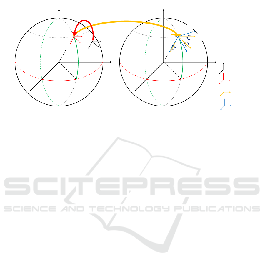
Figure 4: Map conversion. First, the vSLAM coordinate system in black is convert into the red one by shifting origin. Next,
the red one is converted into yellow one by scaling. Finally, the yellow one is converted into blue one by rotating.
3.5.2 Merging Map Component
With the above operation, the map representation has
been converted to the same coordinate and origin.
Therefore, merging individual maps created indepen-
dently is completed by combining the map compo-
nents together.
4 IMPLEMENTATION DETAILS
OF VSLAM
In this section, we describe the details of the vSLAM
implementation used to create the map for our navi-
gation system.
4.1 Feature Choice
The first thing to do when performing feature
point-based vSLAM is feature choice. In ORB-
SLAM(Mur-Artal et al., 2015), which is one of the
state-of-the-art approaches of vSLAM, ORB is se-
lected because of the speed of detection. In fact, ORB
detection is extremely fast compared to other features
and is suitable for real-time operation. However, the
repeatability or stability is sometimes not enough for
stable vSLAM.
We compared the ORB and AKAZE features (Al-
cantarilla and Solutions, 2011) in terms of feature de-
tection stability. As a result, in outdoor environments,
where there are enough textures, there was no sig-
nificant difference. However, in indoor environments
where there are less textures, ORB occasionally can-
not detect the stable features between two consecutive
images in practice. It is an indispensable requirement
to detect the same feature stably to maintain the track-
ing function. Therefore, we selected AKAZE as the
feature used in our system. To guarantee real-time
operation, we have reduced the resolution of the in-
put image. This is the trade-off between the compu-
tational cost and stability. Even though we used the
lower resolution, the accuracy was not drastically de-
graded for the navigation tasks.
4.2 Map Components
In terms of vSLAM architecture, our system mostly
refers to ORB-SLAM and the map is represented by
keyframes and 3D map points. The main difference
is the data for global reference points. We used two
main structures, which were divided into a map struc-
ture and frame structure, for our map merging. The
elements of frame structure are as follows:
• 3D-pose in vSLAM coordinate system
• Observed feature point descriptor, its coordinates
on the image plane, and whether the point has
been reconstructed or not
• Bag of visual words (BoVW) feature vector of the
frame
• Latitude, longitude and height in metric world
scale at reference points
• A list of keyframes that observe feature points
common for other frames. This defines the scope
of local Bundle Adjustment (BA).
The elements of map structure are as follows:
• A list of frame structures reconstructed as
keyframes
VISAPP 2020 - 15th International Conference on Computer Vision Theory and Applications
788

• A list of reconstructed 3D points, its coordinates
in the vSLAM coordinate system, and keyframes
observing each of them
• Latitude, longitude, and height at map origin in
the metric world scale
4.3 Matching Method
As similar to other vSLAM methods based on
PTAM (Klein and Murray, 2007), our system has
three functions: tracking, mapping and bundle adjust-
ment. As mentioned earlier, most of our system fol-
lows ORB-SLAM(Mur-Artal et al., 2015). Specifi-
cally, some changes have been made to the method of
feature point matching in the tracking and mapping
for further stability in both indoor and outdoor envi-
ronments.
The basic idea of matching in ORB-SLAM is to
increase the reliability of matching by giving spatial
constraints to candidate feature points that are to be
matched. In addition to this idea, we used GMS (Bian
et al., 2017) as a means to further give the constraint to
matching. This reinforces the concept of emphasizing
spatial information between feature points.
5 EVALUATION
To investigate the performance of our proposed
method, we show the results of map merging and relo-
calization with our dataset taken at our campus. As a
prototype of handheld navigation systems, the pedes-
trian captured images while having the laptop with a
monocular web camera facing to the moving direc-
tion.
5.1 Dataset
For the map database, we captured image sequences
at three discontinuous paths with different level of
floors, as illustrated in Figure 5(a). The reference
points were placed, as illustrated in Figure 3.
For the relocalization task, we captured the image
sequence on the other day. The path was designed to
include both the path in the database and the one in
unknown regions, as illustrated in Figure 6(a). The
color on the path is coded in the order of time series
from red, blue, green, yellow, and white.
5.2 Result of Map Merging
Figure 5 illustrates both the paths used for the map
database and the merged map. By comparing Fig-
ure 5(a) and (b), the trajectory in the merged map
was approximately same as the paths used for the map
database. In addition, as illustrated in Figure 5(c), the
merged map contains the discontinuous levels of the
floors. Therefore, it can qualitatively be confirmed
that the intermittently-generated maps have been suc-
cessfully merged.
5.3 Result of Relocalization
Next, we present the relocalization result with the
merged map for navigation tasks. To visualize the
estimated longitude and latitude, we used Google
Earth
4
that takes the KML file converted from the logs
of latitude and longitude.
From Figure 6(b), it can be observed that that red
dots are scattered in places far from the actual path.
This noisy results occurred during the relocalization.
This means that it may have been caused by attempt-
ing to relocalize with another scene due to unsuccess-
ful image retrieval. Next, the path shown in blue dots
was correctly estimated owing to tracking after relo-
calization. In the green dots, some inaccurate results
were observed at the right side of the image. Sim-
ilar to the failure in the relocalization process, there
was a moment when tracking was lost during rotat-
ing the camera. At this moment, the relocalization
was performed again, and sometimes failed due to
the low accuracy of image retrieval. In addition, the
green, yellow, and a part of white dots were captured
at unknown paths that have not been mapped. Unless
tracking was lost, vSLAM created a new map so that
the latitude and longitude were computed. Finally, in
the last part of the white dots, the trajectory was ac-
curately recovered. This is because the result of the
relocalization with the known map.
5.4 Limitation
The above results showed that the localization for
navigation tasks can be estimated by relocalization
and vSLAM. However, the scale drift was observed
in the yellow dots although the estimated paths were
approximately same as the actual ones. These dots
represent the path that were not included in the map
database. This is basically a fundamental problem of
monocular visual odometry. To avoid this problem,
the navigation task to be applied needs to have a route
determined in advance so that the all of the maps for
navigation should be prepared.
4
https://www.google.com/earth/
Generating a Consistent Global Map under Intermittent Mapping Conditions for Large-scale Vision-based Navigation
789
(a) Paths for map database
(b) Top view of reconstructed maps (c) Side view of reconstructed maps
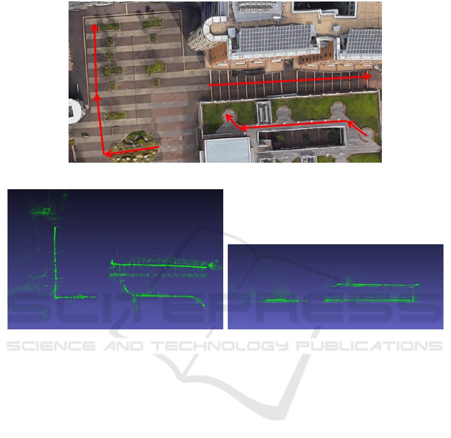
Figure 5: Result of reconstructed maps in our campus. (a) represents paths when creating the map database. The approximate
scale of the image is 120 by 70 square meter. (b) and (c) are top and side views of the merged map. The estimated paths
qualitatively matched the actual paths.
6 PARTICIPATION IN THE
NAVIGATION COMPETITION
As an attempt to apply our method to realistic prob-
lems, we participated in track 2 of the competition
held at IPIN2019. This competition focused on evalu-
ating the accuracy of both indoor and outdoor naviga-
tion systems that answered the longitude and latitude
of given locations. The user of our system was pre-
pared by the organizers. To participate in the compe-
tition, we selected a monocular camera only as a sim-
plest sensor configuration. Our strategy was to build a
map of the venue on the survey and setup day that was
scheduled one day before the competition, and then
to use relocalization and vSLAM on the competition
day. Compared with benchmarking datasets for vehi-
cles and drones, this competition focused on handheld
indoor and outdoor navigation systems, and clarified
some specific problems for this issue as follows:
• Time Needed for Creating Map Database.
Before the competition, the path for the competi-
tion was closed. Only the entire venue that could
be passed by the pedestrian was disclosed. There-
fore, we needed to reconstruct all of the environ-
ment in advance.
Figure 7 illustrates the aerial photo of the compe-
tition venue and the map we reconstructed. The
venue was approximately 170 by 200 square me-
ter with three floor levels. With our proposed
method, the venue was reconstructed even un-
der intermittent mapping conditions. However, it
was quite difficult to reconstruct the entire venue
within a few hours only. For instance, it is nec-
essary to capture two image sequences of to-and-
from paths at one corridor because the path for the
competition is unknown. Also, there was an open
space where is hard to be reconstructed. Since
most of the paths we reconstructed was not in-
VISAPP 2020 - 15th International Conference on Computer Vision Theory and Applications
790
(a) Path for relocalization
(b) Estimated longitude and latitude
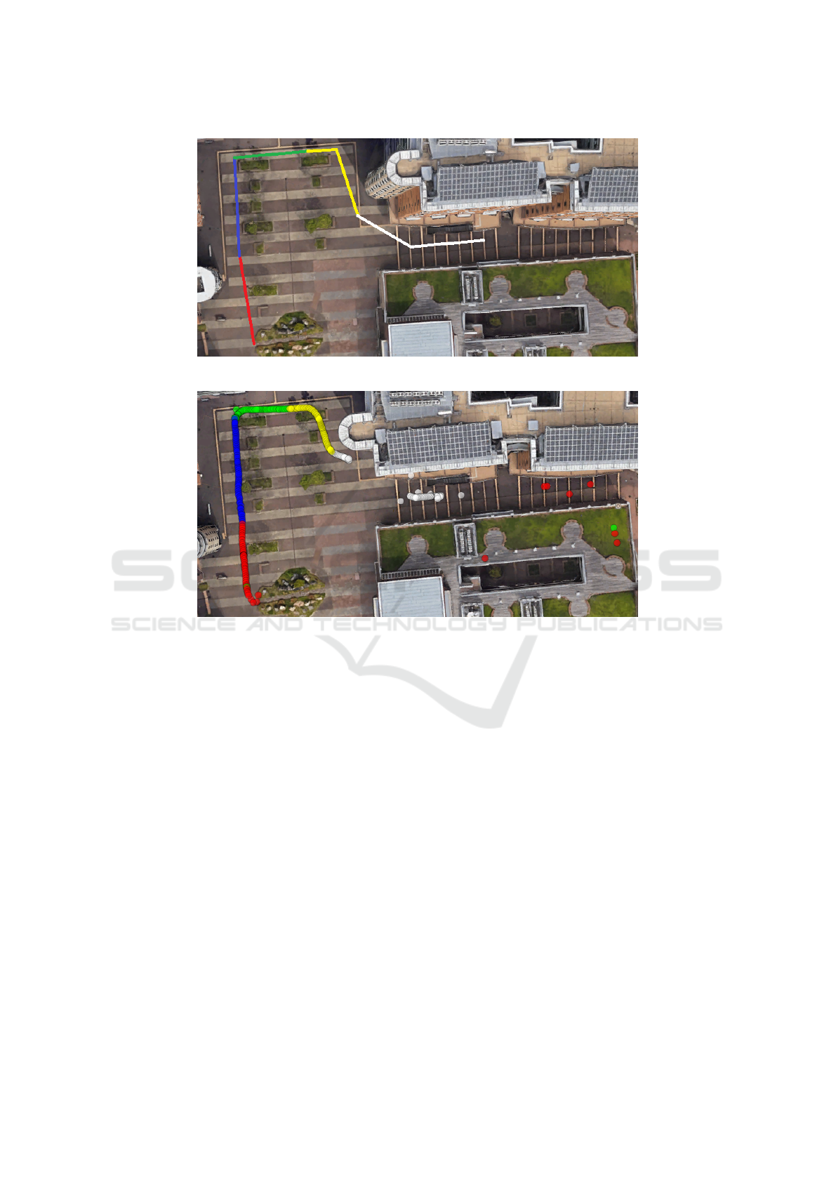
Figure 6: Result of relocalization. (a) is the path for relocalization. This include a part of Figure 5(a). (b) is the estimated
latitude and longitude visualized with Google Earth. Coded color represent the order of time-series: red, blue, green, yellow
and white. The inaccurate results such as some of red and green dots were generated when relocalization was performed
and when tracking was temporarily lost. At the area where the map database did not contain at green and yellow dots, the
trajectory was correctly estimated owing to vSLAM after relocalization.
cluded in the path for the navigation tasks, we
were not able to answer the most of the locations
correctly.
• Appearance Similarity in Building.
In our method, relocalization is based only on vi-
sual information. When there are scenes which
appearance is similar, it is not easy to correctly
relocalize. As illustrated in Figure 8, the appear-
ance at different floors was similar in the building.
Additional sensors such as magnetic field could be
useful to differentiate them.
• Scale Drift.
In monocular vSLAM, the scale drift was often
considered as a major topic. In many cases, the
drift has been occurred during rotation. How-
ever, even in the case of linear motions, there was
a tendency that the drift occurred when feature
points were not detected near the camera, and de-
tected at a distant region, illustrated in Figure 9.
This specifically occurred in the texture-less nar-
row corridors.
• Blur by Handheld Motions.
The creation of the map is carefully done to not
to generate noise. In particular, since blur will of-
ten occur, extra caution is required when turning
corners and walking at stairs. The importance of
caution in creating this map is a well-known fact
to us, but it is not so for end users operating it
as an application. In fact, when a non-specialist
used the system, the blur was so great that track-
ing became a challenging problem because it was
difficult to detect the same features at the time of
map creation.
Generating a Consistent Global Map under Intermittent Mapping Conditions for Large-scale Vision-based Navigation
791
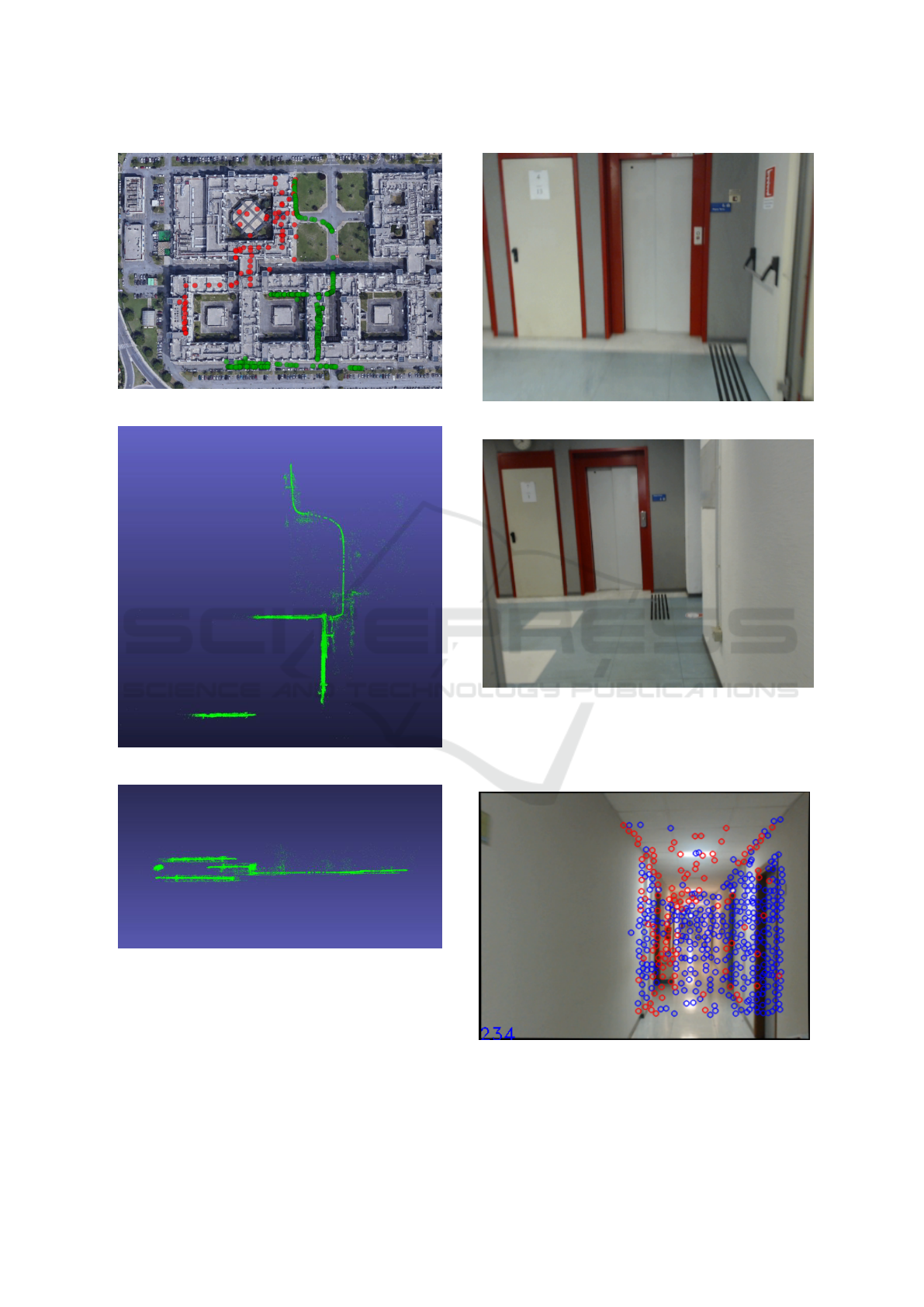
(a) Competition Venue
(b) Top view of our map
(c) Side view of our map
Figure 7: Results of our reconstruction at the competition
cite. (a) is an aerial photo of the competition venue. The
venue is approximately 170 by 200 square meter. The path
illustrated in red is the ground truth of the path used for the
competition. The path in green is where we reconstructed
in advance. (b) and (c) are top and side views of our recon-
structed map.
(a) 1st floor
(b) 2nd floor
Figure 8: Appearance similarity. (a) was captured at 1st
floor and (b) was captured at 2nd floor. Since similar fea-
tures were extracted from these scenes, it was difficult to
differentiate them based on image retrieval.
Figure 9: Scale drift. There was a tendency of the scale
drift to occur in scenes with poor front view textures and
rich distant textures.
VISAPP 2020 - 15th International Conference on Computer Vision Theory and Applications
792

The knowledge obtained by participating in the
competition mostly depended on not our map merge
technique but vSLAM techniques and their con-
straints. Therefore, it is necessary to improve the
method of vSLAM itself in future research.
7 CONCLUSION
We proposed a method for generating a consistent
global map from an intermittently created map. As
explained in the Section5, it was shown that indepen-
dent individual maps can be merged by our method,
and position estimation is possible by relocalization
to the merged maps. On the other hand, participation
in IPIN has made us aware of challenges in applying
to realistic problems. This issue is independent of the
map merge method, and is a common problem that
vSLAM has. Therefore, future studies should focus
on the vSLAM method itself.
ACKNOWLEDGEMENTS
A part of this work was supported by JSPS KAK-
ENHI, Grant Number JP18H04125.
REFERENCES
Alcantarilla, P. F. and Solutions, T. (2011). Fast ex-
plicit diffusion for accelerated features in nonlinear
scale spaces. IEEE Trans. Patt. Anal. Mach. Intell,
34(7):1281–1298.
Anguelov, D., Dulong, C., Filip, D., Frueh, C., Lafon,
S., Lyon, R., Ogale, A., Vincent, L., and Weaver, J.
(2010). Google street view: Capturing the world at
street level. Computer, 43(6):32–38.
Bian, J., Lin, W.-Y., Matsushita, Y., Yeung, S.-K., Nguyen,
T.-D., and Cheng, M.-M. (2017). Gms: Grid-based
motion statistics for fast, ultra-robust feature corre-
spondence. In Proceedings of the IEEE Conference
on Computer Vision and Pattern Recognition, pages
4181–4190.
Castle, R., Klein, G., and Murray, D. W. (2008). Video-rate
localization in multiple maps for wearable augmented
reality. In 2008 12th IEEE International Symposium
on Wearable Computers, pages 15–22. IEEE.
Corotan, A. and Irgen-Gioro, J. J. Z. (2019). An indoor
navigation robot using augmented reality. In 2019 5th
International Conference on Control, Automation and
Robotics (ICCAR), pages 111–116. IEEE.
Farrell, J. (2008). Aided navigation: GPS with high rate
sensors. McGraw-Hill, Inc.
G
´
alvez-L
´
opez, D. and Tardos, J. D. (2012). Bags of binary
words for fast place recognition in image sequences.
IEEE Transactions on Robotics, 28(5):1188–1197.
Hofmann-Wellenhof, B., Lichtenegger, H., and Wasle, E.
(2007). GNSS–global navigation satellite systems:
GPS, GLONASS, Galileo, and more. Springer Science
& Business Media.
Kendall, A., Grimes, M., and Cipolla, R. (2015). Posenet: A
convolutional network for real-time 6-dof camera re-
localization. In Proceedings of the IEEE international
conference on computer vision, pages 2938–2946.
Klein, G. and Murray, D. (2007). Parallel tracking and map-
ping for small ar workspaces. In Proceedings of the
2007 6th IEEE and ACM International Symposium on
Mixed and Augmented Reality, ISMAR ’07, pages 1–
10, Washington, DC, USA. IEEE Computer Society.
McDonald, J., Kaess, M., Cadena, C., Neira, J., and
Leonard, J. J. (2013). Real-time 6-dof multi-session
visual slam over large-scale environments. Robotics
and Autonomous Systems, 61(10):1144–1158.
Mur-Artal, R., Montiel, J. M. M., and Tardos, J. D. (2015).
Orb-slam: a versatile and accurate monocular slam
system. IEEE transactions on robotics, 31(5):1147–
1163.
Parviainen, J., Kantola, J., and Collin, J. (2008). Dif-
ferential barometry in personal navigation. In 2008
IEEE/ION Position, Location and Navigation Sympo-
sium, pages 148–152. IEEE.
Potort
`
ı, F., Park, S., Jim
´
enez Ruiz, A., Barsocchi, P.,
Girolami, M., Crivello, A., Lee, S., Lim, J., Torres-
Sospedra, J., Seco, F., et al. (2017). Comparing the
performance of indoor localization systems through
the evaal framework. Sensors, 17(10):2327.
Taketomi, T., Uchiyama, H., and Ikeda, S. (2017). Visual
slam algorithms: a survey from 2010 to 2016. IPSJ
Transactions on Computer Vision and Applications,
9(1):16.
Williams, B., Klein, G., and Reid, I. (2011). Automatic
relocalization and loop closing for real-time monocu-
lar slam. IEEE transactions on pattern analysis and
machine intelligence, 33(9):1699–1712.
Zou, D. and Tan, P. (2012). Coslam: Collaborative visual
slam in dynamic environments. IEEE transactions on
pattern analysis and machine intelligence, 35(2):354–
366.
Generating a Consistent Global Map under Intermittent Mapping Conditions for Large-scale Vision-based Navigation
793
