
Transparent Parallelization of Enrichment Operations
in Geometric Modeling
Pierre Bourquat, Hakim Belhaouari
a
, Philippe Meseure, Valentin Gauthier and Agn
`
es Arnould
University of Poitiers, CNRS, XLIM UMR 7252, 86000 Poitiers, France
Keywords:
Geometric Modeling, Parallelism, Parallel Construction of Virtual Objects, Transparently-parallel Modeling
Operation, Generalized Maps.
Abstract:
This paper presents an approach to automatically and transparently parallelize algorithms to build 2D or 3D
virtual objects in geometric modeling: In particular, we show that subdivision and Iterated Function System
constructions can be parallelized, without any explicit parallelization study by their developer. These oper-
ations are described in the framework Jerboa, where each operation is expressed as a graph transformation
and objects are topologically described using generalized maps. All transformations are handled by a generic
engine that can handle structure changes in parallel. The obtained results allow any designer of virtual environ-
ments to rely on modern multi-core and multi-processor architectures to get faster constructions of complex
objects without any skills on parallelism.
1 INTRODUCTION
Geometric modeling is usually based on a set of geo-
metric operations that modify a given 2D or 3D object
locally. During the building process, the zone where
a local operation is applied must be precisely defined.
However, some operations involve an entire ob-
ject, such as 2D or 3D refinement, volumetric extru-
sion, etc. as well as geometric operations used in It-
erated Function Systems (Hutchinson, 1981). These
constructions are often implemented as a succession
of local operations. For instance, a 2D object can be
refined by successively subdividing each of its faces.
For large and complex objects, with many elements,
this process can be quite time-consuming. For in-
stance, building fifth iteration of a Menger sponge ap-
plied on fourth iteration requires about 50 seconds us-
ing Linear Cell Complex in CGAL
1
on a i7-7820HQ
2.9GHz.
Considering modern multicore processors and
multiprocessor architectures, the application of this
process could be accelerated using parallelization. A
naive approach mainly consists in parallelizing an op-
eration by applying a local, initially sequential, al-
gorithm at several places on the object at the same
time. However, if topological consistency is wanted
a
https://orcid.org/0000-0003-4454-7756
1
https://www.cgal.org/
(finding shared vertices, edges, faces, etc.), this naive
parallel approach fails at coping with the shared fea-
tures efficiently. Indeed, they lead to concurrent ac-
cesses that heavily penalize performances due to crit-
ical sections or any other synchronous barrier intro-
duced in the parallel program. Naturally, the topol-
ogy of the object could be coped with in a ultimate
phase, but this process (where any data is potentially
shared) would lose the time benefits of the operation
parallelization in itself. The only way to avoid such
an ultimate phase is to find a numbering convention in
the structure (for vertices, edges, faces, etc.), that im-
plicitly contains adjacency relations. This numbering
convention requires a dedicated study for each opera-
tion.
In this article, we present an automatic paral-
lelization without human intervention of some geo-
metric operations in order to build complex objects.
These operations are called “enrichment operations”
because they add new elements to an object (a more
formal definition is given in the paper). These oper-
ations constitute the main steps that are required to
transform a simple object into a more complex one.
Our method guarantees to represent correct ad-
jacency relations between topological cells (vertices,
edges, faces, volumes) even if these relations are in-
trinsically shared between cells processed during a
transformation.
Moreover, parallelizing an operation usually starts
Bourquat, P., Belhaouari, H., Meseure, P., Gauthier, V. and Arnould, A.
Transparent Parallelization of Enrichment Operations in Geometric Modeling.
DOI: 10.5220/0008965701250136
In Proceedings of the 15th International Joint Conference on Computer Vision, Imaging and Computer Graphics Theory and Applications (VISIGRAPP 2020) - Volume 1: GRAPP, pages
125-136
ISBN: 978-989-758-402-2; ISSN: 2184-4321
Copyright
c
2022 by SCITEPRESS – Science and Technology Publications, Lda. All rights reserved
125

from its sequential version and, as a subsequent step,
consists in making it parallel. On the contrary, our
approach aims at automatically parallelizing a given
operation, without any intervention of its developer
by precisely analyzing topology.
To meet this goal, we choose to rely on Jerboa,
a freely-available modeling platform
2
. This tool pro-
vides us with an adapted framework, mainly consist-
ing of a rule-based language for graph transforma-
tions that provides any transformation rule with static
and dynamic checks. Jerboa is based on different
engines that handle these rules to carry out geomet-
ric operations (Belhaouari et al., 2014). We found
that these engines were well-suited to parallelism and
could be enhanced and optimized in time for some
global geometric transformations. More precisely, we
propose an adapted rule engine that gives, automati-
cally, a parallel implementation of geometric transfor-
mations based on parallel graph manipulations.
The paper is therefore organized as follows: After
the presentation of related work in section 2, Jerboa is
detailed in section 3. Our new parallel engine is then
presented in section 4. Performance of this engine
is detailed in section 5 followed by conclusion and
future work.
2 RELATED WORK
Few geometric modeling algorithms have benefited
from concurrent programming. Indeed, they are usu-
ally applied on a local area of an object and handle
few vertices, edges, etc. However, some modeling
operations deal with a consequent part or the totality
of an object and can be accelerated using paralleliza-
tion if the object to build is complex. This mainly
concerns global mesh processing methods (Coupez
et al., 2000) and, among these, subdivision algo-
rithms. However, the parallelization is usually ded-
icated to a given subdivision method, for instance the
Butterfly approach in (Padr
´
on et al., 2002). A re-
cent method has tried to gather several subdivision
schemes into a unique algebra (Mlakar et al., 2019).
This approach is efficient by focusing on the compu-
tation of new vertex positions but is dedicated to sub-
division schemes only.
Some approaches only aim at producing on-the-fly
refinement in parallel but not with the intent to store
the final mesh (Nießner et al., 2012). On the contrary,
other approaches deal with the complexity of the final
mesh by distributing the memory requirements and
manipulation between processing units. Theses ap-
2
https://xlim-sic.labo.univ-poitiers.fr/jerboa
proaches need to separate the manipulated mesh into
clusters. This allows for the use of sequential algo-
rithms inside a cluster but the management of clus-
ter borders needs data exchanges between processing
units (Damiand et al., 2018). Strategies have been
proposed to limit these exchanges for specific sub-
division schemes (Gargallo-Peir
´
o et al., 2017). The
partitioning of the manipulated mesh into clusters can
lead to load balancing problem and a fine-grained ap-
proach can be interesting (Chen et al., 2013).
More generally, geometric algorithms are also
used during construction in procedural modeling as
well as in Iterated Function Systems (IFS) (Hutchin-
son, 1981). Procedural modeling can benefit from
parallelization, but existing methods are usually re-
stricted to linear structures (Lipp et al., 2010) and not
surface or volumetric structured meshes.
Our goal is to allow for the building of topologi-
cally consistent complex objects using parallelization
to speed-up construction. Our method can also be
seen as a parallelized approach to build IFS, for non-
linear structures, on modern platforms by relying on
the multicore and multiprocessor architectures.
We consider that the main contributions of our
method are: (1) the generation of complex, quasi-
manifold surface or volumetric objects, with a notice-
able speed-up, (2) the automatic and transparent par-
allelization of any building process based on enrich-
ment operations using a fined-grained approach, (3)
the guaranty that the adjacency relations are correctly
computed and updated during a building process.
Our parallelization approach has been made possi-
ble due to the specific properties of Jerboa, that is, the
inner structure to represent topology and the way ge-
ometric transformations are handled. More precisely,
parallelization is made possible thanks to Jerboa’s
rule syntax. As a consequence, our approach heav-
ily depends on its strategy to cope with geometric, and
more exactly topological transformations. This means
that our method cannot be applied directly on classi-
cal geometric modeling API, since transformation are
not handled the same way as in Jerboa (using a for-
mal approach that mainly copies, pastes and modifies
graph patterns). The next section is thus dedicated to
the presentation of this tool.
3 GENERAL PRESENTATION OF
Jerboa
Jerboa is a rapid prototyping platform dedicated to
topology-based geometric modeling. It allows a de-
signer to quickly specify one or more geometric oper-
ations on 2D or 3D models. It heavily relies on graph
GRAPP 2020 - 15th International Conference on Computer Graphics Theory and Applications
126

transformations theory and uses a dedicated graphic
language to design transformation rules via an edi-
tor. Not much code has to be written to create an
operation, since only the way to handle and update
any information embedded in the model (such as new
position of vertices) after a transformation must be
given. The runtime execution of an operation is done
using an engine that interprets a called rule and ap-
plies changes on a selected object. To understand
how Jerboa can be a valuable tool to parallelize ge-
ometric operations, it is mandatory to understand the
inner structure and the language used by transforma-
tion rules. These features are thoroughly described in
(Belhaouari et al., 2014), but, in this section, we recall
elements that help understanding how parallelization
can be applied.
3.1 Inner Topological Structure
The inner structure of Jerboa relies on a generalized
combinatorial map (G-map). This structure is in-
spired from half-edges (Campagna et al., 1998) but
is generalized for any dimension, and allows for the
representation of non-oriented manifolds (Lienhardt,
1994). Thus, a G-map may be represented as an un-
oriented graph, where nodes are basic elements called
darts and arcs
3
are labeled by dimension (called α
d
for a relation associated with dimension d). Indeed,
arcs always aim at linking two entities of a given di-
mension explicitly known by the value of their label.
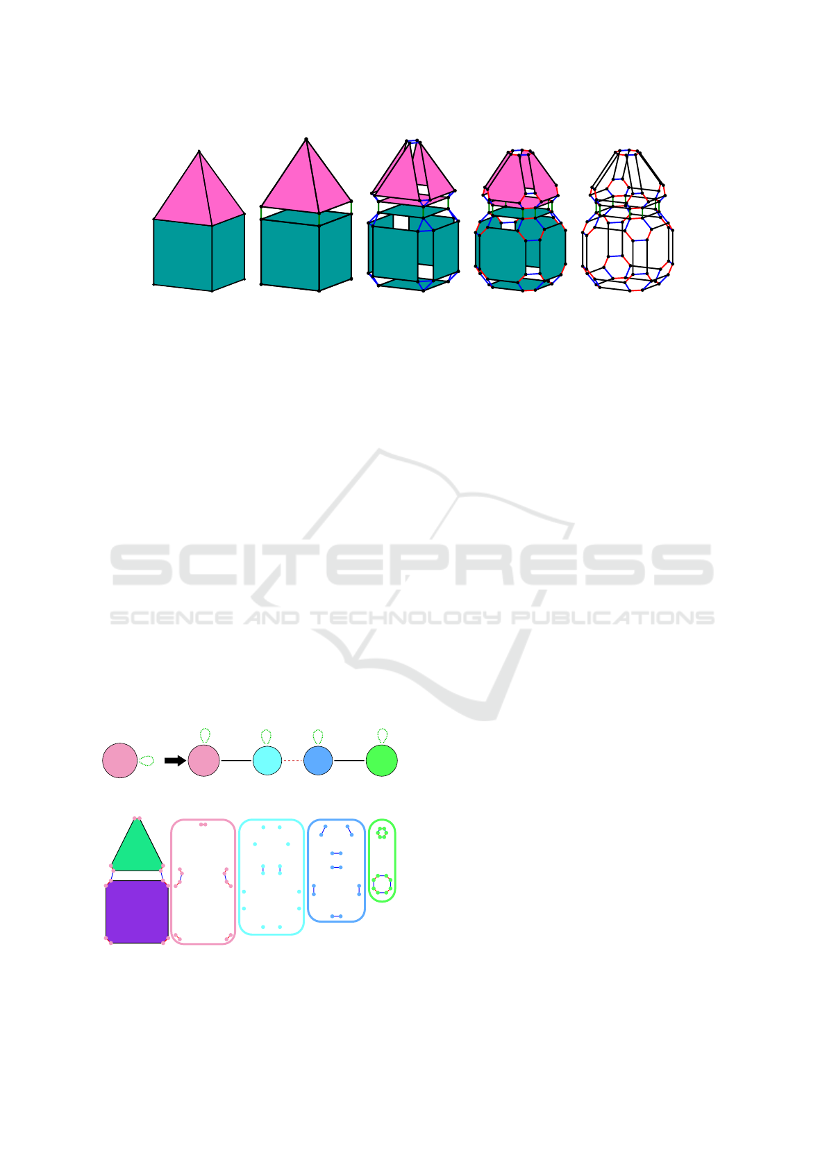
Figure 1 presents the decomposition of a 3D com-
plex object along decreasing dimensions. Two vol-
umes are linked along a “dimension 3” relation (α
3
)
(Fig. 1a). Then, one volume is decomposed into faces
linked by a “dimension 2” relation (α
2
) (Fig. 1b).
Successive edges on a face are linked by a “dimen-
sion 1” relation (α
1
) (Fig. 1c). Finally, one edge is
composed of two darts linked by a “dimension 0” re-
lation (α
0
) (Fig. 1d). The topology of the initial object
is described in Figure 1e where all geometrical infor-
mation (embeddings) has been deleted.
Some constraints must be verified to ensure the
consistency of a G-map. Typically, each dart must be
connected to other darts with one and only one rela-
tion of each dimension, from 0 to n where n is the
dimension of the object to which it belongs to. Con-
cerning dangling condition, a dart must be linked to
another dart or to itself. If a dart is linked by α
i
to
itself, it is said to be α
i
-free. On Figure 1e, some
darts do not have α
3
links (these links are not repre-
sented): They correspond to faces with no adjacent
3
Dedicated jargon to avoid ambiguity between “edge”
from graph theory and “edge” from geometry, i.e. segment
between two vertices. Our “arcs” are not oriented.
volume. Another constraint deals with the so called
“manifold condition”. Following α
i
and then α
j
or
α
j
and then α
i
from a starting dart must lead to the
same dart, when i + 2 ≤ j. All these conditions are
verified within Jerboa environment, most of them in
a static way at design stage, so that no inconsistent
structure can be generated.
With this formalism, topological cells (vertices,
edges, etc.) are defined as a subgraph with a particular
set of relations, defined as their labels. For instance,
from a given dart d, in 3D, the subgraph hα
0
,α
2
,α
3
i
(d) denotes the edge including d. hα
1
,α
2
,α
3
i (d) de-
notes the vertex that includes d. hα
0
,α
1
,α
2
i (d) de-
notes the incident volume. hα
0
,α
1
,α
2
,α
3
i (d) stands
for the whole connected component to which d be-
longs and so on. In addition, G-maps support supple-
mentary subgraphs, that are called orbits that are not
necessarily topological cells, and we call “orbit type”
the list of links to follow to get all the darts of an or-
bit. For instance, it is possible to use the corner of
a face with the orbit type hα
1
i or make a difference
between a 2D edge (orbit type hα
0
,α
2
i ) between two
faces (possibly belonging to the same volume) and a
3D edge (orbit type hα
0
,α
2
,α
3
i ) shared by several
volumes.
This feature is heavily used to formalize embed-
dings. In Jerboa, when additional data must be em-
bedded in a G-map, an orbit type must be associated
with each data for Jerboa to be able to check consis-
tency after topological changes. Every orbit of a type
associated with a given data should embed a value.
Thus, since Jerboa ensures this property, it detects
where a developer of an operation forgets to add a
computation of a value for a new orbit that appears
after a transformation when this orbit type should em-
bed a data. Jerboa also ensures that every dart of an
orbit that embeds a data share the same value.
3.2 Definition of an Operation
In Jerboa, graph transformations are used to modify a
G-map. This approach comes originally from formal
methods and allows Jerboa to preserve consistency di-
rectly from the description of an operation. This sec-
tion is dedicated to the graphical language that a de-
veloper uses to describe an operation, in the form of
a transformation rule. The following section presents
how rules are interpreted and executed by a unique
engine. Rules are divided into two parts: the left hand
side which indicates the pattern where the operation
should be applied and the right hand side which ex-
plains transformations from the left pattern.
Figure 2a illustrates the well-known Catmull-
Clark subdivision operation in Jerboa (Catmull and
Transparent Parallelization of Enrichment Operations in Geometric Modeling
127
(a) Volume
decomposition
(b) Face decompo-
sition
(c) Edge decom-
position
(d) Vertex decom-
position
(e) Final topology
Figure 1: Object decomposition into a G-map. α
3
are represented in green, α
2
in blue whereas α
1
are red. α
0
are black.
Clark, 1978). The left pattern has a unique node
which is labeled with an orbit to represent a specific
element. Here, the orbit type hα
0
,α
1
,α
2
i is shown,
that means that the subdivision must be applied on a
set of connected faces (that can be a unique volume if
the surface is closed). A looping arc labeled α
3
indi-
cates that this set of faces must be free along dimen-
sion 3, that is to say: No face of the set is connected
to a volume. Obviously we could make a more gen-
eral operation that subdivides any face of several con-
nected volumes, but it would make the example more
complex and we want to keep it as simple as possi-
ble by not coping with α
3
links. The right hand side
has four nodes and topological relations. The most
left node represents the original set of faces where
edges have been deleted (α
0
removed) so that another
node can connect to this one. The two center nodes
represent a new geometric vertex at the midpoint of
each edge of the initial object. More precisely, these
nodes represent face corners, due to the α
1
link be-
tween them. The most right node contributes to the
new vertex positioned at the center of each initial face.
<α0, α1, α2>
α3
n0
<α2, _, _>
position
n2
<_, _, α2>
position
n1
<_, α1, α2>
n0
<α2, α1, _>
position
n3
α1 α0α0
α3 α3
α3 α3
(a) Rule representation
(b) Node
identification
(c) Node duplication
Figure 2: Catmull-clark subdivision operation in Jerboa.
The application of such a rule is heavily based on
a folding mechanism (Ehrig et al., 2006) on each dart
of the initial object. To better understand this mech-
anism, let us apply it to a simple quad linked by one
of its edge to a triangle. Bottom of Figure 2 shows
a first step of the construction. First, the node of the
left part of the rule is identified with all the darts of
the object where the operation is applied, that is, in
our example, the eight darts of the quad and the six
darts of the triangle (Fig. 2b). This node is kept (n0)
and duplicated three times (n1, n2 and n3) in the right
part of the rule. In practice, this means that three new
groups of fourteen darts are created (represented, in
Figure 2c, with a color code corresponding to a node
of the rule). Some relations are automatically created
between these darts, by renaming (changing the di-
mension of) already-existing relations in the original
node. These are called “implicit” links and are writ-
ten inside each node. For instance, when duplicating
the initial left node to create node called n3, all α
0
links from the initial quad are kept but renamed into
α
2
to link the newly-created darts. α
1
links are kept
as in the initial quad. α
2
links are discarded. The ini-
tial node can also be modified, here α
0
are deleted, as
previously mentioned.
Explicit links (corresponding to an arc in a rule)
are then built between the new darts to complete the
construction, as this can be seen in Figure 3b (with the
same color code than in Fig. 2a). For instance, a dart
in node n1 created as a duplication of a dart in node
n0 is linked to this dart with an α
0
link, as stated in the
operation of Figure 2a. Figure 3c illustrates the fold-
ing mechanism where Jerboa rule can be recognized
for each of the 14 darts of the original node. Note
that all links, for all dimensions, are handled by the
rule for every node, so for all the darts they include
(newly-created or modified). If not, such a rule would
be considered as inconsistent (which is verified at the
design of the rule) and could not be applied.
The rule in Figure 2a also points out that the posi-
GRAPP 2020 - 15th International Conference on Computer Graphics Theory and Applications
128
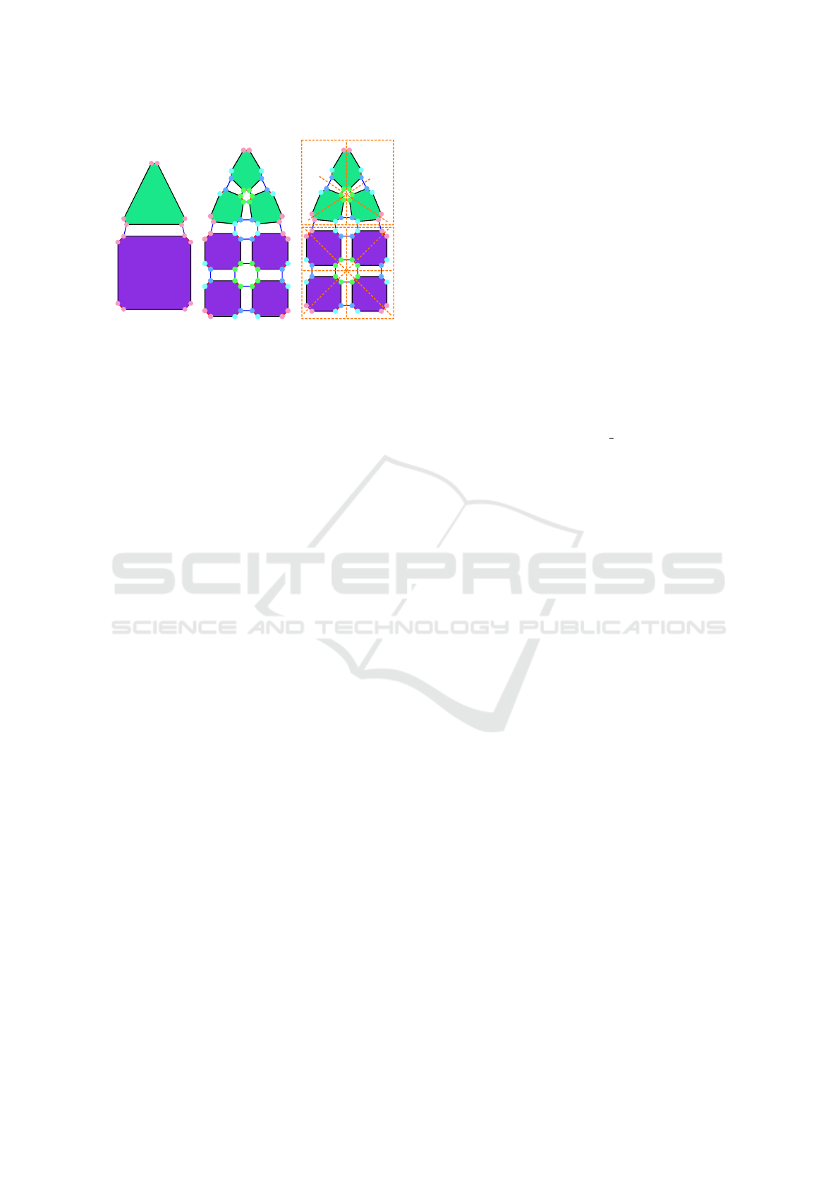
1
2
0
3
4
13
5
6
7
8
9
10
12
11
(a) Initial (b) Final object (c) Folding mech-
anism
Figure 3: Result of the application of Jerboa Catmull-Clark
rule and focus on the application of this transformation rule
on each of the 14 darts of the initial mesh (in pink).
tion of the vertices inserted in the midpoint of edges
and faces must be computed, whereas positions of ini-
tial vertices do not change (smoothing is ignored in
this example).
It must be emphasized that Jerboa does not carry
out an operation like other geometric modeling en-
vironments. Indeed, Catmull-Clark is usually imple-
mented by first introducing a midpoint on each edge,
creating a vertex at the midpoint of each initial face
before erasing this latter, creating adjacent edges for
every midpoint vertex and creating new faces based
on subdivided and newly created edges. On the con-
trary, Jerboa rather consider an operation in terms of
node identification, duplication, label renaming for
arcs, etc. Jerboa always relies on the same process,
whatever the desired operation written in its graphic
language. This process is handled by a generic, that
is “operation-independent”, engine that is described
in the following section and allows for a completely
transparent parallelization of any operation.
3.3 Jerboa Engine
The formalism presented in previous section offers a
significant advantage: A unique algorithm, so called
“Jerboa Engine” handles any Jerboa rule describing
an operation. This section describes the main steps of
this engine, but focuses on the steps used by enrich-
ment operations and ignores the steps only required
by other kinds of operation (even if they are effec-
tively handled by Jerboa’s general purpose engine).
The first step is the identification of the left pattern
of an executed rule. More precisely, this step aims at
mapping the left, symbolic, node with a set of all darts
belonging to the orbit type written inside this node.
This step also checks folding properties around orbits.
In our example, it identifies the full set of connected
faces (or the unique volume) given as parameter to the
operation.
The second step consists in checking developer
preconditions with the found left pattern. It allows,
for instance, a user to check embedding values after
the engine checks topology aspect.
The third step is a complex step where the right
pattern of the applies rule is intensively employed to
cope only with topological aspects. First, the engine
creates, for each node in the right pattern, as many
new darts as darts identified during the first step. For
instance in the Catmull-Clark operation, it creates for
each existing dart of the identified node, three new
darts (identified by node n1, n2 and n3). Then, the en-
gine rewrites topology information, that is create links
for each dart, in accordance with the operation. It pro-
ceeds in two steps. First, it handles implicit arcs. Each
label inside nodes of the right pattern is analyzed. If
a link type is not marked as ’ ’ in a node’s label, it
is reproduced between the set of darts associated to
the considered node according to the links between
darts identified with the left pattern. Each link can be
renamed before it is reproduced, that is, it is possi-
ble to change the dimension of the link. Second, the
engine analyzes explicit arcs between any two con-
nected nodes in the right pattern to link each dart as-
sociated to one of these nodes to its related neighbor
dart on the other node.
The fourth step is dedicated to embedding values.
For every embedding of the object, the engine must
take an inventory of all orbits of its associated type
to handle embedding values for each of them. The
engine makes a difference between values that have
to be computed and already-existing values, defined
on initial orbits and that only need to be spread when
these orbits are modified. For computed values, the
designer has to provide a computing code (in a dedi-
cated language).
4 PARALLEL
TRANSFORMATION ENGINE
The generic algorithm to handle operations shown in
previous section gives the opportunity to design a par-
allel process of any construction operation. First, we
have to analyze the different stages of Jerboa Engine
to find potential parallelization issues and deadlocks.
4.1 Jerboa Engine Analysis
The steps of the Jerboa Engine seem simple at first
sight, but they hide many difficulties and implemen-
tation issues. The most significant difficulties appear
Transparent Parallelization of Enrichment Operations in Geometric Modeling
129

during embedding evaluation and refer to orbit ma-
nipulation.
The engine computes embedding values in the ini-
tial object space because, this way, computations may
reuse values already present in this object, such as or-
bits, neighbor darts or initial embedding values. How-
ever, the engine must determine where computations
must be called, so it also manipulates the final object
to determine every orbit of any orbit type that em-
beds information. A similar problem appears when
an already-existent embedding value, associated with
a given orbit type, must be spread from an initial dart
to newly-created darts belonging to the same orbit.
The engine handles this issue by determining every
orbit (of a given type, the one associated to a given
embedding), that is, partitioning the set of darts into
equivalence classes of darts belonging to the same or-
bit, and distribute an embedding value to all the darts
constituting it.
All these issues lead us to classify operations with
respect to their topological properties. Currently, we
identify three classes: update operations that do not
induce topology changes but only imply modification
of embedding values, enrichment operations which
have only one node as left pattern and increase the
number of darts without deletion, and other opera-
tions. This article focuses on enrichment operations,
since they are used to make an object more com-
plex (subdivision, triangulation, extrusion, etc.), and
both update and enrichment operations can benefit
from the same optimization approach. On the con-
trary, considering the last class of operations, where
deletions might be required, consequent treatments to
satisfy consistency of topology and embedded values
must be used and heavily complicate parallelization.
Moreover, update and enrichment operations generate
less concurrent access issues contrary to other kinds
of rules and are more likely to benefit from paral-
lelism. We decided to let this third class of rules as
future work.
Now, let us consider the different steps of Jerboa
Engine (see section 3.3). In enrichment operations,
the left pattern is reduced to one node identified with
one orbit type that defines the zone where the enrich-
ment operation is applied.
The second step resorts to user code (to manage
embedding values), so a dedicated automatic code
analysis is required to parallelize this step. This is not
our purpose, so we let these steps sequential and use
them as barriers to synchronize other steps. The third
step, that is the one that interprets the right part of the
rule, offers several parallelization opportunities.
4.2 Parallelized Engine for Enrichment
Operations
At first, the engine checks if the rule given as input
is compatible with parallelism, that is, if it is an up-
date or an enrichment rule: (1) There is a unique node
in the left pattern of the rule, (2) this unique node
must have a full label orbit (no symbol bottom ’ ’ can
be used), (3) the left node is preserved on the right
pattern (then no deletion occurs). Our approach also
assumes that computation of embedding values are
concurrent-safe.
Note that, to ensure consistency constraints of en-
richment operations, the orbit associated with the left
node usually corresponds to a complete connected
component, in enrichment operations.
4.2.1 Parallelizing Topological Transformations
When the engine starts the application of an opera-
tion, it determines, first, all darts which represent the
unique node of the left pattern by walking through
the orbit shown in its label. With this list of darts
(called left darts), our engine computes an indexed
structure to organize topological transformations ef-
ficiently. Contrary to Jerboa orginal data structures,
such an indexed, local, structure is common and it al-
lows for the use of parallel patterns (McCool et al.,
2012). It appears as a matrix that gives, for all in-
dexed darts, the index of the darts that are 0-linked
with them in a first line, those that are 1-linked in a
second line, and so on for every link. This matrix is
first used to represent the initial structure, as can be
seen in Table 1. Its size is the number of left darts
and is called “left adjacency matrix”. It is filled in the
first step of the algorithm, during the gathering of all
left darts. A similar structure is also allocated to rep-
resent the transformed structure, and is called “right
adjacency matrix”. Since left darts are duplicated for
each node in the right pattern, the size of this right ma-
trix is the product of the number of left darts and the
number of nodes in the right pattern. These matrices
must ensure non-orientation constraints: If a dart d is
linked to a dart e for a given dimension, then it must
be ensured that e is linked to d for the same dimen-
sion. The following algorithms guarantee this prop-
erty. Note that, concerning update operations, left and
right matrices are the same.
Table 1: Left matrix of object in Figure 3a.
ID 0 1 2 3 4 5 6 7 8 9 10 11 12 13
α
0
1 0 11 10 5 4 7 6 9 8 3 2 13 12
α
1
13 2 1 4 3 6 5 8 7 10 9 12 11 0
α
2
0 1 3 2 4 5 6 7 8 9 11 10 12 13
GRAPP 2020 - 15th International Conference on Computer Graphics Theory and Applications
130

The index of each dart is determined this way: If
l is the number of left darts, the darts of the right pre-
served node are numbered from 0 to l −1, as the same
index stands for darts of the left pattern (index used in
the left matrix) and their image in the preserved node
(index used in the right matrix). Darts created for the
first new node in the right pattern are numbered l to
2l − 1, and so on. More generally, if an initial dart k
is duplicated in right node h, the index of the copy is
h × l + k (h = 0 corresponds to the preserved node).
At this point, no more search or walk-through are car-
ried out outside of this range of darts since any node
used by the operation is indexed and corresponds to
an entry in the structure.
The computation of topology consists in filling the
different lines of the right matrix, by first coping with
implicit links and then with explicit ones.
Concerning implicit links, for a given right node,
our engine inspects the word of its orbit label. Each
word means a mapping of links of a given dimension
i to all the links of a possible other dimension j in the
initial structure (renaming mechanism). Our method
just copies the line j of the left matrix into the line
i in the right matrix at indices corresponding to the
concerned node. An offset of h × l is applied to find
destination columns but must also be applied on each
copied value, since the darts concerned by these im-
plicit links are not indexed from 0 to l − 1 but from
h × l to (h + 1) × l − 1 if h is the current processed
node. Parallelism is carried out over each word in the
orbit label of each right node and for each copied link.
Concerning explicit arcs, parallelism is handled
over each explicit arc present in the rule and each left
darts. Remember that an explicit arc of dimension e
between two nodes a and b binds any dart n
a
in a to its
corresponding dart n
b
in b. Corresponding dart means
that n
a
and n
b
come from the same left dart k. Hence,
we have n
a
= a × l + k and n
b
= b × l + k. It is there-
fore possible to directly fill, in parallel, the line e for
columns n
a
and n
b
for each k between 0 and l − 1.
4.2.2 Parallelizing Embeddings Management
The next stage handles embeddings. This step in-
cludes two parts: determination of where the compu-
tation must be called in the final topology and effec-
tive computation in the initial topology. This duality
is solved easily since the right matrix presented in pre-
vious section represents the modified object whereas
the left matrix and the current G-map of the object
still represent the initial state. Here again, parallelism
is possible for both aspects.
The determination of where the computation must
occur consists in finding a unique representative dart
for each orbit of a given type in order to avoid re-
dundant computation of the same value among darts
of the same orbit. We propose the so-called “islet al-
gorithm” that computes representative darts of all or-
bits of the same type simultaneously. This algorithm
takes a set of darts and an orbit type as input, and it
gives as output, for each dart, the representative dart
of the orbit to which it belongs for the specified orbit
type and a list of the representative darts, and conse-
quently, the list of orbits. The algorithm consists in
tightening incrementally each α
i
link, where α
i
be-
longs to the selected orbit type. The PRAM complex-
ity is O(m) where m is the size of the biggest orbit of
the zone concerned with the embedding to compute
or propagate.
input : T: list of indices of darts
o: an orbit type
output: TR: array of the representative dart of
the orbit type o for each dart in T
TF: array of darts included in TR
giving one dart per orbit.
// Initialization
foreach id ∈T do in parallel
TR[id] ← id ;
end
// Contraction over o
f inish ← False ;
while not f inish do
f inish ← True ;
foreach α
j
∈ o do
foreach id ∈T do in parallel
next ←α
j
(id) ;
// α
j
() found in the right
adjacency matrix
if TR[next] <TR[id] then
TR[id] ←TR[next] ;
f inish ← False ;
end
end
end
end
// Sort and compact pattern
TF← { TR[i] such that TR[i] = i } ;
Algorithm 1: Islet algorithm.
Algorithm 1 details the different steps. First, two
shared structures are initialized: TR that stores the rep-
resentative dart selected by each dart in its orbit for
the selected orbit type and TF a list of representative
darts (initially empty). Each dart selects itself as the
representative dart of its orbit, so TR[i] ← i. Then, a
loop starts. Each step deals with all the α
i
links from
the input orbit type. The algorithm spreads the repre-
sentative dart with the minimal index along each α
i
.
Transparent Parallelization of Enrichment Operations in Geometric Modeling
131

α0
α1
α1
α0
α1
α0 α0
α2 α2
0
1
2
3
4
5
6
7
(a)
α0
α1
α1
α0
α1
α0 α0
α2 α2
0
1
2
3
4
5
6
7
(b)
α0
α1
α1
α0
α1
α0 α0
α2 α2
0
1
2
3
4
5
6
7
(c)
α0
α1
α1
α0
α1
α0 α0
α2 α2
0
1
2
3
4
5
6
7
(d)
Figure 4: Execution of the Islet algorithm for orbit type
hα
0
,α
1
i .
In practice, for each dart d and its neighbor e linked
by α
i
, the algorithm selects the dart with the minimal
index among their representative darts TR[d] and TR[e]
and update the value of the greater one. This loop is
iterated until no contraction occurs after trying each
link α
i
of the selected orbit type. Finally, a classic
compact pattern removes redundancy in TR to keep
only one dart per orbit in TF.
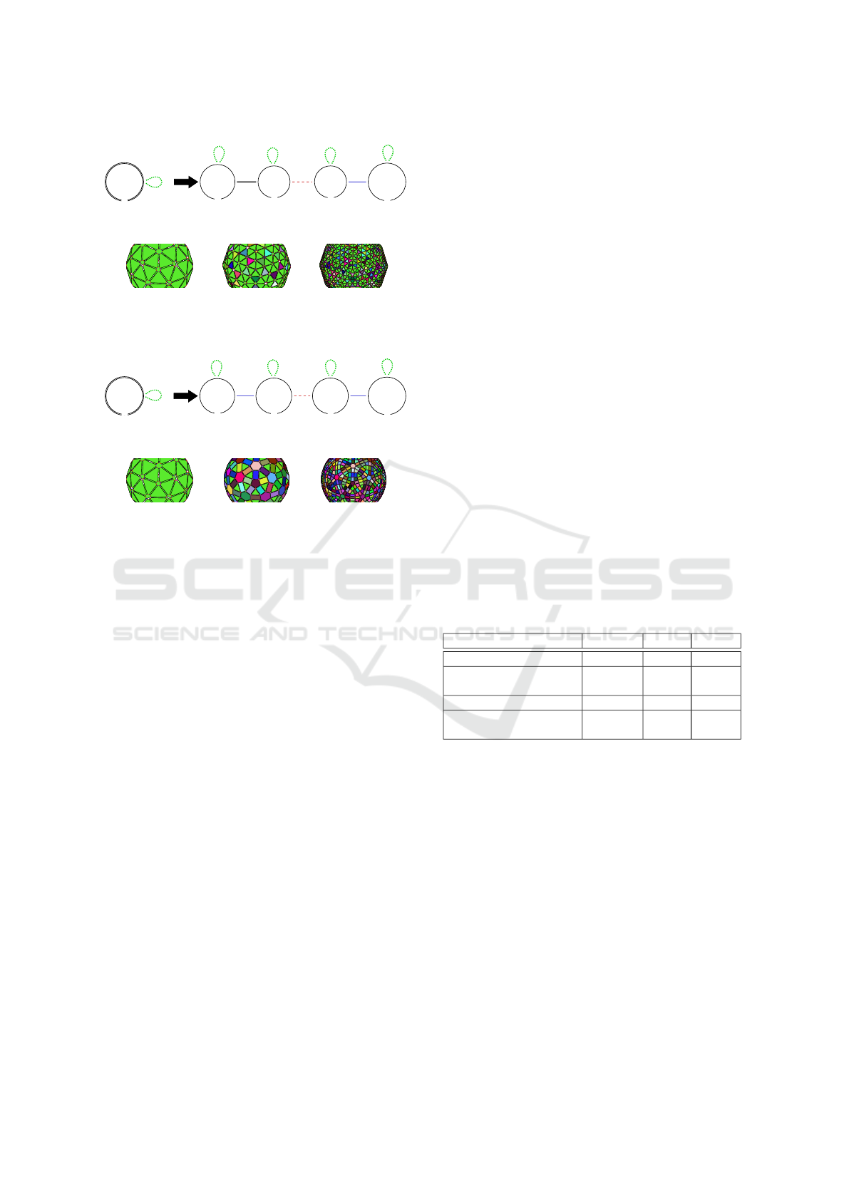
Figure 4 shows an execution of this algorithm on
an object to find all representative darts for orbit type
hα
0
,α
1
i (face orbit). The label inside each dart (cir-
cle) always gives its index. A color is associated with
each index and, along the algorithm, shows which
representative dart is selected by each dart. Initially,
no contraction has been applied and each dart selects
itself as its representative dart for the orbit. This is
why, in Figure 4a, each dart has a different color (dart
0 is red, 1 is blue, and so on). The algorithm contracts
alternatively α0 and α1 in order to spread representa-
tive darts. Figure 4b shows the result after a contrac-
tion over α0. Here, dart 5 takes the color of dart 0
because they are linked by α
0
and the index of dart 0
is lower than dart 5. For the same reason, dart 6 takes
the color of dart 4, and so on. Figure 4c displays the
next contraction over α1. Now, darts 3 and 4 also se-
lect dart 0 respectively from dart 5 and dart 0. At this
point, the algorithm has determined that darts 0, 3, 4
and 5 belong to the same face orbit. Figure 4d shows
the final result where dart 0 has been elected by all
the darts of the above face. Dart 2 has been elected
for the below face. No more contraction occurs, the
algorithm stops. The object is composed of two faces
(the red and the pink ones).
Once Islet algorithm has built TR and TF, TF is first
used to compute the values for the embedding value
associated to each orbit. TR is then used to spread
this value so that all the darts of an orbit share the
same embedding value. Finally, all the topological
modifications computed in the local adjacency matrix
are copied (in parallel) to update the global G-map.
5 RESULTS
This section presents different applications and time
performance for different operations. It must be em-
phasized that these results rely on strictly the same
parallel Jerboa engine, which handles a dedicated rule
for each example presented in this section. The en-
gine is compiled once for any rules independently on
operation and it could be used for any other enrich-
ment operation that is expressed in Jerboa formalism.
The proposed examples aim at showing the versatil-
ity of our approach. We first study several subdivi-
sion operations for surface meshes, and then show
an example of a 3D IFS. For each case, Jerboa rules
are shown. Since Jerboa has been first developed in
Java, our parallel engine has also been implemented
in this language, in order to validate the approach for
parallelization. Our measures have been carried out
on a general purpose machine, with a processor i7-
7820HQ 2.9GHz with 8 (hyperthreaded) cores, 32GB
of RAM and JDK 11.
5.1 Subdivision Surfaces
Subdivision surfaces offer good examples to present
our transparent parallelism. There are different
classes of subdivision schemes depending on subdi-
vided elements and face kinds (triangular or quad).
We can cite those that split faces into sub-faces
and those that split vertices into multiple vertices.
The Loop (Loop, 2002) and Catmull-Clark (Catmull
and Clark, 1978) subdivisions divide faces into sub-
faces. The former is dedicated to triangular meshes
and the latter to quad meshes. We have also im-
plemented Doo-Sabin subdivision (Doo and Sabin,
1978). This one splits vertices of faces instead of
face directly. Figures 2a, 5a and 6a present imple-
mentation of such operations in Jerboa. The two first
selected subdivisions produce regular patterns: Us-
ing Loop’s approach, triangles are subdivided into
four sub-triangles (Figs. 5b-5d) and in Catmull-Clark,
quads become four sub-quads (Fig. 3b). On the
contrary, Doo-Sabin subdivision depends on adjacent
faces around vertices (Figs. 6b-6d). By the way, it can
be remarked that the right pattern of these operations
include four nodes, but with different relations linking
them. Thus, the role of each node depends on the op-
eration: For instance, nodes n1, n2 and n3 in Loop’s
rule (Fig. 5a) represent a same vertex. In Doo-Sabin’s
rule (Fig. 6a), all nodes represent the same vertex
which is expected since this scheme works solely on
vertices.
Figure 7 shows time execution of each subidivi-
sion with respect to the number of iterations of vari-
GRAPP 2020 - 15th International Conference on Computer Graphics Theory and Applications
132
<α0, α1, α2>
n0
α3
<α1, α0, _>
color
position
n3
<_, α0, _>
position
n2
<_, α1, α2>
n0
<_, _, α2>
position
n1
α0
α3
α3
α1 α2
α3 α3
(a) Jerboa rule
(b) (c) (d)
Figure 5: Loop subdivision rule and some applications.
<α0, α1, α2>
n0
α3
<α0, _, _>
color
position
n1
<_, _, α0>
position
color
n2
<_, α1, α0>
color
position
n3
<α0, α1, _>
position
n0
α1α2
α3
α2
α3
α3
α3
(a) Jerboa rule
(b) (c) (d)
Figure 6: Doo-Sabin subdivision rule and some applica-
tions.
ous tools/libraries.
We choose open source libraries such as Open-
SubDiv (Polson, 2013) which offers various types of
execution, MeshLab (Cignoni et al., 2008) a well-
known tool of the community, OpenFlipper (M
¨
obius
and Kobbelt, 2012) a GUI of OpenMesh, a topology-
based modeler, and CGAL with polyhedron (The
CGAL Project, 2019) and linear cell complexes
(LCC) (Damiand and Teillaud, 2014) that are based
on combinatorial maps. All these tools/libraries are
developed in C++ in a classic way, with much ded-
icated optimization, carefully studied by their devel-
opers and specialized in the targeted operation. Since
we propose an automatic and general parallelization,
the same for any enrichment operation, it clearly can
not offer the same performance. Moreover, our results
are also harmed by Java, the implementation language
chosen by Jerboa, and, more precisely, by (recently-
implemented) Java Streams and Java Garbage Collec-
tor that attempts to free memory when many darts are
allocated (note that all experiments exceed millions of
darts, it peaks about 30 million darts on Loop exper-
iment). However, our parallel engine gives better re-
sults than Jerboa sequential default engine after some
iterations when overhead time fades into data charge.
Concretely, at the end of the experiment, the paral-
lel engine is from two to three times faster than the
default one.
This experiment shows many elements that inter-
fere with results.First, the overhead time generated by
parallelism may influence performance badly: As an
example, OpenSubDiv (which obtains the best results
of this experiment) has better result with a sequential
computation (about 10 ms) than parallel one (about
13 ms). Second, dedicated optimization of the code
influences drastically performance: CGAL LCC has
good performance for Loop operation whereas per-
formance for Catmull-Clark is catastrophic after the
fourth iteration: It seems that this operation has been
less optimized. This last remark speaks in favour of
our transparent parallelism approach where a unique
engine is developed for all operations instead of giv-
ing the same parallelization effort for each kind of op-
eration. To strengthen this last argument, we notice
that some tools offer the ability to apply multiple iter-
ations in a single step or one after the other (as Jerboa
does). This functionality provided by some tools im-
plies, here again, dedicated, specifically-studied, op-
timization to benefit from parallelism. For instance,
OpenFlipper obtains 8 Loop subdivision at once in
4061.285 ms and one by one 7089.825 ms. The same
is observed for MeshLab where iterations in one step
take 226 ms and the application of several iterations
555 ms, thus a clear difference indicates a global op-
timization in this treatment.
Table 2: Detailed execution time of the 8th iteration with
our parallel engine.
Steps Doo-Sabin Loop Catmull
Left pattern identification 17.30% 18.89% 14.06%
Matrix building and topology
update
7.84% 8.71% 6.8%
Allocation of new darts 33.51% 36.91% 24.25%
Embedding computation and
consistency checks
41.34% 35.49% 54.58%
Finally, Table 2 presents an extract of detailed ex-
ecution time of each step of our parallel engine (cf.
Section 3.3). The identification of the left pattern and
initial checks take less than 20% for any operation.
We notice that the computation of new topology is re-
ally fast and take less than 9%. The real bottleneck
that has been confirmed previously comes from the
allocation of many darts inside the JVM that takes
around third of the whole iteration time, then com-
putation of embeddings takes what remains (around
40%). This last fact could be worse without islet algo-
rithm as we originally processed the embedding step
the same way as the identification of the left pattern
(so we would get similar performance). Instead of
computing each orbit one after the other, islet algo-
rithm gives all the orbits of a given type, which ex-
plains the computation gain. Note that embedding
Transparent Parallelization of Enrichment Operations in Geometric Modeling
133
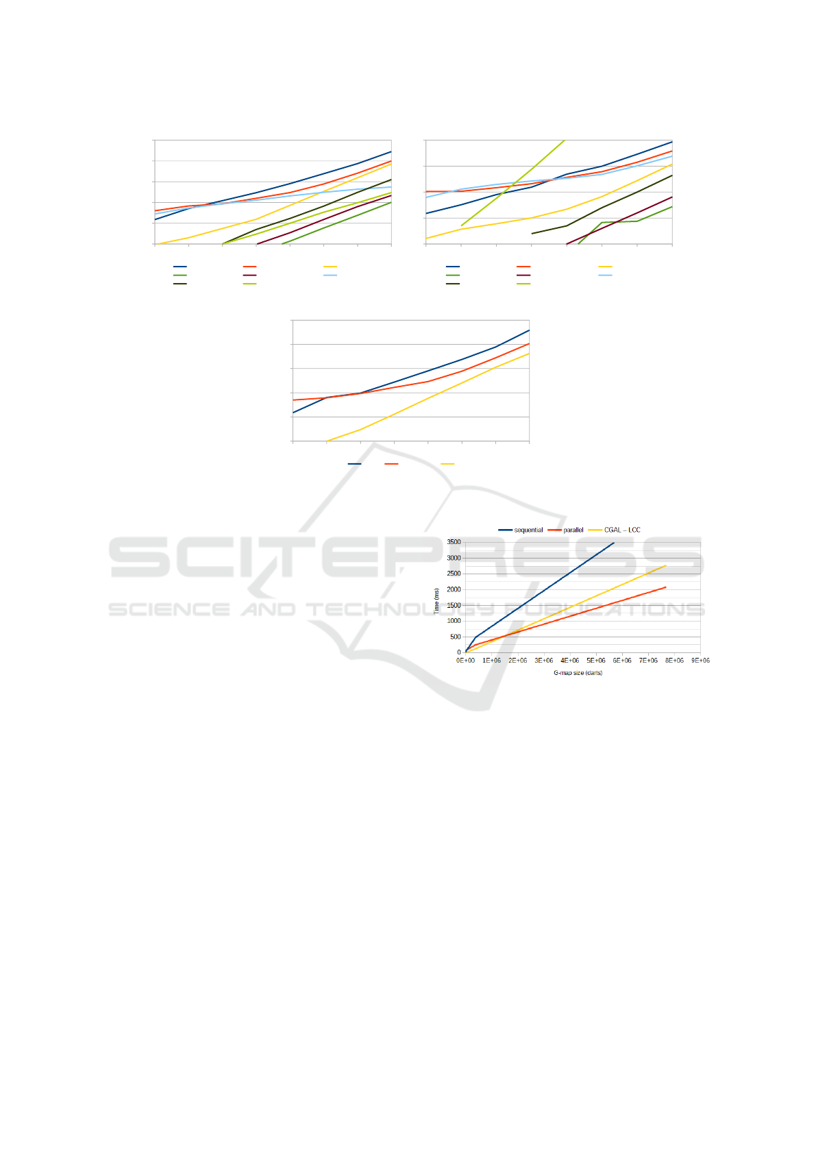
1 2 3 4 5 6 7 8
1
10
100
1000
10000
100000
Jerboa default Jerboa Parallel OpenFlipper
OpenSubDiv (CPU) OpenSubDiv (OpenMP) MeshLab
CGAL CGAL (LCC)
(a) Execution time for Loop
1 2 3 4 5 6 7 8
0,4
4
40
400
4000
Jerboa default Jerboa parallel OpenFlipper
OpenSubDiv (CPU) OpenSubDiv (OpenMP) MeshLab
CGAL CGAL (LCC)
(b) Execution time for Catmull-Clark
1 2 3 4 5 6 7 8
1
10
100
1000
10000
100000
Jerboa JerboaParallel CGAL
(c) Execution time for Doo-Sabin
Figure 7: Execution time for subdivision operations.
step is applied for each embedding (two embeddings
in our experiment: vertex position and face color) and
for each embedded value, the computation provided
by the user is called without any optimization.
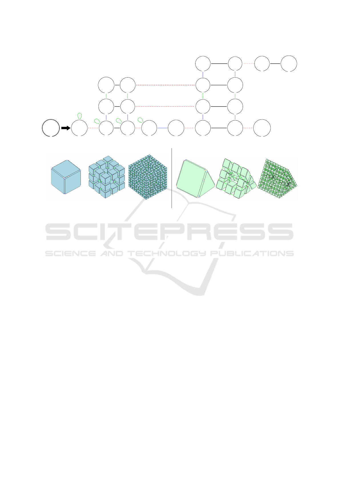
5.2 3D IFS
The Menger sponge operation is a good 3D fractal for
our purpose. Figure 9a presents the adaptation of this
operation. This rule follows all specificity of enrich-
ment operation and it is applied on a whole connected
component. The right hand side is complex and it
has twenty nodes (static checks of manifold condition
have been helpful to design such a rule). This oper-
ation is commonly applied on a cube for topological
purposes (Figs. 9b-9d) but we can directly apply this
rule on any object if it respects presented properties.
Figures 9e-9g present successive application of (the
same) Menger operation on a prism.
Figure 8 shows execution time of successive ap-
plications of this operation on a cube. The obtained
results are in accordance with those in 2D. Thanks to
parallelization, it is shown that the number of nodes
in the right hand side of a rule does not influence per-
formance. The yellow line represents execution time
of a C++ implementation of this computation devel-
oped in the CGAL LCC framework. We remark that
the parallel engine is best for the last iteration despite
the JVM behind it, whereas CGAL is programmed in
C++.
Figure 8: Execution time for Menger sponge rule.
6 CONCLUSION AND FUTURE
WORK
We have proposed an approach to parallelize some
operations in geometric modeling. More precisely,
we focused on so-called enrichment operations, that
is operations that make an object more complex and,
more generally, operations that aim at building ob-
jects. We relied on Jerboa structure and transforma-
tion method that is based on graph transformations.
Any enrichment operation must be expressed as a Jer-
boa rule, that is handled by a generic engine that has
been parallelized. This approach guarantees that any
operation that can be expressed as an enrichment op-
eration can benefit from the parallelization without
GRAPP 2020 - 15th International Conference on Computer Graphics Theory and Applications
134
<α0, α1, α2, α3>
n0
<_, α1, α2, α3>
n0
<_, _, _, _>
position
color
n18
<_, _, _, α3>
position
n3
<α0, _, _, _>
color
position
n12
<_, α2, α1, _>
position
color
n16
<_, _, α1, _>
color
position
n4
<_, _, α1, _>
color
position
n5
<α0, _, α2, α3>
color
position
n2
<_, _, _, _>
position
color
n8
<_, _, _, α3>
position
color
n6
<_, _, α1, _>
position
color
n17
<_, α2, _, _>
position
color
n13
<_, _, _, _>
position
color
n9
<_, _, _, _>
position
color
n15
<_, _, _, _>
position
color
n14
<_, _, α2, α3>
position
n1
<α0, _, _, α3>
position
color
n11
<α0, _, α2, _>
position
color
n19
<_, _, _, α3>
position
color
n10
<_, α1, _, α3>
position
n7
α2
α2
α0
α0
α2
α1
α2
α2
α3
α3
α2
α3
α3
α3
α2
α3
α0
α1
α0
α3
α0
α1 α0 α1
α1
α3
α0
α0
α1
α1
(a) Jerboa rule
(b) (c) (d) (e) (f) (g)
Figure 9: Menger operation and some applications.
the need for a dedicated study, that is, specifically-
studied parallelization of all the steps of the operation
as a classical geometric modeling approach would re-
quire.
Parallelization patterns have been identified in Jer-
boa’s generic Engine and two steps have been paral-
lelized: the topological transformation stage and the
management of embeddings. The used topological
structure is a key point of our approach since it offers
a fine-grained decomposition of the object that allows
us to deal with adjacency links of different dimension
separately.
The obtained results are clearly encouraging (x2
or x3 speed-up) and the optimization is satisfactory.
A conversion of this engine to C++ will probably give
us more efficiency when using multicore architectures
than Java Streams and will, hopefully, allow us to
compete with dedicated optimized methods. How-
ever, one point still needs attention: Only two steps
of the process have been parallelized. The first stage
of the process, that consists in filtering the part of the
object that is transformed and building the local ma-
trices that the parallel engine needs is still sequential.
Its parallelization requires to be able to walk through
a topological structure (a graph) in parallel but such
a walk-through requires critical sections that heav-
ily penalize performance. Another possible track to
get better performance is to port the engine presented
in this paper on GPU, since the matrices that it re-
lies on can be easily transferred to graphics memory.
Finally, the paper focuses on update and enrichment
rules. Some other, non local, rules, including several
input nodes and/or darts deletion, could be interesting
to parallelize as well.
REFERENCES
Belhaouari, H., Arnould, A., Gall, P. L., and Bellet, T.
(2014). Jerboa: A graph transformation library for
topology-based geometric modeling. In 7th Inter-
national Conference on Graph Transformation 2014,
volume 8571 of Lecture Notes in Computer Science,
pages 269–284.
Campagna, S., Kobbelt, L., and Seidel, H.-P. (1998). Di-
rected edges-A scalable representation for triangle
meshes. Journal of Graphics Tools, 3(4):1—-11.
Catmull, E. and Clark, J. (1978). Recursively generated
B-spline surfaces on arbitrary topological meshes.
Computer-Aided Design, 10(6):350––355.
Chen, J., Zhao, D., Zheng, Y., Huang, Z., and Zheng, J.
(2013). Fine-Grained parallel algorithm for unstruc-
tured surface mesh generation. In International Mesh-
ing Roundtable.
Cignoni, P., Callieri, M., Corsini, M., Dellepiane, M.,
Ganovelli, F., and Ranzuglia, G. (2008). MeshLab: an
Open-Source Mesh Processing Tool. In Eurographics
Italian Chapter Conference.
Coupez, T., Digonnet, H., and Ducloux, R. (2000). Parallel
Transparent Parallelization of Enrichment Operations in Geometric Modeling
135

meshing and remeshing. Applied Mathematical Mod-
elling, 25(2):153–175.
Damiand, G., Gonzalez-Lorenzo, A., Zara, F., and Dupont,
F. (2018). Distributed combinatorial maps for parallel
mesh processing. Algorithms, 11(8).
Damiand, G. and Teillaud, M. (2014). A Generic Im-
plementation of dD Combinatorial Maps in CGAL.
In Proc. of 23rd International Meshing Roundtable
(IMR), volume 82 of Procedia Engineering, pages 46–
58.
Doo, D. and Sabin, M. (1978). Behaviour of recursive di-
vision surfaces near extraordinary points. Computer-
Aided Design, 10(6):356 – 360.
Ehrig, H., Ehrig, K., Prange, U., and Taentzer, G. (2006).
Fundamentals of algebraic graph transformation.
EATCS Series “Monographs in Theoretical Computer
Science”. Springer-Verlag.
Gargallo-Peir
´
o, A., Houzeaux, G., and Roca, X. (2017).
Subdividing triangular and quadrilateral meshes in
parallel to approximate curved geometries. In 26th
International Meshing Roundtable.
Hutchinson, J. (1981). Fractals and self similarity. Indiana
University Mathematical Journal, 30(5):713–747.
Lienhardt, P. (1994). N-dimensional generalized combi-
natorial maps and cellular quasimanifolds. Interna-
tional Journal of Computational Geometry and Appli-
cations, 4(3):275–324.
Lipp, M., Wonka, P., and Wimmer, M. (2010). Parallel gen-
eration of multiple L-Systems. Computer and Graph-
ics, 34(5):585–593.
Loop, C. (2002). Smooth ternary subdivision of triangle
meshes. Curve and surface fitting, 10(6):3–6.
McCool, M., Robison, A. D., and Reinders, J. (2012).
Structured parallel programming. Elsevier/Morgan
Kaufmann, Amsterdam Boston.
Mlakar, D., Winter, M., Seidel, H.-P., Steinberger, M., and
Zayer, R. (2019). AlSub: fully parallel and modular
subdivision. https://arxiv.org/abs/1809.06047.
M
¨
obius, J. and Kobbelt, L. (2012). Openflipper: An open
source geometry processing and rendering frame-
work. In Curves and Surfaces, volume 6920 of Lec-
ture Notes in Computer Science, pages 488–500.
Nießner, M., Loop, C., Meyer, M., and DeRose, T. (2012).
Feature-adaptive GPU rendering of Catmull-Clark
subdivision surfaces. ACM Transactions on Graphics,
31(1).
Padr
´
on, E. J., Amor, M., B
´
oo, M., and Doallo, R. (2002).
Efficient parallel implementations for surface subdivi-
sion. In Fourth Eurographics Workshop on Parallel
Graphics and Visualization.
Polson, B. (2013). Opensubdiv from research to industry
adoption. In ACM SIGGRAPH 2013 Courses.
The CGAL Project (2019). CGAL User and Reference Man-
ual. CGAL Editorial Board, 5.0 edition.
GRAPP 2020 - 15th International Conference on Computer Graphics Theory and Applications
136
