
Integrating Assembly Process Design and VR-based Evaluation using the
Unreal Engine
Simon Kloiber
1 a
, Christoph Schinko
2
,Volker Settgast
2
, Martin Weinzerl
3
, Tobias Schreck
1
and Reinhold Preiner
1
1
Institute for Computer Graphics and Knowledge Visualization, Graz University of Technology, Austria
2
Fraunhofer Austria Research GmbH, Graz, Austria
3
AVL List GmbH, Graz, Austria
Keywords:
Virtual Reality, Unreal Engine, Integrated Design, Assembly Sequence, Training, Evaluation, Workflow.
Abstract:
To compete in industrial production and assembly design, companies must implement fast and efficient
workflows for the design of assembly processes. To date, these workflows comprise multiple stages that
typically cover a heterogeneous set of designer competences, used tools and data. We present a concept for an
integrated assembly process design workflow with VR-based evaluation and training methods leveraging the
flexibility and functionality of a modern game engine. Our approach maps the required tools onto off-the-shelf
features of these engines. This ensures an easy integration of our workflow into existing industry processes
and allows quick results, which support fast prototyping. Furthermore, Virtual Reality based previews and
evaluations significantly reduce the need for physical workstation prototypes, allowing for quicker feedback
and evaluation and early customer integration. We apply and evaluate our concept on an industrial assembly use
case for automotive traction batteries and give detailed insights into its adoption in practice and the advantages
over proprietary implementations.
1 INTRODUCTION
Creating workstations for a new assembly line is a
process combining design and engineering tasks. The
process consists of several stages, starting with the
construction of parts, that are needed to produce the
product. Some parts are given (machines, common
tools, etc.), others are newly defined. In the assembly
sequence design, the required work steps for the as-
sembly of sub-parts and parts are planned. The next
stage is to put it all together into an assembly prototype
and lay out the workstation. Finally, the result can be
tested for functionality, productivity and ergonomics
in the assembly simulation.
The conventional assembly planning process often
incorporates multiple applications in the tool chain.
The tools have to exchange data in a compatible for-
mat which can lead to dependencies to single vendors,
limiting flexibility. Especially computer aided design
(CAD) data is difficult to handle because it often in-
cludes detailed geometric data. In practice, an inter-
active visualization of CAD data requires conversion
to other file formats, data reduction and many manual
adjustments. Existing applications often create immer-
a
https://orcid.org/0000-0003-1186-7630
sive virtual reality (VR) test setups as read-only pre-
sentations without the possibility to send back changes
up this tool chain. Even small adjustments in the de-
sign lead to a complete recreation of layouts and test
setups.
In this paper, we present the concept for an assem-
bly design workflow integrating workstation layout,
sequence planning and training tasks, realized in a
modern game engine (Figure 1). We describe a map-
ping of the required tools onto ready-to-use features
of the engine and leverage VR to support the accelera-
tion and optimization of the entire assembly planning
process. This way, the engineers and designers can
get a spatial understanding of the assembly. These
insights can drive optimization before a physical pro-
totype needs to be built. Furthermore, interactions and
work steps can be simulated in VR using the same data.
This helps the design process through early feedback
from the people that will perform the assembly later
on. VR training lowers costs by delaying the need for
physical setups and by leaving real workstations for
productive tasks. Moreover, it reduces the risk when
training hazardous tasks.
Automated workflows are important for the cre-
ation of VR experiences. Only then is it possible to
quickly and cost efficiently update the virtual proto-
Kloiber, S., Schinko, C., Settgast, V., Weinzerl, M., Schreck, T. and Preiner, R.
Integrating Assembly Process Design and VR-based Evaluation using the Unreal Engine.
DOI: 10.5220/0008965002710278
In Proceedings of the 15th International Joint Conference on Computer Vision, Imaging and Computer Graphics Theory and Applications (VISIGRAPP 2020) - Volume 1: GRAPP, pages
271-278
ISBN: 978-989-758-402-2; ISSN: 2184-4321
Copyright
c
2022 by SCITEPRESS – Science and Technology Publications, Lda. All rights reserved
271

Product
Design
CAD
Feedback
Assembly
Sequence
Design
Workstation
Layout
Assembly
Evaluation
Datasmith
Game Packaging
Design
Review/
Training
Export App.
Feedback
Feedback Loop
Game Engine
VR
VR
3D
VR
Section 3.2 Sections 3.3 and 3.4 Section 3.4
Figure 1: Overview of the proposed integrated workflow for assembly process planning. After external product design, the
Unreal Engine provides functionality for sequence planning and workstation layout. These steps can be evaluated in VR
withing the engine. The application can be exported for design reviews and assembly training.
type for testing new design ideas and modified plans.
Our concept describes an efficient workflow that can
be integrated into existing industry processes. The
created content can be used directly for immersive
VR training and marketing purposes or can easily be
extended for creating instruction documents.
Our integrated workflow utilizes the Unreal En-
gine (Epic Games, 2019). By using a modern, source-
available game engine for assembly design and evalua-
tion, we ensure flexibility for extensions and indepen-
dence from tool vendors. The engine comes with state-
of-the-art graphics, support for different platforms and
VR setups, and a large developer community, making
it a sustainable solution.
2 RELATED WORK
Our workflow integrates three major stages of assem-
bly planning: assembly sequence design, workstation
layout and assembly simulation. The following will
cover related systems integrating these stages.
Assembly Sequence Design.
Assembly sequence
design uses CAD information to generate and evaluate
assembly sequences. Automated approaches use math-
ematical models based on data extracted from CAD
software (e.g., Zhang et al., 2019; Liu et al., 2019).
However, they focus on the generation of assembly
sequences and do not allow sequence exploration.
We are interested in interactive approaches to let
experienced designers influence the design and to al-
low some form of assembly simulation. For ease of
use, integration of product data management (PDM)
is an important step (Bowland et al., 2003). Scene
setup languages, like the virtual reality modeling lan-
guage (VRML), can help integrating 3D on different
platforms (Chung and Peng, 2008). Using a haptic
input device, like a haptic pen (Christiand et al., 2009),
improves the realism of a virtual environment, but also
reduces the flexibility of the system. These methods,
however, do not consider workstation layout, an im-
portant factor for assembly planning.
Workstation Layout.
Our integrated pipeline not
only supports modeling and simulation of assembly
sequences but also creating a layout for the respective
assembly workstation. An interesting rendering tech-
nique is a point cloud visualization for factory layout
planning (Gong et al., 2019). The system combines
traditional CAD rendering with point cloud data. It
allows for fast iteration cycles but does not incorporate
assembly sequence design. Choi et al. (2010) devised
a system that focuses on the design review of manufac-
turing plants and creates plant layouts automatically
based on rules and data extracted from an integrated
PDM system. While it provides an integrated VR visu-
alization, it does not allow for immersive interaction or
sequence design for individual workstations. An early
work that integrates layout design into VR also gives
feedback via constraints and through the simulation
of machines, but does not consider sequence planning
(Korves and Loftus, 1999). There also exists research
on factory layouts that includes assembly simulation
while evaluating the design (Michalos et al., 2018),
giving users a choice between creating the layout in a
desktop interface or in VR.
Integrated Assembly Design.
The Virtual Assembly
Design Environment (Jayaram et al., 1999) integrates
the aforementioned stages in a single system. It loads
workstation layout from CAD, and allows users to
design the layout and the assembly sequence in VR
only. Additionally, the system needs a more com-
plex setup than our approach, due to the integration of
VR gloves. A different integrated approach is infer-
ring constraints from assembly simulation (Jun et al.,
2005), focusing mainly on the generation of assembly
sequences. Mahdjoub et al. (2010) model the mechan-
ical design process using a multi-agent system. The
result is a collaborative platform that integrates the
different stages of assembly planning. CAD import,
assembly sequence design and assembly simulation
GRAPP 2020 - 15th International Conference on Computer Graphics Theory and Applications
272

are performed in a 3D desktop application, while de-
signers can modify the workstation in VR.
Al-Ahmari et al. (2016) integrate all aspects of assem-
bly process design into a virtual environment. Users
can collaboratively edit and design the assembly in
VR. Assembly sequence generation is reversed, since
the simulation of the assembly provides the sequence.
Delineation of Our Work.
Most of the discussed
work uses custom solutions with various frameworks
that cannot account for technological changes and re-
quire more manual development compared to modern
game engines. These engines are in constant develop-
ment and represent an abstraction layer for different
hardware and platform specifications. They provide
an evolving and flexible base for future modifications
and allow non-programmers to gain an insight and
to contribute (Hilfert and K
¨
onig, 2016; Braatz et al.,
2011). We use the Unreal Engine, because it gives us
a well-maintained base for development and offers a
wealth of additional tools (e.g., flexible CAD import).
Automated approaches for assembly sequence de-
sign have not been adapted by industry, and commer-
cial systems rely on experts and manual interaction
(Ou and Xu, 2013). An implementation for manual
interaction within a game engine, however, provides
a sustainable and flexible environment. We focus on
perceptual and cognitive feedback (Boud et al., 2000)
in VR. Previous work (Gallegos-Nieto et al., 2017; Li
et al., 2018; Sagardia et al., 2016; Wang et al., 2018)
can integrate haptic and motor-skills feedback only via
specialized haptic tools or large or expensive setups.
Instead, we rely purely on the tracking of head and
controllers and their feedback (i.e. vibration), for more
flexibility. There are many commercial tools, which
focus mostly on CAD export and non-interactive CAD
visualization, without addressing the whole assembly
planning workflow. They are also often tied to larger,
more expensive CAD systems.
With these considerations, the implemented con-
cept can create a lasting basis for integrated assembly
process planning in an industrial context. In summary,
the contributions of this paper are:
•
A concept for an integrated assembly design work-
flow that allows for faster and more efficient as-
sembly process design.
•
A description of a realization of this workflow in
an existing modern game engine, alleviating its
reproduction and maintenance effort. This enables
•
the incorporation of a ready-to-use VR front-end,
allowing for in situ evaluation and testing, and
early customer integration, ultimately accelerating
the assembly design process.
3 PROPOSED WORKFLOW
3.1 Overview
Our concept integrates multiple tasks in the assembly
process design into one environment inside the Unreal
Engine. Figure 1 shows an overview of the whole
workflow. We consider five major stages throughout
the whole product development process: 1) product
design, 2) assembly sequence design, 3) 3D assembly
workstation layout and 4) assembly evaluation, and
5) assembly simulation. The product design phase
occurs outside of our environment: designers plan the
product in a CAD environment and import it into the
implemented system for quick feedback. Assembly
sequence design can either be performed inside the
system or outside, depending on the respective prefer-
ences. Since Unreal Engine has a scene graph editing
functionality built in, workstation layout is performed
inside the engine with imported assets.
Assembly evaluation is performed during the de-
sign of the assembly process by starting the VR ap-
plication from within the engine and by reproducing
its steps virtually. Finally, design review or assem-
bly training is performed by simulating the assembly
outside the game engine as a packaged standalone
application.
3.2 CAD Data Processing
The first step in the presented pipeline is the processing
and conversion of CAD data of a product to allow for
an import into the game engine. For virtual assembly
design and simulation, finely detailed components as
typically present in CAD data, are not needed. A
simplified structure tailored towards the assembly use
case not only benefits the design process but also helps
the underlying game engine to maintain performance.
Moreover, CAD formats use geometrically exact
formulations that are not directly suitable for interac-
tive visualization, where surfaces are typically repre-
sented by a mesh of triangles. To obtain such a repre-
sentation, we need to tessellate the CAD geometry and
perform tasks like mesh healing and UV-coordinate
generation for texturing. Unnecessary interior geom-
etry is discarded and a defeaturing step removes all
non-essential elements. For automated CAD data pro-
cessing, we use the Unreal Engine’s Datasmith func-
tionality together with Python scripting (Convard et al.,
2018). However, we also rely on specific additional
metadata not provided by the CAD files.
To import and assign materials to the imported
meshes, we rely on a pre-defined library of materials
(or shaders) available in the game engine. In case a
Integrating Assembly Process Design and VR-based Evaluation using the Unreal Engine
273
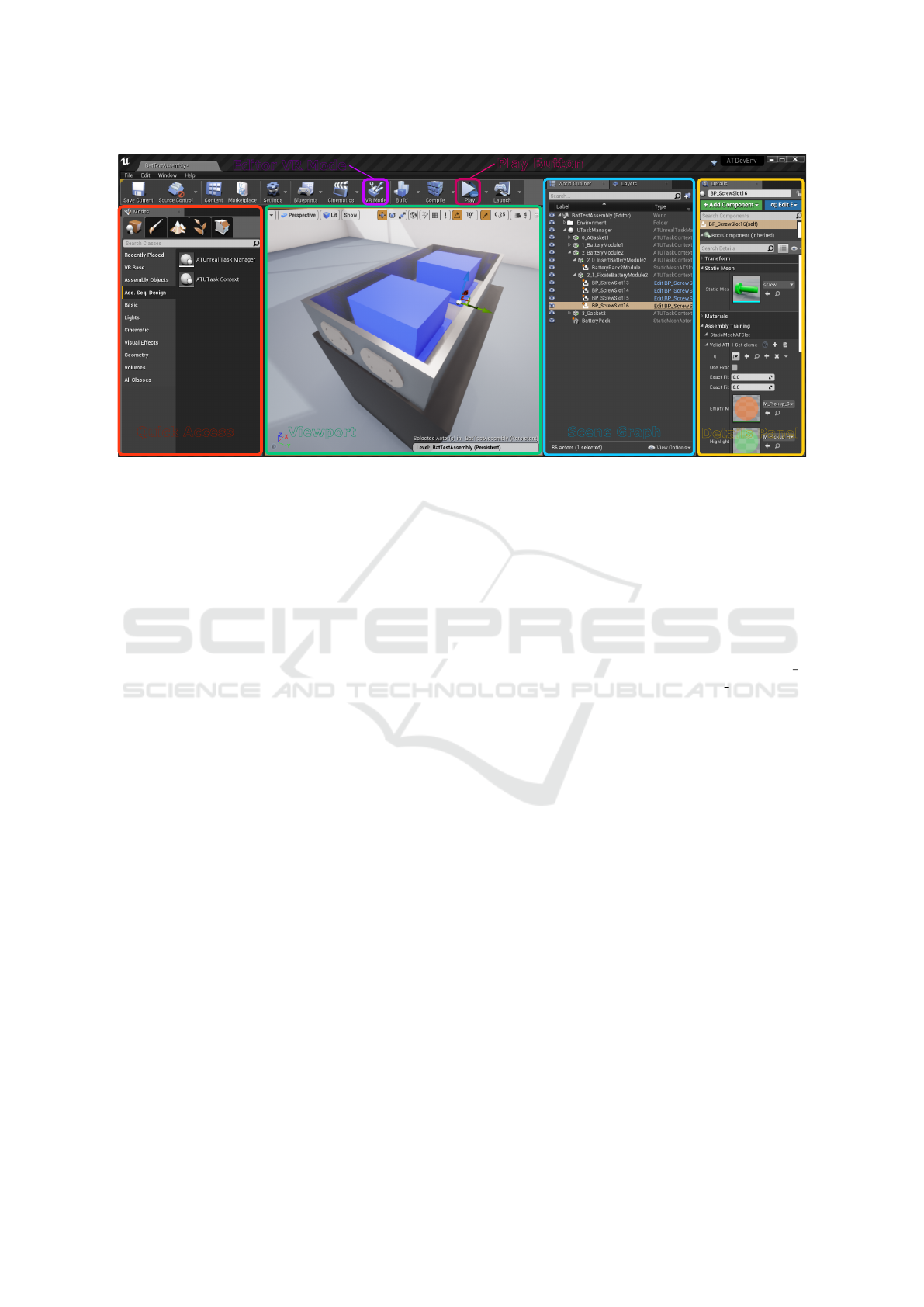
Viewport
Quick Access
Scene Graph
Details Panel
Editor VR Mode
Play Button
Figure 2: The Unreal Engine editor with the important parts for our workflow: quick access of important objects (left), 3D
viewport (middle), scene graph (right) and details panel (far right). The toolbar (top) contains buttons for switching to the
editor’s VR mode and for quickly launching the application in either desktop or VR mode.
mapping to these library materials is available (e.g.
in the form of metadata), it is used. Otherwise, a
meaningful assignment of target materials is obtained
by looking for specific tags within the part identifier
(red, metal, wood, . . . ). If no matches can be found,
we take the nearest matching library materials in RGB
color space based on a Euclidean distance measure.
3.3 Integrated Assembly Sequence and
Workstation Design
Integrating assembly sequence design with laying out
a workstation necessitates different design modalities:
logical design and spatial design. Modern game en-
gines can provide both these modalities off-the-shelf
via their editable scene graph and a 3D viewport.
Assembly Sequence Design.
To integrate our goals
into the Unreal Engine, we have implemented a hier-
archical task system and a generalized object model.
Figure 2 gives an overview of the Unreal Engine editor
with the interface elements that are important for our
conceptualized workflow. Designers can use the Quick
Access panel to drag elements into the Viewport to
position them and define their hierarchies in the Scene
Graph, or ‘world outliner’. Designers define an assem-
bly sequence by creating a hierarchy of ‘task’ elements
in the scene graph. The task order is defined by the or-
der of siblings. To define the necessary actions for task
completion, designers can drag conditional elements
from the Quick Access panel onto tasks. These condi-
tions have a representative geometry in the scene and
require the insertion of objects to be fulfilled. The root
of the task hierarchy is defined by a ‘task manager’
element. In the given example, we have created an
assembly process design for assembling a battery pack
with two modules (blue) and two gaskets (shown in
the outside of the battery pack). This process consists
of a set of subtasks for assembling each component.
The assembly task of battery module 2 is split into two
subtasks: the insertion of the module itself (task 2 0)
and its fixation with four screws (task 2 1).
Workstation Layout.
For workstation layout, design-
ers can use the 3D viewport (cf. Figure 2), or the VR
mode integrated in the game engine’s editor, which
provides a better understanding of the spatial setup.
The VR mode can also start the application to test the
changes without having to put down the head-mounted
display. Figure 4 (background) shows an exemplary
workstation with the needed parts.
Implementation.
We have realized our concept as a
plugin for the Unreal Engine. It is mostly done in C++
and is designed to be flexible and expandable through
the visual scripting language of the engine (Blueprints)
that is designed for use by non-programmers. The
implementation is based on a hierarchical task model
and a generalized object model (Fig. 3).
Task Model.
Tasks are holding the logical order de-
fined by their task contexts in the scene graph. A task
context is the scene graph representation of a task; it
has a 3D position but has no visual representation. It
contains other task contexts to form child tasks, condi-
tions for its fulfillment and other objects related to the
task. Tasks are completed when all child tasks are fin-
ished and all conditions of its task context are fulfilled.
GRAPP 2020 - 15th International Conference on Computer Graphics Theory and Applications
274

Task
Manager
UTask
Context
UTask
Manager
Task Model
Object Model
Grabbable
Material
Tool
Condition
Slot
Event
Handler
Unreal Engine
Task
Task
Context
Figure 3: Task model for sequence planning (blue, left) and
generalized object model (red, right).
This separation of logical order and scene representa-
tion ensures that the task system can be re-used in other
development environments. A task manager initializes
the task structure from its contained task contexts at
the beginning of the application and is responsible for
task event handling. Figure 3 shows the task model
and the Unreal Engine representation of task contexts
and the task manager, which link the needed behavior
to the game engine. Task contexts hide contained ob-
jects and conditions until they become active. When
tasks are a part of a larger assembly, designers can
choose whether objects contained in the task should
remain visible after the task is completed.
Generalized Object Model.
To define the assembly
and its contained elements, we have implemented a
generalized object model (c.f. Figure 3). Assembly
interaction boils down to slot conditions, assembly
materials and tools. Unlike tasks, these objects have
a visual representation in the scene. Slot conditions
comprise the basis for task completion. In the Details
Panel, designers specify the mesh that visually repre-
sents the slot (cf. the screw mesh in Figure 2) and a
set of assembly materials that will fulfill the slot con-
dition, when inserted into the slot. Figure 4 (green)
shows the visual representation of an assembly slot
within a VR scene. Assembly materials are parts that
are used for the assembly. In a VR simulation, they
can be picked up by hand or via tool and are assem-
bled at slot conditions. Designers can decide when to
reveal the needed assembly materials. When placed
outside the task hierarchy, users can always see them
and interact with them. However, when they reside as
a child node of a task in the scene graph, they will be
hidden until the task becomes active. Tools are held
objects that can interact with materials and can insert
them into slot conditions. Instances of these three ele-
ments of the object model will be present in the quick
access panel of the editor, so that designers do not have
to browse through all contents of an Unreal Engine
project (cf. Assembly Objects in the quick access panel
in Figure 2). An event handler serves as a communica-
tion bridge between different object types as it keeps a
record of all relevant objects at runtime. This allows
for efficient event handling between objects. We have
evaluated our model on a battery assembly use case
Figure 4: The arm of the added avatar and the slot highlight
(green) while inserting a part into a battery pack. An ex-
emplary workstation containing all necessary parts for the
assembly sequence resides in the background.
and we have found that this object model covers all
necessary steps of a typical assembly process. If more
functionality is needed for a different application, its
modular design allows further extension.
3.4 VR Integration
When designers want to evaluate their assembly design,
they can either do so as a desktop application or in
virtual reality. The application can be started from
within the engine’s editor or be packaged to share it
with others. Designers can quickly alter their design,
test it in VR and apply modifications within minutes,
which allows for short iteration times. Sharing the
application allows designers to gather feedback or to
use it for training when the design is finished. An
interactive design review is also possible, where one
person can alter and present the result to others on
screen. To speed up the evaluation process, we enable
designers to jump to a certain point in the assembly
process, without having to perform all preceding steps.
For intuitive interaction with the assembly in VR,
we have focused on supporting a fast and direct setup
of VR hardware. Hence, only the headset and the con-
trollers are necessary. The main advantage of VR in
this context is providing an insight early in the develop-
ment and without a physical prototype. Hence, we find
that it is more conductive to experience the assembly
at a cognitive level instead of trying to represent every
motor-skill detail.
Virtual environments can take advantage of giving
users more feedback than would be possible in a real
setup (Carlson et al., 2015). To this end, whenever
a user holds a material, either by hand or tool, we
highlight corresponding slots. To also give ergonomic
feedback, we have created a player avatar in VR that
shows whenever the arms collide with the environment.
Figure 4 shows the user’s view when fitting an insert
into a battery pack.
Integrating Assembly Process Design and VR-based Evaluation using the Unreal Engine
275

Thermal System
Gaskets
Battery Modules
Stiffener
Battery Housing
Figure 5: Exploded view of our simplified traction battery.
4 EVALUATION AND FEEDBACK
We evaluate our concept workflow based on a case
study of the assembly process design of automotive
traction batteries. This is a highly relevant use case
due to the increased focus on electric vehicles. For
this work, we have recreated a simplified version of an
industrial production CAD geometry (c.f., Figure 5).
The simplified battery consists of a thermal system be-
neath two battery modules, a stiffener for the housing,
two gaskets and a silver battery housing. This equates
to
37
individual parts requiring
12
assembly steps in
total, where, e.g., the insertion of a group of
4
screws
counts as a single step. We have studied the assembly
sequence design process of this model by observing
two VR experts and have gathered informal feedback
from industry experts that are involved in the develop-
ment and assembly of traction battery prototypes for
supporting vehicle development programs.
4.1 Experimental Evaluation
To evaluate our workflow, we let two VR experts use
our system to define an assembly sequence for the
battery shown in Figure 5. The first expert has worked
only with the back-end of the engine, while the second
expert has experience with other game engines. Both
had little to no experience with scene editing in the
Unreal Engine. Hence, they are fitting subjects to
verify the ease of use of editing assembly sequences.
Each evaluation session consisted of three parts.
First, a short introduction to the editing process within
the Unreal Engine editor and our introduced models
(Figure 3). Then, the participants were presented an
exploded view of the battery part (Figure 5) as well
as its fully assembled state. Based on this, they mod-
eled an assembly sequence for the given battery model,
using our object and task model in the 3D viewport
and the Scene Graph view (Figure 2), and running
intermediate assessments of their modeled steps when-
ever needed. During this process, we measured the
iteration times between sequence design and VR evalu-
ations. Lastly, the experts filled out a System Usability
Score (Brooke, 1996) and gave feedback.
Design Process.
Overall, the workflow in the Un-
real Engine editor was well received. The participants
quickly knew how to operate the software and knew
what to do after a short learning period. Figure 6 shows
how the participants’ speed for creating the sequence
increased over time. The timelines of both participants,
their VR sessions and the amount of parts mapped to
the assembly process between VR sessions are shown.
Participant
2
had more experience with scene model-
ing and finished the whole assembly process after
77
minutes, while participant
1
required more time and
could not finish the design in the available time. Both
participants designed different assembly sequences,
starting with different parts of the battery. The VR
evaluation sessions each lasted less than two minutes
since the participants only needed to check the changed
parts of the assembly sequence.
Participant Feedback.
The participants found the
generalized object model helpful in ensuring ease of
use of the system and liked editing the sequence in the
scene graph. While the work is not difficult, they stated
that more repetitive tasks should be automated and that
a better modeling guidance is needed–especially for
novice users. In general, they found VR for an in
situ verification very useful. It helped them to gain
an insight into the movements and enabled checking
for accessibility issues. Participant
1
also used VR for
planning at the beginning, by checking which parts
need to be assembled first. The participants would
use the system frequently if they needed to design
assembly sequences. Participant
2
stated that people
with experience in 3D scene editing tools should have
no problem using our workflow. Participant
1
gave a
system usability score of
60
and participant
2
gave a
score of
85
out of a possible
100
. The low score of
participant
1
is in part due to little experience with
scene editing and would improve over repeated use.
The real traction battery prototype that served as a
reference for our simplified version, consists of about
80
assembly steps of comparable complexity. Pro-
jecting the timings for the
12
steps of our relatively
inexperienced participants to these
80
steps results
in only about one day’s work to model the assembly
sequence for the real battery.
4.2 Industrial Impact
Our proposed workflow was designed for industrial as-
sembly sequence designs for prototypical applications.
This section will discuss the impact of our workflow
GRAPP 2020 - 15th International Conference on Computer Graphics Theory and Applications
276

Participant 1
Participant 2
+1
+1
+2
+2
+4
+2 +2 +2
6/12
+2
12/12
0min
80min
Virtual Reality
UE Editor
Steps
Steps
Figure 6: A timeline of the behavior and progress of both
participants in the experimental evaluation. The piece-wise
increments denote the number of integrated steps into the
assembly sequence between evaluation cycles.
and give informal feedback from domain experts.
Conventional Assembly Design Process.
The cur-
rent development process of a battery pack consists
of three stages. In the first stage (
30
work days), the
assembly sequence, work instructions, the tools and
fixtures are planned based on a 3D CAD model. The
second stage is a test run to train and verify the work in-
structions at the production site (five workdays). Since
the parts of the battery pack are prototypes themselves,
supplier delivery hold-ups often lead to a delay of the
assembly test run phase by another 14 to 30 days. The
third stage is a feedback loop for fixing all issues found
during the verification over at least 5 more workdays.
Expert Feedback.
For gathering domain expert feed-
back, we first let an industry VR application designer
test our workflow in the Unreal Engine editor to cre-
ate a reality-based demonstrative VR application. The
workflow was then presented to experts involved in
the battery assembly process design and they could try
out the virtual assembly. The VR designer found the
use of the task system intuitive and expressed interest
in further using the implemented features for the cre-
ation of assembly sequence demonstrations. Experts
responsible for the execution of the assembly process
found that our concept would improve their design
process. They highlighted the advantage of having
no safety issues in the virtual environment during the
evaluation and testing of the assembly, as battery mod-
ules are normally fully charged during a real-world
assembly. Most importantly, the experts pointed out
the significant cost benefit of a low-cost game engine,
given the fact that alternative commercial solutions
or custom in-house development would either pose
high running cost or require a high initial investment.
While in VR, the experts found that the assembly table
was too low, which underlines the advantage of spatial
intuition and ergonomic feedback of accelerated VR
feedback cycles.
Integrated Assembly Design Process.
At the mo-
ment, the first phase in the design process takes the
majority of the overall time expense, since currently,
all aspects of the assembly process have to be incorpo-
rated in the planning at once. The experts estimate the
cost of representing the assembly process in our con-
cept workflow at
10%
of the overall time requirement
of the first development stage, and a reduced time ef-
fort of
40 − 60%
for the last two stages of their current
design process pipeline. However, a roll-out of our
integrated concept workflow would introduce a more
agile and thus efficient design process in the first devel-
opment stage; from one long planning stage involving
all aspects of the assembly planning at once, to sev-
eral shorter planning cycles supported by intermediate
VR-based evaluation sessions.
5 DISCUSSION
The evaluation showed that interaction in VR is intu-
itive, but visual aid during assembly is lacking. While
a whole-body avatar in VR gives the user a stronger
sense of presence (Jerald, 2016), visualizing only the
arms of the avatar might be sufficient for most appli-
cations. To avoid artifacts, more than head and hand
tracking would be needed, at the cost of setup time
and mobility. The availability of a machine-readable
assembly sequence description for the import process
would enable optimization tasks and provide necessary
information for all subsequent design steps.
We want to simplify the Unreal Engine editor for a
better guidance of inexperienced users. The visualiza-
tion of and guidance for safety hazards when assem-
bling is an important next step, as it allows training
for hazardous situations in a safe environment. We
also want to integrate more in-depth analysis of sta-
tistical and ergonomic data into the feedback loop of
the virtual environment to give a better insight into
the assembly process. Furthermore, we would like
to automate the generation of documentation and in-
structional animations of the assembly process and use
automated assembly sequence generation as a starting
point for the assembly sequence design.
6 CONCLUSION
We have created a conceptual integrated workflow for
assembly process design. We leverage the tools offered
by the Unreal Engine to integrate assembly sequence
design and workstation layout. When combined with
VR evaluation and training, this means less invested
time and greater error prevention via early and fast
iteration cycles. To achieve this, CAD data can be
imported into the engine and mapped to an assem-
bly object model. A hierarchical assembly sequence
model within the scene graph allows for quick setup
and insight into the assembly process design. Using a
Integrating Assembly Process Design and VR-based Evaluation using the Unreal Engine
277

game engine provides an abstraction layer and flexibil-
ity in terms of features, visual fidelity and VR systems.
The devised workflow aims at creating a low barrier
of entry for industrial applications such that it can be
used in existing production processes with little effort.
ACKNOWLEDGEMENTS
We thank Alexander Pagonis and Jasmin Armbr
¨
uster
for their valuable input in this project. This work is
supported by the Austria Research Promotion Agency
(FFG) within project Virtual Reality for Cognitive
Products and Production Systems (grant No.: 864814).
REFERENCES
Al-Ahmari, A. M., Abidi, M. H., Ahmad, A., and Dar-
moul, S. (2016). Development of a virtual manufac-
turing assembly simulation system. Adv. Mech. Eng.,
8(3):168781401663982.
Boud, A. C., Baber, C., and Steiner, S. J. (2000). Virtual
reality: A tool for assembly? Presence Teleoperators
Virtual Environ., 9(5):486–496.
Bowland, N., Gao, J., and Sharma, R. (2003). A PDM- and
CAD-integrated assembly modelling environment for
manufacturing planning. J. Mater. Process. Technol.,
138(1-3):82–88.
Braatz, D., Toledo, F. M., Tonin, L. A., Da Costa, M. A. B.,
and Menegon, N. L. (2011). Conceptual and method-
ological issues for the application of game engines in
designs of productive situations. In 21st Int. Conf. Prod.
Res. Innov. Prod. Prod. ICPR 2011 - Conf. Proc.
Brooke, J. (1996). SUS - A quick and dirty usability scale.
Usability Eval. Ind., 189(194):4–7.
Carlson, P., Peters, A., Gilbert, S. B., Vance, J. M., and
Luse, A. (2015). Virtual Training: Learning Transfer
of Assembly Tasks. IEEE Trans. Vis. Comput. Graph.,
21(6):770–782.
Choi, S., Jo, H., Lee, J., and Noh, S. D. (2010). A rule-
based system for the automated creation of VR data
for virtual plant review. Concurr. Eng. Res. Appl.,
18(3):165–183.
Christiand, Yoon, J., and Kumar, P. (2009). A novel optimal
assembly algorithm for haptic interface applications of
a virtual maintenance system. J. Mech. Sci. Technol.,
23(1):183–194.
Chung, C. and Peng, Q. (2008). Enabled dynamic tasks plan-
ning in Web-based virtual manufacturing environments.
Comput. Ind., 59(1):82–95.
Convard, T., Picon, F., and Wilken, M. (2018). Acceler-
ating Data Conversion and Visualization–Automating
CAD data preparation and real-time visualization using
Unreal Studio. Technical report, Epic Games.
Epic Games (2019). Unreal engine. https://www.
unrealengine.com.
Gallegos-Nieto, E., Medell
´
ın-Castillo, H. I., Gonz
´
alez-
Badillo, G., Lim, T., and Ritchie, J. (2017). The anal-
ysis and evaluation of the influence of haptic-enabled
virtual assembly training on real assembly performance.
Int. J. Adv. Manuf. Technol., 89(1-4):581–598.
Gong, L., Berglund, J., Fast-Berglund,
˚
A., Johansson, B.,
Wang, Z., and B
¨
orjesson, T. (2019). Development of
virtual reality support to factory layout planning. Int. J.
Interact. Des. Manuf., 13(3):935–945.
Hilfert, T. and K
¨
onig, M. (2016). Low-cost virtual reality
environment for engineering and construction. Vis.
Eng., 4(1):2.
Jayaram, S., Jayaram, U., Wang, Y., Tirumali, H., Lyons,
K., and Hart, P. (1999). VADE: A Virtual Assembly
Design Environment. IEEE Comput. Graph. Appl.,
19(6):44–50.
Jerald, J. (2016). The VR Book. Association for Computing
Machinery and Morgan & Claypool, New York, NY,
USA.
Jun, Y., Liu, J., Ning, R., and Zhang, Y. (2005). Assembly
process modeling for virtual assembly process plan-
ning. Int. J. Comput. Integr. Manuf., 18(6):442–451.
Korves, B. and Loftus, M. (1999). The application of immer-
sive virtual reality for layout planning of manufacturing
cells. Proc. Inst. Mech. Eng. Part B J. Eng. Manuf.,
213(1):87–91.
Li, J. R., Liu, J. W., Wang, Q. H., and Hu, G. H. (2018). A
staged haptic rendering approach for virtual assembly
of bolted joints in mechanical assembly. Int. J. Adv.
Manuf. Technol., 96(1-4):161–171.
Liu, Z., Nan, Z., Qiu, C., Tan, J., Zhou, J., and Yao, Y.
(2019). A discrete fireworks optimization algorithm
to optimize multi-matching selective assembly prob-
lem with non-normal dimensional distribution. Assem.
Autom., 39(2):323–344.
Mahdjoub, M., Monticolo, D., Gomes, S., and Sagot, J.-C.
(2010). A collaborative Design for Usability approach
supported by Virtual Reality and a Multi-Agent Sys-
tem embedded in a PLM environment. Comput. Des.,
42(5):402–413.
Michalos, G., Karvouniari, A., Dimitropoulos, N., Togias,
T., and Makris, S. (2018). Workplace analysis and
design using virtual reality techniques. CIRP Ann.,
67(1):141–144.
Ou, L.-M. and Xu, X. (2013). Relationship matrix based
automatic assembly sequence generation from a CAD
model. Comput. Des., 45(7):1053–1067.
Sagardia, M., Hulin, T., Hertkorn, K., Kremer, P., and
Sch
¨
atzle, S. (2016). A platform for bimanual virtual
assembly training with haptic feedback in large multi-
object environments. In Proc. ACM Symp. Virtual Real.
Softw. Technol. VRST, volume 02-04-November-2016,
pages 153–162, New York, USA. ACM Press.
Wang, Q. H., Huang, Z. D., Li, J. R., and Liu, J. W. (2018). A
force rendering model for virtual assembly of mechani-
cal parts with clearance fits. Assem. Autom., 38(2):173–
181.
Zhang, N., Liu, Z., Qiu, C., Hu, W., and Tan, J. (2019). Opti-
mizing assembly sequence planning using precedence
graph-based assembly subsets prediction method. As-
sem. Autom., ahead-of-print(ahead-of-print).
GRAPP 2020 - 15th International Conference on Computer Graphics Theory and Applications
278
