
High Speed Measurement in Spectral Drill using Q-plate and Camera
Seigo Ohno
1 a
, Katsuhiko Miyamoto
2 b
, Shin’ichiro Hayashi
3 c
and Norihiko Sekine
3
1
Department of Physics, Tohoku University, 6-3, Aza-Aoba, Aoba-ku, Sendai, Japan
2
Department of Materials Science, Chiba University, 1-33, Yayoi-cho, Inage-ku, Chiba, Japan
3
Terahertz Technology Research Center, National Institute of Information and Communications Technology,
4-2-1 Nukui-Kitamachi, Koganei, Tokyo, Japan
Keywords:
Geometric Phase, Berry Phase, Fabry-P
´
erot Cavity.
Abstract:
We have proposed a method to scan resonance modes in a Fabry-P
´
erot cavity applying a geometric phase
shifter, named as spectral drill. When the geometric phase shifter consists of two quarter wave plates and a
half wave plate sandwiched by them is put into a cavity, the resonance modes can be scanned by the rotation
of the half wave plate. Since a mechanical rotation stage has been used for scanning the cavity in our prior
works, the scanning rate was limited by the rotational speed of the stage. In this work, by replacing the half
wave plate to a q-plate with removing the mechanical stage and by taking transmission images by a camera,
we succeeded in 720 times faster acquisition of the transmission spectrum of the spectral drill.
1 INTRODUCTION
Regular separation of resonance modes of a Fabry-
P
´
erot (FP) cavity in the spectral region has been used
as a spectral ruler and has been applied to a frequency
marker for the fine spectroscopy and the essential
principle of a frequency comb(Del’Haye et al., 2009).
Since the frequency separation between the resonance
modes depends on the cavity length d, the resonance
frequency can be scanned by changing the cavity
length. The maximum scanning frequency range in
the FP cavity is restricted by physical limitations of
the cavity mirror position or by the tunable range of
physical properties defining the effective light path
length within the cavity. For instance, one of cavity
mirrors is supposed to be mounted on a piezo manip-
ulator for scanning along optical axis. In such case,
the scanning length is limited to only micron order. It
may be enough length for visible light, but short for
the IR range, in which the wavelength becomes longer
than one micron. Other problem for piezo scanner is
on its hysteresis. For the precise measurement, one
has to take care about the reproducibility of the fre-
quency axis because of a piezo hysteresis.
A geometric phase experienced by a light whose
polarization state moves on a Poincar
´
e’s sphere is
a
https://orcid.org/0000-0002-8414-9181
b
https://orcid.org/0000-0002-2611-882X
c
https://orcid.org/0000-0002-8570-8504
understood as the analogy of the Berry phase ex-
perienced by the wave-function of electron propa-
gating in a vector field. The geometric phase of a
light had been investigated by Puncharatnum in old
days(Pancharatnam, 1956). As an application of the
geometric phase of a light, a geometric phase shifter
(GPS) consists of a simple series of phase plates has
been also proposed by some groups for precise con-
trol of the optical phase(Yang et al., 2010) and the
THz-wave phase(Kawada et al., 2016). Recently, the
geometric phase has attracted many researches be-
cause the metasurface technology can control such
geometric phase of a light by designing artificial
structures(Huang et al., 2012).
We have previously reported an optical configu-
ration named “spectral drill,” in which a GPS is put
into a FP cavity. In the spectral drill, the resonance
frequency of the FP cavity can be swept continuously
with seamless manner by rotating a phase plate con-
sisting the GPS(Ohno, 2018). The motion of reso-
nance modes moving on the spectral region with ro-
tating the phase plate looks like apparent motion of
grooves on a drill with the rotation. This behavior is
responsible for the name of spectral drill. Since, in
our previous system, the phase plate was mounted on
an auto-rotational stage, the scanning speed of the res-
onance modes was limited by the rotational speed of
the mechanical movement. In this paper, we propose
a method to break this limitation by replacing a phase
plate with a q-plate and using a camera.
Ohno, S., Miyamoto, K., Hayashi, S. and Sekine, N.
High Speed Measurement in Spectral Drill using Q-plate and Camera.
DOI: 10.5220/0008959400970099
In Proceedings of the 8th International Conference on Photonics, Optics and Laser Technology (PHOTOPTICS 2020), pages 97-99
ISBN: 978-989-758-401-5; ISSN: 2184-4364
Copyright
c
2022 by SCITEPRESS – Science and Technology Publications, Lda. All rights reserved
97
We believe this method will open new spectro-
scopic applications of a spectral drill.
2 SPECTRAL DISTRIBUTION
A GPS consists of the series of one quarter wave plate
(QWP), a half wave plate (HWP), and another QWP.
The fast axis of two QWPs are respectively tilting by
+/ − 45 degrees from the polarization direction of an
incident light. In a usual GPS setup, HWP can be ro-
tated with mounting on a rotational stage(Yang et al.,
2010; Kawada et al., 2016; Ohno, 2018). When the
rotational angle of the HWP is α, the light experi-
ences the geometric phase delay of 2α. Consequently,
a GPS within a FP cavity makes the confined light get
the phase delay of 4α per one round trip. In this case,
the transmission intensity of the cavity can be given
as (Ohno, 2018),
I/I
0
=
1 +
4R
(1 − R)
2
sin
2
(kd + 2α)
−1
, (1)
where, I
0
, k, d, and R are the intensity and wavenum-
ber of the incident light, the cavity length, and re-
flectance of the cavity mirrors, respectively. Note that
we assumed all of the reflectance of the cavity mirrors
are the same to be R. When the values of reflectance
are different and/or the cavity has energy loss by some
reasons, 1−R
2
can be treated as the effective loss in a
round trip within the cavity. Now, we consider to re-
place the HWP in the GPS with a q-plate. A q-plate is
made of anisotropic molecules, like a liquid crystal or
its polymerized material. It partially works as a HWP,
but the fast axis is gradually rotated m/2 times around
the center of the optics, and is usually used for gen-
erating an optical vortex beam with the topological
charge of m(Marrucci, 2013; Sanchez-Lopez et al.,
2018). When such GPS is introduced into the FP cav-
ity, the transmission intensity distribution in the polar
coordinates (r,θ), whose origin is set onto the cen-
ter of the q-plate, can be derived through modifying
Eq.(1) as,
I(r, θ) = G(r) ·
1 +
4R
(1 − R)
2
sin
2
(kd + 2α(θ))
−1
,
(2)
where, G(r) is the beam power distribution in radial
direction. α(θ) is the tilting angle of the fast axis at
the partial area at the azimuthal position θ on the q-
plate. In mth-order q-plate, the tilting of the fast axis
is distributed as α(θ) =
m
2
θ. This means that the reso-
nance condition of kd +mθ = nπ with an integer value
n can be satisfied 2m times around the center of the
q-plate. Hence, when we measure the transmission
image around the optical axis of this system, we will
observe 2m fringes in the azimuthal direction around
the center.
3 EXPERIMENT
3.1 Experimental Setup
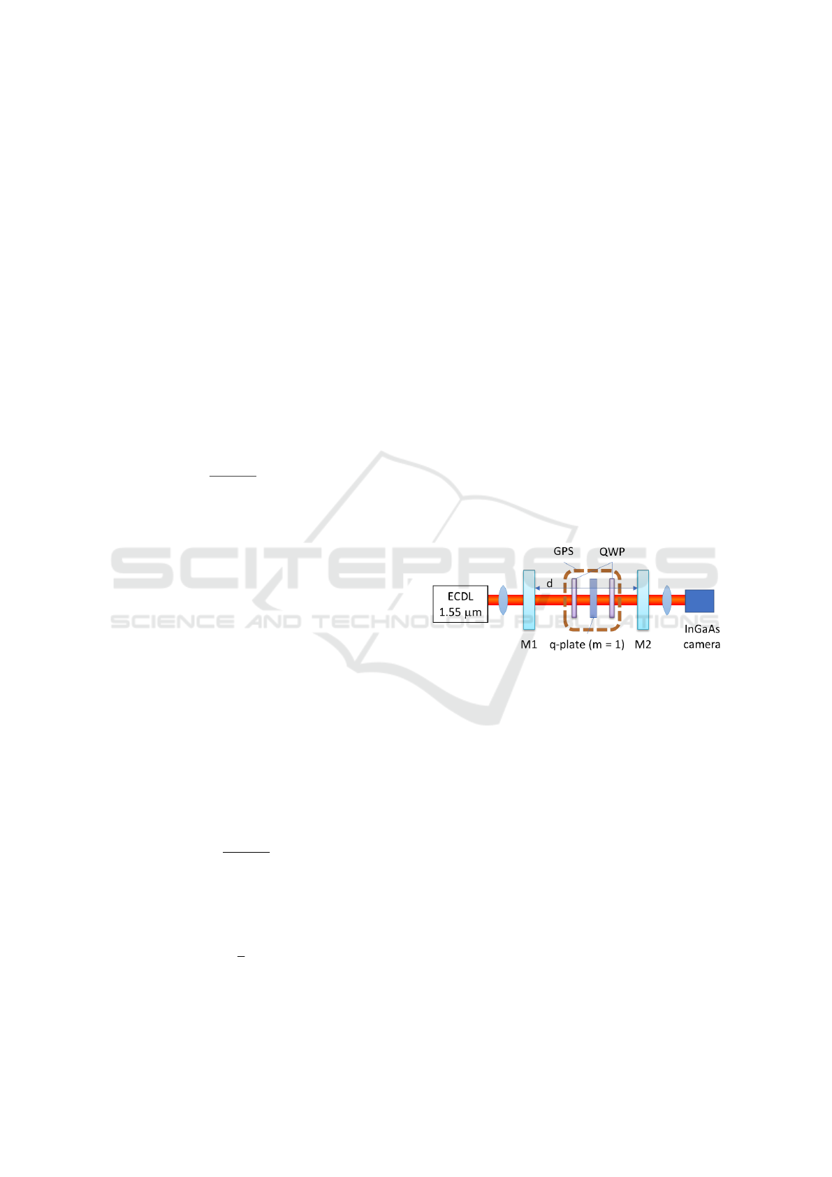
The experimental setup is depicted in Fig.1. A
beam from a single mode external cavity diode laser
(ECDL), wavelength of 1.55 µm, was incident to a
FP cavity. In the front of the FP cavity, the beam
was gradually diverged via a lens with a short focus-
ing length of 5 cm. In the presenting spectral drill, a
GPS consisting of two QWPs and a q-plate (Thorlabs,
WPV10L-1550, m=1) between them was allocated
within the cavity. Behind the cavity, the transmitted
beam pattern was measured by an InGaAs camera,
which has sensitivity for 1.55 µm. The spectral in-
formation can be measured without any mechanical
rotation of the HWP, whereas, in our prior works, we
have required a rotational stage for the HWP in order
to sweep the geometric phase.
Figure 1: Experimental setup. A geometric phase shifter
(GPS) using a q-plate is put within a FP cavity. GPS: ge-
ometric phase shifter, M1 and M2: cavity mirror, QWP:
quarter wave plate, ECDL: external cavity diode laser.
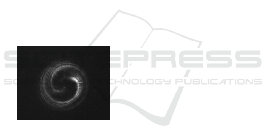
3.2 Results
A measured image under the condition of the cavity
length d of 3.2 cm is shown in Fig.2. A couple of
bright arms are observed in the image and the tra-
jectory of them draws spiral pattern from the center
to the outer part of the image. These bright curves
are respectively corresponding to the resonance of the
cavity. The number of bright arms of two is just
corresponding to our expected number of 2m since
the value of m in the q-plate was unity. The spiral
shape of the fringes is due to the slight longer cavity
length at the outer side from the center part consider-
ing a gradually diverging beam within the cavity. Al-
though it is not shown here, we have also confirmed
the arms gradually rotate with increasing the wave-
length or cavity length as expecting from Eq.(2).
PHOTOPTICS 2020 - 8th International Conference on Photonics, Optics and Laser Technology
98
Here, we estimate the frequency sensitivity of this
system when one obtains the frequency change of a
light source from the image. When d = 3.2 cm, the
free spectral range (FSR) of the cavity is derived as
4.7 GHz. The angle of view for a bright area on a arm
from the center position, denote with β, is obtained
as around 20 degrees. Consequently, the sensitivity
for the frequency change can be roughly estimated to
(FSR) · β/(2π/2m) = 0.5 GHz.
In the presenting system, the acquisition rate of a
spectral image was determined by the frame rate of
the InGaAs camera of 60 Hz. In our prior spectral
drill, we used an auto-rotational stage in order to ro-
tate a HWP. Comparing with the rotational speed of
the stage of 30 deg./sec., we considered that 720 times
faster acquisition rate was achieved.
We consider that this acquisition time is suffi-
ciently fast for feedback applications, for example
we are expecting the frequency locking of a single
mode laser within sub-GHz order frequency by per-
forming image analysis to every acquired image. For
more precise frequency locking, the improvement of
q-value of a cavity or a long cavity length will be nec-
essary.
Figure 2: A measured transmission image when cavity
length d = 3.2 cm.
4 CONCLUSIONS
In a spectral drill, we replaced a HWP on a rotational
stage with a q-plate and took the FP spectral image
using a camera for the high speed measurement. We
succeeded in 720 time faster acquisition of the spec-
tra than the prior spectral drill. It will open the new
methodology to control the laser frequency and its ap-
plications.
ACKNOWLEDGEMENTS
This work is partly supported by JSPS KAKEN
(JP18H01908, JP18K04967) and Tohoku University-
NICT matching fund 2019.
REFERENCES
Del’Haye, P., Arcizet, O., Gorodetsky, M. L., Holzwarth,
R., and Kippenberg, T. J. (2009). Frequency comb
assisted diode laser spectroscopy for measurement of
microcavity dispersion. Nature Photonics, 3(9):529–
533.
Huang, L., Chen, X., Muhlenbernd, H., Li, G., Bai, B.,
Tan, Q., Jin, G., Zentgraf, T., and Zhang, S. (2012).
Dispersionless phase discontinuities for controlling
light propagation. Nano Letters, 12(11):5750–5755.
PMID: 23062196.
Kawada, Y., Yasuda, T., and Takahashi, H. (2016). Carrier
envelope phase shifter for broadband terahertz pulses.
Opt. Lett., 41(5):986–989.
Marrucci, L. (2013). The q-plate and its future. Journal of
Nanophotonics, 7(1):1 – 5.
Ohno, S. (2018). Spectral drill: a geometrical phase
shifter within a fabry-p
´
erot cavity. OSA Continuum,
1(1):136–144.
Pancharatnam, S. (1956). Generalized theory of interfer-
ence, and its applications:part i. coherent pencils. Pro-
ceedings of the Indian Academy of Sciences - Section
A, 44(5):247–262.
Sanchez-Lopez, M. M., Abella, I., Puerto-Garcia, D.,
Davis, J. A., and Moreno, I. (2018). Spectral per-
formance of a zero-order liquid-crystal polymer com-
mercial q-plate for the generation of vector beams at
different wavelengths. Optics & Laser Technology,
106:168 – 176.
Yang, Y.-L., Ding, Z.-H., Wang, K., Wu, L., and Wu, L.
(2010). Full-field optical coherence tomography by
achromatic phase shifting with a rotating half-wave
plat. Journal of Optics, 12:035301.
High Speed Measurement in Spectral Drill using Q-plate and Camera
99
