
MultiSense: A Highly Reliable Wearable-free Human Fall Detection
Systems
Avishek Mukherjee
1
and Zhenghao Zhang
2
1
Dept. of Computer Science and Information Systems, Saginaw Valley University, U.S.A.
2
Computer Science Department, Florida State University, U.S.A.
Keywords:
Fall Detection, Sensors.
Abstract:
A reliable fall detection system has tremendous value to the well-being of seniors living alone. We design and
implement MultiSense, a novel fall detection system, which has the following desirable features. First, it does
not require the human to wear any device, therefore it is convenient to seniors. Second, it has been tested in
typical settings including living room and bathroom, and has shown very good accuracy. Third, it is built with
inexpensive components, with expected hardware cost around $150 to cover a typical room. Therefore, it has
a key advantage over the current commercial fall detection systems which all require the human to wear some
device, as well as over academic research prototypes which have various limitations such as lower accuracy.
The high accuracy is achieved mainly by combining senses from multiple types of sensors that complement
each other, which includes a motion sensor, a heat sensor, and a floor vibration sensor. As the activities that
are difficult to classify for some sensors are often not difficult for others, combining the strength of multiple
types of sensors brings the performance to a level that can meet the requirements in practice.
1 INTRODUCTION
A reliable fall detection system has tremendous value
to the well-being of seniors living alone. Studies show
that “one out of five falls causes a serious injury such
as broken bones or a head injury (CDC, 2013).” We
design and implement MultiSense, a novel fall detec-
tion system, which has the following main desirable
features:
• It is wearable-free, i.e., does not require the hu-
man to wear any device, therefore it is very con-
venient to seniors.
• It has shown excellent performance, e.g., it de-
tected all falls and raised no false alarms in a daily
use test, outperforming all existing systems to the
best of our knowledge.
• It is inexpensive. The hardware cost is expected
to be $150 or less to cover a typical room.
Currently, there are many companies offering fall
detection services with monthly charges around $40.
However, to the best of our knowledge, all commer-
cial systems, such as those listed as the top 10 fall de-
tection systems at (Preece, 2019), require the human
to wear some device, which can be inconvenient (Sku-
bic et al., 2016; Lipsitz et al., 2016). Many attempts
have been made in the academia on wearable-free fall
detection, including using depth camera (Mastorakis
and Makris, 2012; Planinc and Kampel, 2012; Ma
et al., 2014), vision (Debard et al., 2015; Anderson
et al., 2009), sound (Li et al., 2014; Li et al., 2012),
radar and RF signals (et al., 2015; Gadde et al., 2014;
Amin et al., 2015; Wang et al., 2017), floor vibration
(Alwan et al., 2006; Zigel et al., 2009), etc. However,
to date, the academia prototypes suffer various kinds
of limitations. For example, some may have low ac-
curacy in certain cases, some may have high cost, and
some may be intrusive to users with privacy concerns.
Therefore, academic wearable-free solutions are yet
to be adopted by the industry.
MultiSense achieves good performance mainly
by combining senses from multiple types of sensors,
which complement each other and enable simple and
robust rules to detect falls. The sensors include a mo-
tion sensor, a body heat sensor, and a floor vibration
sensor. For example, upon a fall, the motion sensor al-
ways reports a motion-to-stationary transition, i.e., a
motion period followed by a stationary period, corre-
sponding to the action during the fall and the inactiv-
ity after the fall (Sposaro and Tyson, 2009). However,
similar observations can be made during many other
events, such as a sit event. With the help of the vi-
Mukherjee, A. and Zhang, Z.
MultiSense: A Highly Reliable Wearable-free Human Fall Detection Systems.
DOI: 10.5220/0008957200290040
In Proceedings of the 9th International Conference on Sensor Networks (SENSORNETS 2020), pages 29-40
ISBN: 978-989-758-403-9; ISSN: 2184-4380
Copyright
c
2022 by SCITEPRESS – Science and Technology Publications, Lda. All rights reserved
29
bration sensor, however, the fall and sit event can be
very easily distinguished, because the latter produces
much smaller floor vibration than the former.
One of the most notable features of MultiSense
is that it does not depend on the availability of large
training data set. Instead, it makes decisions accord-
ing to simple logic and well-understood facts about
falls, such as a motion-to-stationary transition, the
floor vibration, which should hold for all falls. There-
fore, MultiSense is in sharp contrast with other fall
detection technologies, which typically involve ma-
chine learning and training data. This, we believe, is
an advantage for the particular problem of fall detec-
tion for seniors, because good training data may be
difficult to obtain, as the fall actions of seniors can
be very different from those of the healthy younger
persons who perform falls during the data collection
(Khan and Hoey, 2017; Kangas et al., 2012).
In the rest of the paper, Section 2 discusses related
work. Section 3 gives an overview of MultiSense.
Section 4 explains the details of MultiSense. Section
5 explains how MultiSense classifies activities other
than fall. Section 6 evaluates MultiSense. Section 7
compares MultiSense with other systems. Section 8
concludes the chapter.
2 RELATED WORK
The limitations of existing fall detection systems that
depend on wearable devices has led to a vast body of
academic research work on wearable-free fall detec-
tion. Ambient sensors that have been studied for fall
detection include vibration, sound, Wi-Fi, infrared,
Doppler radar, embedded sensors in the flooring ma-
terials, thermal, and certain combinations of the sen-
sors. Vibration sensors in combination with a micro-
phone was studied in (Alwan et al., 2006)(Zigel et al.,
2009); however, a number of issues in practice, such
as the difference in the intensity between the test ob-
ject and real human, as well as the effect of human
activities that may cause high floor vibration, such as
jumping and stomping, were not considered. Multi-
Sense on the other hand is evaluated with simulated
human falls and common human activities. Fall de-
tection with only sound signal was studied in (Li et al.,
2012; Li et al., 2014) based on signal processing tech-
niques to locate the source of the sound signal; how-
ever, it may generate 0.4 false alarms per hour based
on the reported performance. Wi-Fall (Wang et al.,
2017) is a system that detects human falls based on
Wi-Fi Channel State Information (CSI); however, the
reported accuracy is around 90%, which may not meet
the accuracy in some fall detection application sce-
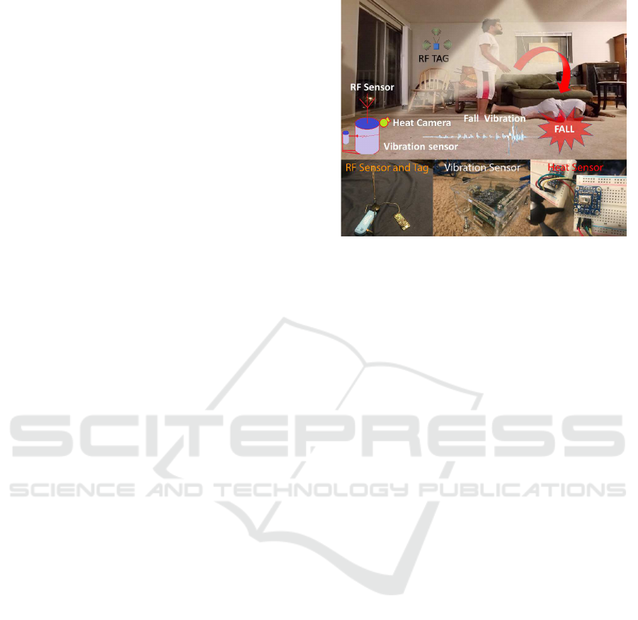
Figure 1: MultiSense system and sensors.
narios. MultiSense also has an RF module, but also
has other sensors for activity classification to achieve
high accuracy. Thermal data has been used for hu-
man tracking or activity recognition (Portmann et al.,
2014; Malpani et al., 2016). MultiSense is different
mainly because it also relies on other types of sensors,
while using simple logic for fall detection, without at-
tempting to solve typical image processing problems,
such as human shape reconstruction.
A recent multi-year testing in senior homes was
reported in (Skubic et al., 2016), which uses a com-
bination of Doppler radar, Kinect, and webcam for
fall detection. It was admitted that the solution is sus-
ceptible to sudden light changes and has difficulty de-
tecting falls occurring at such moments, such as a fall
occurred while opening the curtain. It is also more
expensive and may be less acceptable to users with
higher privacy concerns.
3 OVERVIEW OF MultiSense
This section gives an overview of MultiSense.
3.1 Features for Fall Detection
MultiSense is illustrated in Fig. 1. It is expected that
one MultiSense device will be needed in a room of
size around 16 square meters. Larger rooms will need
more devices proportionally. A device collects 3 types
of signals: the motion signal, the heat signal, and the
floor vibration signal. Roughly speaking, MultiSense
uses three simple facts as features that are likely to be
true for all falls:
• A motion-to-stationary transition in the motion
signal: A fall will begin with an motion period,
SENSORNETS 2020 - 9th International Conference on Sensor Networks
30
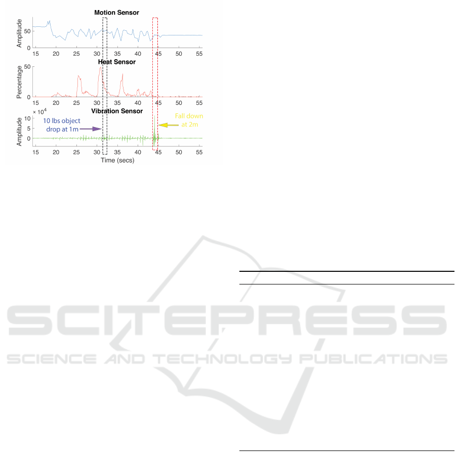
Figure 2: Typical signals.
followed by a stationary period when the person
lays on the floor.
• The heat sensor cannot detect the human after the
fall: the heat sensor measures temperatures. A
person in its view can be detected because the
body has higher temperatures than the environ-
ment. As the sensor points upwards, after the fall
when the person lays on the floor, the sensor can
detect no or very small area of the body.
• Large vibrations: A fall generates larger vibra-
tions than typical activities at the same spot.
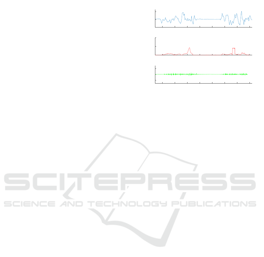
For example, Fig. 2 shows the output of the sen-
sors when a person walked into the room, got close to
the device at about 1 m, dropped a 10-pound object,
walked away, then fell at about 2 m to the device. It
can be seen that:
• The motion-to-stationary transition occurs in the
motion signal at around 44 sec, the time the fall
occurred.
• The heat sensor reading is close to 0 after the per-
son has fallen, therefore can determine the person
is not standing. Additionally, the heat sensor read-
ing is higher if the person is closer to the sensor,
and therefore can be used to estimate the distance
to the person.
• The vibration of the fall is much higher than walk-
ing steps and the object drop, even when the ob-
ject was 10 lbs and was dropped at a closer dis-
tance.
3.2 Outline of The Detection Algorithm
The detection algorithm is designed around the fea-
tures of falls explained earlier. It constantly checks
the motion sensor for the motion-to-stationary transi-
tion. Once a transition is found, the algorithm esti-
mates the distance of the person to the device with the
heat sensor reading. Currently, the possible distances
are: within 0.5 m, within 1 m, in the view, or not in
the view. The distance is used to select a threshold of
the vibration; higher thresholds are used for smaller
distances. If the vibration reading is higher than the
selected threshold and the heat sensor does not de-
tect the person after the transition, the algorithm de-
clares a fall. If the vibration reading is higher than the
threshold but the heat sensor still detects a standing
person after the transition, the algorithm waits for 30
seconds, and still declares a fall is no movement has
been detected in the 30 seconds. This is because if it is
an actual fall, the heat sensor has likely detected some
heat source but not an actual person. However, after
the fall, the person will likely be stationary; therefore
the algorithm can still detect the fall after 30 seconds.
If it is not a fall but some activity such as jumping or
stomping, it is extremely unlikely that the person will
remain stationary for 30 seconds. It is clear that the
algorithm should detect falls; in Section 5, it is ex-
plained why it will not misclassify non-fall activities
as falls.
Algorithm 1: MultiSense Fall Detection Algorithm.
1: if the motion sensor detects a motion-to-
stationary transition then
2: if the vibration reading is larger than a thresh-
old based on the estimated distance then
3: if the heat sensor does not detect the human
to be standing after the transition then
4: Declare a Fall
5: else
6: Declare Fall if no movement is detected
by the motion sensor in the next 30 sec-
onds
7: end if
8: end if
9: end if
3.3 Installation and Cost Breakdown
The motion signal is based on the changes of the elec-
tromagnetic field due to human movements. It is col-
lected by an RF receiver inside the device, which
monitors the RF signal emitted by small ultra-low
power RF transmitters placed in the same room. For
each RF receiver, 1-2 transmitters are needed. The
heat sensor and the vibration sensor are inside the de-
vice. The heat sensor detects humans based on the
temperature, and should be positioned at least half
a meter above the floor, pointing upwards at an an-
gle, with no obstacles within one meter to block its
view. It is also suggested to keep the heat sensor away
from heat sources, such as a stove or the air condi-
MultiSense: A Highly Reliable Wearable-free Human Fall Detection Systems
31

tioner. The vibration sensor should have contact with
the floor to monitor vibration. The overall cost is es-
timated at $150 based on the parts used in the pro-
totype, including: $40 for the processing unit which
can be a Raspberry Pi, $30 for the RF unit, $40 for
the heat sensor, $15 for the vibration sensor, and $25
for other circuits.
3.4 Discussions on More than One
Person
MultiSense is designed for seniors living alone, and
the algorithm assumes that there is only one person
in the room. When there are more than one person,
if one person falls, the other can provide help. As
a result, even if MultiSense fails to detect an actual
fall, it will not be an issue in practice. The other
type of error, i.e., misclassifying non-fall activities
as falls, is less critical but still annoying. However,
note that: 1) if the second person is moving, the
motion-to-stationary transition cannot be observed, 2)
if the second person is in the view of the heat sen-
sor, MultiSense should usually find a person standing.
Therefore, the second person can help causing errors,
only when the person stays motionless and out of the
view of the heat sensor, but somehow helps generating
some large vibration, which is an unlikely scenario.
4 DETAILS OF MultiSense
In this section, we explain our solutions to many prac-
tical challenges in MultiSense, such as determining
the existence of the motion, estimating the human dis-
tance even in the presence of a heat source, etc.
4.1 Motion Detection (MD) Module
The MD module is based on the RF signal. It con-
sists of a receiver and simple transmitters called tags
operating in the 433 MHz band, where the receiver
is currently implemented with inexpensive low band-
width software defined radios (RFS, ), and the tags
are implemented with programmable wireless mod-
ules (RFT, ). Basically, the tags periodically transmit
their IDs and the receiver demodulates the RF signal
and considers there is motion if the fluctuation of the
wireless channel is above a level, and otherwise sta-
tionary.
4.1.1 Implementation
In practice, the main challenge is to extend the bat-
tery life of the tags, because at least some of them
may have to be placed in locations with no power out-
let, such as a shower room. Therefore, an ultra-low
power design based on pulse interval modulation is
adopted for the tags, which has been used in some ac-
tive RFIDs, allowing the RFID to last on a single coin
cell battery for 2-3 years (RFC, ). To be more specific,
in the current design, a tag transmits its ID on average
every 200 ms, with some random offset every time to
avoid consistently colliding with another tag. The tag
ID is basically a burst of 10 pulses, where each pulse
is very short for about 40 µs. The tag identity is rep-
resented by the intervals between the pulses, called
the signature, which are preselected pseudo random
numbers, ranging from 1.5 to 2.5 ms. For example,
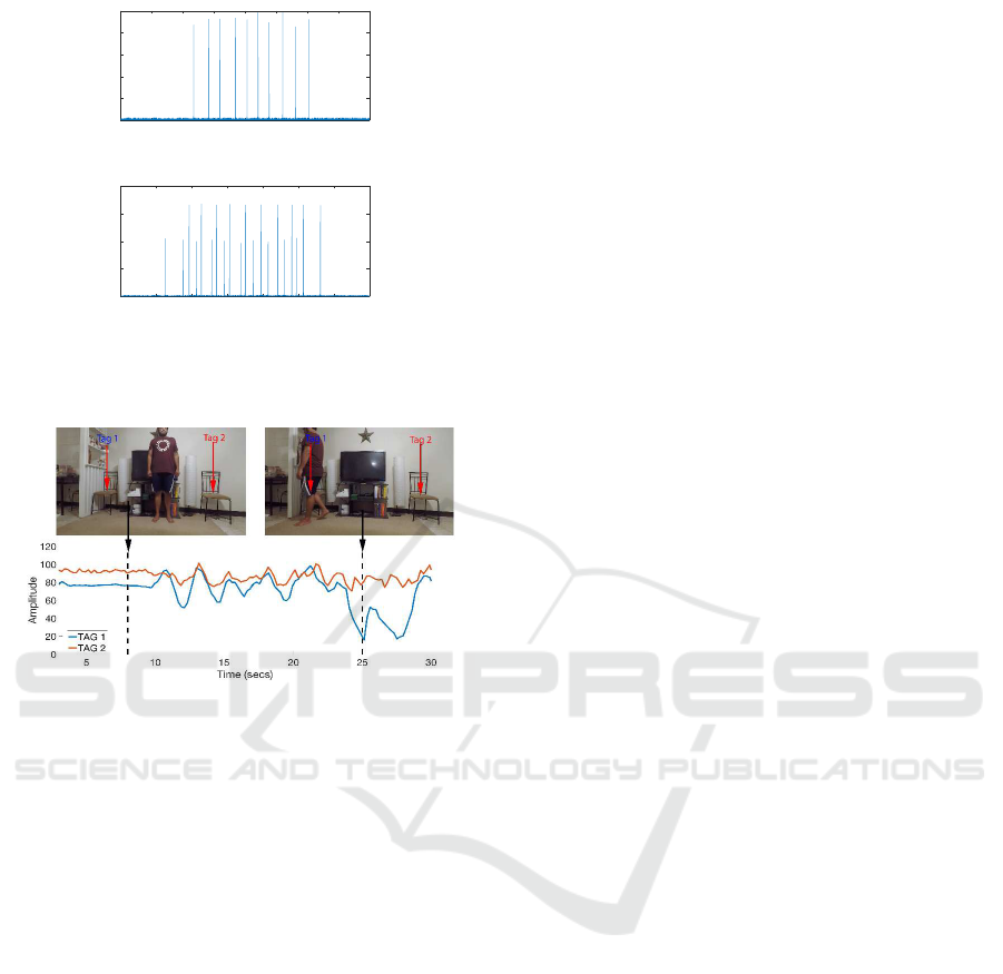
Fig. 3(a) shows the burst from one tag. With the pulse
interval modulation, the tag is idle for most of the
times, except when it needs to transmit its ID, which
is less than 0.2% of the time with the current design.
As there could be multiple tags in the vicinity, the
receiver adopts a simple algorithm to separate the sig-
nals from the tags, which can also tolerate some low
level of collision, where a collision occurs when the
pluses from two tags overlaps in time. For example,
Fig. 3(b) shows the bursts from two tags. The algo-
rithm assumes that the number of tags is small and
the tag signatures are known to the receiver, which
are true in the current implementation. The receiver
scans the signal for pulses. When it finds a pulse, it
assumes the pulse to be the first pulse of a burst of
some tag and starts checking the tags. For a partic-
ular tag, the receiver aligns the first pulse of the tag
with the identified pulse, and checks if the matching
condition is satisfied, i.e., at least 9 pulses are found
at the time the tag is supposed to transmit pulses ac-
cording to its signature. The receiver checks all tags
and outputs any tag that satisfies the matching condi-
tion. The complexity is further reduced, i.e., not all
detected pulses are considered as the first pulse and
trigger the check, by exploiting one feature in the cur-
rent design. That is, the first and the last pulses of a
burst are separated by a constant time. Therefore, a
pulse is considered a first pulse only if a pulse also
appears at exactly the time when the last pulse is sup-
posed to appear.
4.1.2 Extracting the Wireless Channel Condition
The condition of the wireless channel from a tag to a
receiver can be easily learned from the amplitude of
the pulses. It was found that the measured amplitude
is stationary when there is no human movement; how-
ever, with human movement, which changes the elec-
tromagnetic field, the measured amplitude will show
significant variations. Therefore, MultiSense uses the
amplitude of the pulses as the decision variable to es-
SENSORNETS 2020 - 9th International Conference on Sensor Networks
32
0 0.5 1 1.5 2 2.5 3 3.5 4
Time (usecs)
×10
4
0
20
40
60
80
100
Amplitude
(a)
0.5 1 1.5 2 2.5 3 3.5 4
Time (usecs)
×10
4
0
50
100
150
200
Amplitude
(b)
Figure 3: Bursts from tags.
Figure 4: Motion sensor reading examples.
timate whether or not the person is moving. An ex-
ample is shown in Fig. 4, where the amplitude of 2
tags are shown. The person was stationary up to 10
seconds, and started moving afterwards. Correspond-
ingly, the tags signals were stationary in the first 10
seconds and started to fluctuate in various ways after-
wards. To determine whether the person is stationary
or moving, MultiSense calculates the standard devi-
ation of the pulse amplitudes, and considers human
movement detected if the standard deviation is more
than 3 times the standard deviation of the signal when
the person is not present. As a receiver may receive
the signal from multiple tags, the tag with the largest
fluctuation is used, because motion exists if fluctu-
ation can be detected by any tag. The fluctuation
threshold is calibrated at regular intervals when the
person is determined not in the room.
4.1.3 Discussion
The RF-base motion detection is more sensitive to
movements near the tag or the receiver. One con-
cern is that after a fall near the tag or the receiver,
the person may make some small movements, causing
the system to believe there is still motion. However,
in practice, the tags should be mounted at a certain
height above the floor, and is therefore naturally a cer-
tain distance away from the person after the fall as the
person is on the floor. Further testing was conducted
to uncover the response of the system to human small
movements at 25 cm from the receiver, which show
that micro movements made by a person after a fall
does not affect the receiver enough to falsely classify
as in motion. Another concern was that human move-
ment in other rooms; however it was also found that
the fluctuation is also too small to cause any error.
4.2 Heat Sensing (HS) Module
The Heat Sensing (HS) module is implemented with
Adafruit AMG8833 IR Thermal Camera due to its
low cost, which has 64 pixels, each spanning angle of
roughly 7.5 degrees (hea, ). The heat sensor outputs
the temperature values based on the infrared signals it
receives on each pixel. With proper calibration, it can
be used to both estimate the distance of the person to
the device, as well as determining whether or not the
person is standing.
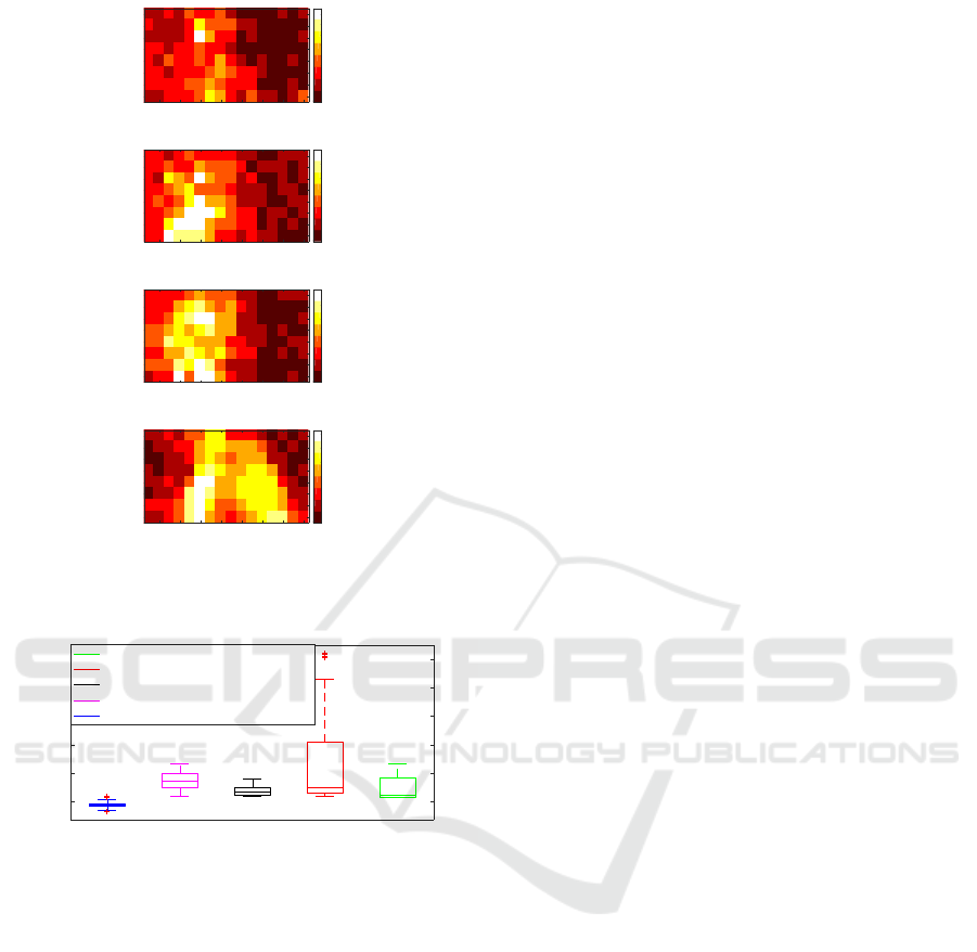
4.2.1 Estimation of Human Distance
The human distance can be estimated, because the
closer the person is, the more pixels in the sensor re-
port high values. For example, Fig. 5 shows the heat
maps of different distances. To estimate the distance,
the algorithm selects a lower and upper temperature
threshold, and considers any pixel within this range
to be occupied by a human body, and refers to them
as human pixels. The details for establishing these
thresholds are discussed in Section 4.2.4. The algo-
rithm uses the percentage of human pixels as the de-
cision variable. Based on empirical data, when the
percentage are at least 3%, 25%, and 50%, the dis-
tance are within the view, 1 meter, and half meter,
respectively.
4.2.2 Standing Human Detection
The heat sensor can determine if a person is stand-
ing or not, because after the person has fallen down,
the person should be outside the view of the heat sen-
sor, which points upwards. However, it could happen
that the sensor can still detect the person, for exam-
ple, when the person falls very close to the sensor, or
when the person lands on the hip in a sitting pose.
Nevertheless, even in these cases, the person should
only appear in the bottom part of the sensor. There-
fore, the algorithm looks for human pixels only in the
inspected area, which is the top 50% of the sensor
if the estimated human distance is 0.5 meters or less,
MultiSense: A Highly Reliable Wearable-free Human Fall Detection Systems
33
2 4 6 8 10 12 14 16
1
2
3
4
5
6
7
8
24
24.5
25
25.5
26
26.5
27
27.5
28
(a)
2 4 6 8 10 12 14 16
1
2
3
4
5
6
7
8
23
24
25
26
27
28
29
(b)
2 4 6 8 10 12 14 16
1
2
3
4
5
6
7
8
23
24
25
26
27
28
29
(c)
2 4 6 8 10 12 14 16
1
2
3
4
5
6
7
8
25
26
27
28
29
30
31
(d)
Figure 5: Heat sensor raw reading. (a) Not in the view. (b)
Inside the view. (c) Within 1 m. (d) Within 0.5 m.
Sources of heat
25
30
35
40
45
50
Temperature
Hot Water Pot at 2m
Hot Water Pot at 1m
Human with multiple layers of clothes
Human at 1m
Ambient Room Temperature
Figure 6: Temperature readings on the heat sensor.
and the top 75% of the sensor for all other distances.
The algorithm checks the bottom row of the inspected
area for human pixels. As a standing person should al-
ways appear on this row, the algorithm considers the
person to be standing if at least 2 human pixels are
found in this row. The bottom row may be redefined
if heat sources are present, which is explained in Sec-
tion 4.2.3.
4.2.3 Presence of Heat Sources
Heat sources, like a fireplace or a cup of hot water,
when introduced into the environment, may some-
times be confused as human pixels. Fig. 6 shows the
temperature readings of some heat sources compared
to the human body temperature. It was found that:
• Smaller heat sources, like a cup of hot tea, when
placed near the sensor, some areas surrounding
the heat source can sometimes be classified as hu-
man pixels. Fortunately, when placed at distances
further than 1 m, they are much smaller than the
area mapped to a single pixel and usually does not
register anything significantly higher than the am-
bient room temperature.
• Larger heat sources, like a fireplace or a large hot
pot of water, when placed near the sensor, the
outer edges of the heat source may have a lower
temperature than the middle, and may fall within
the thresholds of a human pixel. When placed fur-
ther away, the decay in infrared signal strength
causes the sensor to register a temperature that
is lower than the actual temperature of the heat
source, and also may be classified as human pix-
els.
There are two main issues that arise when heat
sources are introduced into the environment. First,
the human distance estimation algorithm may mistake
some of the heat source pixels as human pixels. This
leads MultiSense to believe that the person is closer
than the person actually is, and apply a larger vibra-
tion threshold. Second, the standing human detection
is also affected, as MultiSense might detect a standing
person if a heat source present in the top part of the
sensor.
To overcome this, a simple algorithm is run first
to remove heat source pixels before running the dis-
tance and standing estimation modules, based on the
fact the most heat sources will lead to some very hot
pixels. To elaborate, the algorithm first checks if any
pixel exceeds the upper human temperature threshold.
If such pixels are found, the algorithm discards them,
as well as any adjacent pixels, as these may also be
affected by the heat source. The higher the tempera-
ture reading, the more adjacent pixels are removed. In
the current implementation, if a pixel has a reading of
more than 40, then pixels with a distance of 3 or less
are removed; otherwise, pixels with a distance 2 are
removed. After some pixels are removed, the bottom
row needed in standing human detection is redefined
as the lowest pixel that has not been removed in each
column of the inspected area. If more than 50% of
the pixels are estimated to be some heat source, the
heat sensor data is rendered useless, and the situation
is treated the same as when the human is not in the
view of the sensor.
4.2.4 Threshold Values
To establish the lower threshold, a simple clustering
algorithm is used to cluster the sensor readings in
to two clusters. The cluster with lower values is as-
SENSORNETS 2020 - 9th International Conference on Sensor Networks
34
sumed to be the ambient temperature, and the lower
threshold is the mean temperature of this cluster plus
8 times the standard deviation of all temperature read-
ings in this cluster. The upper threshold is calibrated
only once per sensor, by recording the maximum tem-
perature reported by the heat sensor pixels when the
human is standing close to the sensor, and remains
constant thereafter. One may concern that the human
body temperature may go lower if the human is wear-
ing multiple layers of clothing as shown in Fig. 6.
However, this will usually only happen in colder tem-
peratures, when the overall ambient temperature of
the room is also lower, and so it will still be higher
than the lower threshold. The heat sensor is calibrated
at regular intervals as long as no movement is detected
in the room, i.e. the human may be present in the
room, but is not mobile.
4.3 Floor Vibration Detection (FVD)
Module
The Floor Vibration Detection (FVD) module reports
the vibration of the floor. Currently, it is implemented
with RaspberryShake (vib, ), a seismograph device
for Raspberry Pi, which constantly reports the vibra-
tion reading every 20 ms that reflects the amount of
vibration felt by the sensor. Typically, the maximum
observed vibration reading reflects the intensity of the
vibration, and is therefore used as the decision vari-
able. The vibration reading is compared with cer-
tain threshold values to help determine if a fall has
occurred. Clearly, even for exactly the same person
or object falling in exactly the same manner, many
factors can lead to changes in the reading, including,
the distance to the sensor, the floor type, i.e., concrete
or wood, etc. Therefore, the threshold values must
be learned for each deployment, which fortunately
can be achieved by a simple process. That is, dur-
ing installation of the system, simulated falling events
should be created in the room on a number of calibra-
tion locations to record the signal amplitude to deter-
mine the threshold value at variant distances to the
device, where the number of distances depends on the
room size.
5 COPING WITH NON-FALL
ACTIVITIES
In this section, we explain how the internal logic of
MultiSense copes with typical non-fall activities and
makes the correct decisions except for only some rare
activities.
20 25 30 35 40 45 50 55
Time (secs)
-2
0
2
Amplitude
×10
4
Vibration Sensor
20 25 30 35 40 45 50 55
0
50
100
Percentage
Heat Sensor
20 25 30 35 40 45 50 55
0
50
100
Amplitude
Motion Sensor
Figure 7: Sitting down and standing up.
5.1 Everyday Activities
Everyday activities include: 1) entering the room, 2)
walking in the room, possibly making a stop in the
middle, 3) sitting down for a while, 4) getting up, and
5) leaving the room, possibly slamming the door on
the way out. In such activities, the motion sensor may
detect a motion-to-stationary transition, for example,
when the person sits down, leaves the room, or makes
a stop during walking. Also, the heat sensor may be
blocked, for example, by the chair. However, Multi-
Sense can easily determine no fall has occurred, be-
cause none of such activities will generate large vi-
brations exceeding the vibration threshold. Note that
even for door slamming, as its vibration is mainly on
the walls, while the vibration sensor is on the floor,
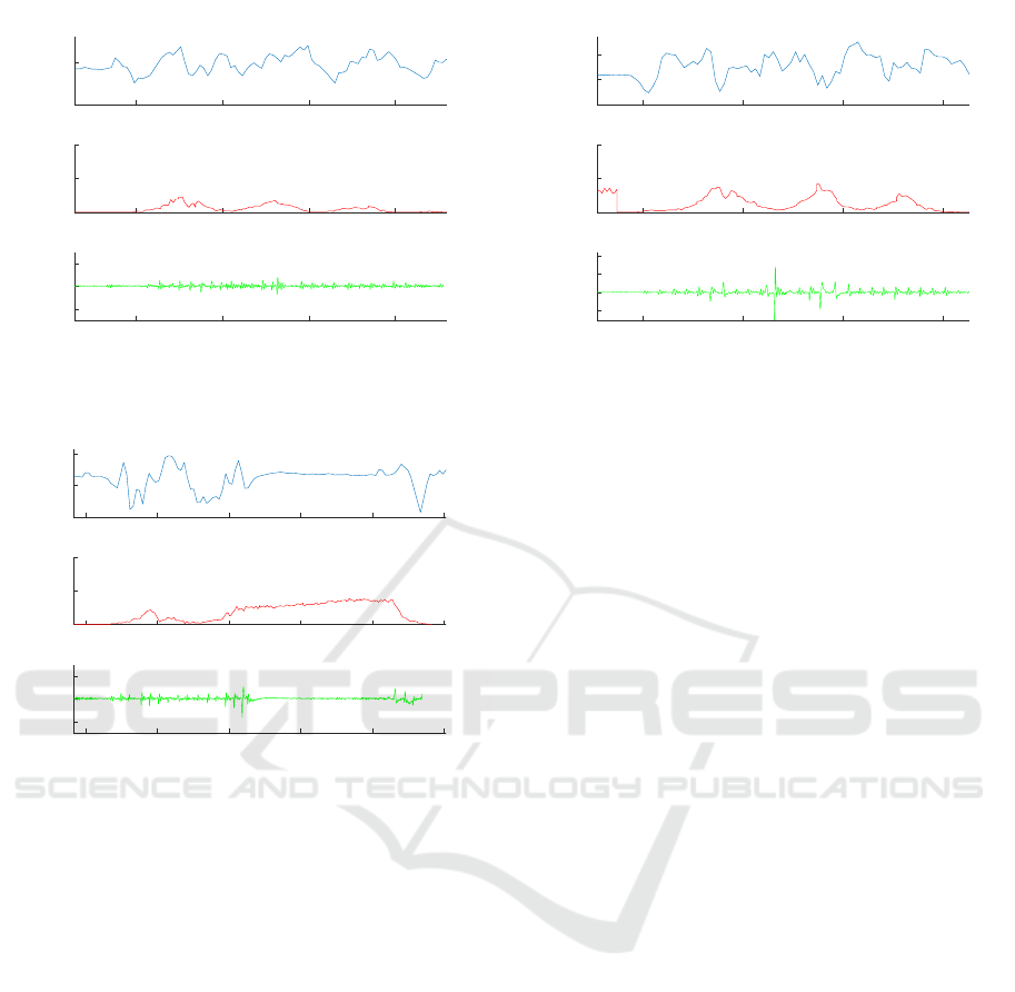
the vibration reading is low. An example is shown in
Fig. 7, where the person sat down at around 32 sec,
after which the heat sensor was blocked, then got up
at around 43 sec. It can be seen that the vibration sen-
sor readings are small.
5.2 Object Drop
Dropping an object may also occur in everyday lives,
although it should be much less often than other ev-
eryday activities discussed earlier. It may need a sepa-
rate discussion, because it will lead to larger vibration
sensor readings.
5.2.1 Normal Object Drop
In a typical scenario, after a person drops an ob-
ject, the person will bend over to pick it up. In
this case, the motion sensor will not find a motion-
to-stationary transition at the time when large vibra-
tion was recorded, therefore no fall will be declared.
Fig. 8 shows an example, where the person dropped
MultiSense: A Highly Reliable Wearable-free Human Fall Detection Systems
35
15 20 25 30
Time (secs)
-2
0
2
Amplitude
×10
4
Vibration Sensor
15 20 25 30
0
50
100
Percentage
Heat Sensor
15 20 25 30
0
50
Amplitude
Motion Sensor
Figure 8: Normal object drop.
15 20 25 30 35 40
Time (secs)
-2
0
2
Amplitude
×10
4
Vibration Sensor
15 20 25 30 35 40
0
50
100
Percentage
Heat Sensor
15 20 25 30 35 40
0
50
100
Amplitude
Motion Sensor
Figure 9: Freeze large object drop within 1 meter.
a 20-lb object while walking, then picked it up, then
continued waling. It can be seen that no motion-to-
stationary transition occurred.
5.2.2 Freeze Object Drop
In some very rare cases, a person may drop an object
while walking, and then stop walking, therefore the
word “freeze.” In this case, the motion sensor will
detect a motion-to-stationary transition. Fortunately,
it was found that even 20-lb objects will not cause as
large a vibration as a human fall at the same distance
to the sensor. As a result, MultiSense will still not
declare a fall, because it can select the correct vibra-
tion threshold, which will be higher than the vibration
cased by the drop. In addition, in many cases, the per-
son is still within the view of the heat sensor after the
drop, further preventing a fall to be declared, as long
as the freezing period is not longer than 30 sec. An
example is shown in Fig. 9, where a 20-lb object was
dropped at around 26 sec.
20 25 30 35
Time (secs)
-2
0
2
4
Amplitude
×10
4
Vibration Sensor
20 25 30 35
0
50
100
Percentage
Heat Sensor
20 25 30 35
0
50
100
Amplitude
Motion Sensor
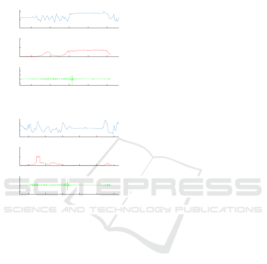
Figure 10: Normal jump.
5.3 Jumping and Hard Stomping
It could happen that a person jumps or stomps hard,
although it could be less often for seniors. These ac-
tivities are most challenging to a fall detection system,
because they may generate the motion-to-stationary
transition, as well as large vibrations. Note that the
stomping has to be hard because soft stomping will
not generate large vibrations.
5.3.1 Normal Jumping and Hard Stomping
In a normal scenario, a person, while walking, may
jump or stomp, and then continue walking. Multi-
Sensor will not declare a fall, because the person is
moving continuously and there will be no motion-to-
stationary transition. An example is shown in Fig.
10, where the jump occurs at around 26 sec, but the
motion sensor records large variations throughout the
period.
5.3.2 Close Freeze Jumping or Hard Stomping
To further challenge MultiSense, consider a scenario
where the person is initially walking, then jumps or
stomps hard at a location that is still in the view of
the heat sensor, and then stands still. MultiSense will
not consider it a fall, because although a motion-to-
stationary transition does occur and the vibration sen-
sor will likely register a large vibration value, the heat
sensor should still detect the person as standing. An
example is shown in Fig. 11, where the person jumps
at around 30 sec, however the heat sensor detects the
person to be standing. MultiSense may declare a fall,
only if the person stays still after the jump or stomp
for over 30 seconds, which can be argued to be an
extremely unlikely scenario.
SENSORNETS 2020 - 9th International Conference on Sensor Networks
36
20 25 30 35 40
Time (secs)
-2
0
2
4
Amplitude
×10
4
Vibration Sensor
20 25 30 35 40
0
50
100
Percentage
Heat Sensor
20 25 30 35 40
0
50
100
Amplitude
Motion Sensor
Figure 11: Freeze jumping at close distances.
20 25 30 35 40 45
Time (secs)
-2
0
2
Amplitude
×10
4
Vibration Sensor
20 25 30 35 40 45
0
50
100
Percentage
Heat Sensor
20 25 30 35 40 45
0
50
100
Amplitude
Motion Sensor
Figure 12: Freeze jumping far away.
5.3.3 Far Freeze Jumping or Hard Stomping
A misclassification may occur when a person jumps
or stomps hard at a location outside the view of the
heat sensor, and then stands still. Note that such activ-
ities should be very rare for seniors. The motion sen-
sor will detect a motion-to-stationary transition. The
heat sensor will not detect the person; therefore, Mul-
tiSense has to apply the smallest vibration threshold.
As the vibration caused by a jump or a hard stomp
is comparable to those caused by a fall, the vibration
threshold may be exceeded. An example is shown in
Fig. 12, where the jump occurred at around 31 sec,
and the signal is similar to that from a fall. To avoid
misclassification, the device should be placed such
that the person is in the view of the heat sensor as
much as possible.
6 EVALUATION
MultiSense is evaluated in realistic environments in-
cluding a living room and a bathroom. The evaluation
includes:
• False Negative (FN) stress tests: a person falls in
different manners and locations, to check if Mul-
tiSense can correctly detect the falls.
• False Positive (FP) stress tests: the activities listed
in Section 5 are repeated for a number of times, to
check if MultiSense can correctly determine them
not to be falls.
• Daily use tests: the system runs for 24 hours in
a room with the person conducting normal activ-
ities, to check if the system makes any incorrect
alarms of falls.
Overall, MultiSense reports excellent performance,
with no errors in the FN stress tests and the daily
use tests, and errors in the FP stress tests only for 2
activities that should occur very rarely for the seniors.
6.1 False Negative Stress Tests
The FN stress tests were conducted in a typical liv-
ing room and a bathroom, and in the presence of a
heat source. It was found that MultiSense correctly
detected all falls.
6.1.1 Living Room Tests
A total of 100 experiments were conducted inside a
typical living room of size around 16 square meters
with carpet on concrete floor, as shown in the left of
Fig. 13. Each experiment starts with a 5-second cali-
bration period, after which the test subject starts some
normal activities, such as walking, and then simulates
a fall at a random time. The types of falls include hard
falls, soft falls, forward falls, and backward falls, and
occurred at various distances to the device. The lo-
cations of some of the falls are shown in the right of
Fig. 13. To be more exact, in 37%, 53%, and 10%
of the tests, the heat sensor could determine that the
person at a distance of 1 meter or less, more than 1 m
but still in the view, and not in the view, respectively.
Fig. 14 and Fig. 15 explains the main reasons why
MultiSense was able to detect all falls correctly. Note
that the first check of any potential fall is the motion-
to-stationary transition. Fig. 14 is a scatter plot, where
the x and y coordinates of a point are the threshold for
detecting motion and the motion sensor reading, re-
spectively. The readings before and after the fall are
shown in different colors. It can be seen that the data
before fall are all above the diagonal line, while the
MultiSense: A Highly Reliable Wearable-free Human Fall Detection Systems
37
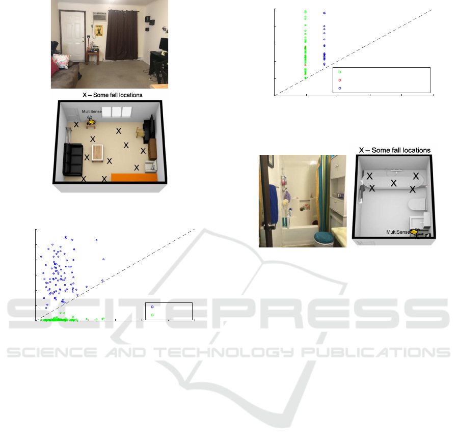
Figure 13: The living room in the test.
0 5 10 15 20 25 30
Motion Sensor Threshold
0
5
10
15
20
25
30
Standard Deviation (Measured)
Before Fall
After Fall
Figure 14: Motion-to-stationary transition detection in the
living room.
data after fall are all below the line, which suggests
that the motion was detected before the fall and not
detected after the fall. The threshold values appear in
a fairly large range, which is caused by a defect in the
current tag implementation, as it sometimes transmits
pulses at different magnitudes. Fig. 15 is also a scatter
plot, where the x and y coordinates of a point are the
selected vibration threshold and the vibration reading
of the fall, respectively. It can be seen that the vibra-
tion threshold was exceeded in all cases shown in the
figure, suggesting that MultiSense indeed picked the
right threshold depending on the distances of the fall
to the device. It may need to be mentioned that for
the living room, based on its size, 3 vibration thresh-
old values were learned. Therefore, the points would
appear in three vertical lines. Only two lines are in
the figure, because falls very close to the device lead
to very large vibration readings and have to be cut off
to show details in other cases.
1 1.5 2 2.5 3 3.5
Vibration Threshold
×10
4
1
1.5
2
2.5
3
3.5
Maximum Vibration
×10
4
Outside view of heat sensor
Inside view of heat sensor
Within 1m of heat sensor
Figure 15: Vibration sensor reading and the threshold in the
living room.
Figure 16: The bathroom in the test.
6.1.2 Bathroom Tests
A total of 50 experiments were conducted inside a
bathroom shown in the left of Fig. 16, with similar
calibration period at the beginning, and various kinds
of falls at random times afterwards. Some of the fall
locations are shown in the right of Fig. 16. As the
bathroom is small, falls were simulated in the bathtub,
noting that falls outside the bathtub are equivalent to
falls near the device in the living room. In half of the
cases, the shower curtain was open, and the other half
closed, which simulate falls occurred when the per-
son was trying to leave the bathtub, and falls inside
the bathtub, respectively. Note that the heat sensor
is outside the bathtub, and cannot detect the person
when the shower curtain is closed.
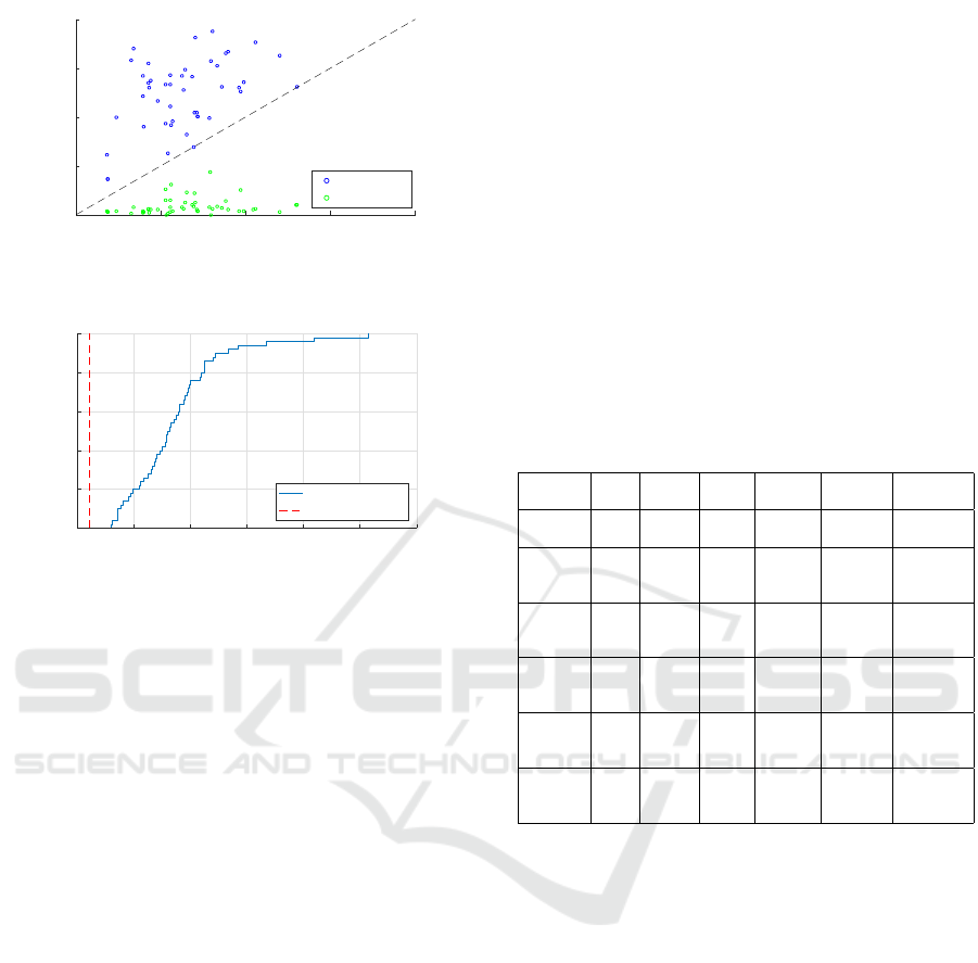
Fig. 17 and Fig. 18 explains the main reasons
why MultiSense was able to detected all falls cor-
rectly. Fig. 17 is a scatter plot, confirming that all
fall events lead to detected motion-to-stationary tran-
sitions. Fig. 18 shows the Cumulative Density Func-
tion (CDF) plot of the vibration reading of the falls,
in which the vertical line is the threshold. Note that
only one threshold was used because the bathroom is
small. It can be seen that the vibration threshold was
exceeded in all cases.
SENSORNETS 2020 - 9th International Conference on Sensor Networks
38
0 5 10 15 20
Motion Sensor Threshold
0
5
10
15
20
Standard Deviation (Measured)
Before Fall
After Fall
Figure 17: Motion-to-stationary transition detection in the
bathroom.
2 3 4 5 6 7 8
Maximum Vibration
×10
4
0
0.2
0.4
0.6
0.8
1
Fraction
Recorded Value
Threshold
Figure 18: Vibration sensor reading and the threshold in the
bathroom.
6.1.3 Heat Source Tests
MultiSense was also tested with heat sources placed
close to the sensor. A total of 8 tests were conducted
with a person simulating a fall next to the heat source,
as well as behind the heat source. Additionally, a
larger heat source was used in 2 tests, such that the
heat source covered more than half of the sensor area.
As mentioned in Section 4, this will cause MultiSense
to ignore the heat sensor data, and rely only on the
motion and the vibration sensors. Still, MultiSense
detected the falls in all cases.
6.2 False Positive Stress Test
The activities listed in Section 5 also tested, and, as
expected, MultiSense did not declare any falls, except
for 80% and 20% cases for Far Freeze Jump and Far
Freeze Hard Stomp, respectively. However, as ex-
plained earlier, these two activities are likely to be
very rare for seniors.
6.3 Daily Use Test
MultiSense was also tested over a 24-hour period in
a living room. During the test period, 7 human falls
were simulated at random times, and MultiSense de-
tected all falls correctly. In addition, usual day-to-day
activities, such as leaving or entering the room, sit-
ting down, standing up, walking around, etc., were
conducted, and MultiSense did not report any falls for
such activities.
7 COMPARISON
Table 1 is a comparison between MultiSense and
some existing wearable-free fall detection systems,
where the performance numbers are those reported in
the papers and the costs are estimated based on the
cost of sensors used in MultiSense. It can be seen that
MuliSense has superior performance, and is not sus-
ceptible to privacy breaches or the imperfection of the
training data, while keeping the cost modest.
Table 1: Comparison with other systems.
Name FN FP Cost Privacy Rely on Bathroom
issue Training test
Multi- 0% 0 per $150 No No Yes
Sense hour
(Wang) 2% 12% $80 No Yes No
et al.,
2017
(Skubic) 2% 1 per $140 Yes Yes No
et al., month
2016
(Zigel 3% 1.4% $60 No Yes No
et al.,
2009)
(Li) 2% 0.4 $140 No No No
et al., per
2014 hour
(Debard 24% 59% $200 Yes Yes No
et al.,
2015)
8 CONCLUSIONS
We propose MultiSense, a novel fall detection sys-
tem, which is wearable-free and reasonably inexpen-
sive. MultiSense combines a motion sensor, a heat
sensor and a vibration sensor to detect human falls.
Multisense does not require extensive training data
and is not invasive to privacy. Our evaluation showed
that MultiSense was able to detect human falls ac-
curately each time in the False Negative stress tests,
and did not make any error in a daily use test. Er-
rors were only found in two types of unusual activi-
ties in the False Positive stress tests, i.e., keeping still
after jumping or hard stomping while staying out of
the view of the heat sensor, which are unlikely to oc-
cur often in the daily life of seniors. Therefore, we
believe MultiSense can be used to accurately detect
human falls and can be extremely helpful to seniors
living alone. Our future work includes more extensive
MultiSense: A Highly Reliable Wearable-free Human Fall Detection Systems
39

tests of the system, as well as enhancing MultiSense
with even more sensors.
REFERENCES
Adafruit AMG8833 IR Thermal Camera Breakout.
https://www.adafruit.com/product/3538.
Adafruit Feather 32u4 with RFM69HCW Packet Radio -
433MHz. https://www.adafruit.com/product/3077.
NooElec NESDR Mini 2 SDR.
https://www.nooelec.com/store/ sdr/ sdr-
receivers/nesdr-mini2-rtl2832u-r820t2.html.
Raspberry Shake Original Pi-Full Kit.
https://shop.raspberryshake.org /product/magnitude-
9/.
RF Code. http://www.rfcode.com/.
Alwan, M., Rajendran, P., Kell, S., Mack, D., Dalal, S.,
Wolfe, M., and Felder, R. (2006). A Smart and Passive
Floor-Vibration Based Fall Detector for Elderly. In
Information and Communication Technologies.
Amin, M. G., Zhang, Y. D., and Boashash, B. (2015). High-
Resolution Time-Frequency Distributions for Fall De-
tection. In Proc. SPIE.
Anderson, D., Luke, R., Keller, J., Skubic, M., Rantz, M.,
and Aud, M. (2009). Linguistic summarization of ac-
tivities from video for fall detection using voxel per-
son and fuzzy logic. Computer Vision and Image Un-
derstanding, 113(1):80–89.
CDC (2013). Falls among older adults: An overview.
http://www.cdc.gov /homeandrecreational-
safety/Falls/adultfalls.html.
Debard, G., Baldewijns, G., Goedeme, T., Tuytelaars, T.,
and Vanrumste, B. (2015). Camera-based fall detec-
tion using a particle filter. In Proc. IEEE Eng. in Med.
and Bio., pages 6947–6950.
et al., C. G. (2015). Embedded DSP-Based telehealth radar
system for remote indoor fall detection. IEEE J.
Biomed. Health Inform., 19(1):92–101.
Gadde, A., Amin, M. G., Zhang, Y. D., and Ahmad, F.
(2014). Fall detection and classification based on
time-scale radar signal characteristics. In Proc. SPIE.
Kangas, M., Vikman, I., Nyberg, L., Korpelainen, R., Lind-
blom, J., and Jamsa, T. (2012). Comparison of real-
life accidental falls in older people with experimen-
tal falls in middle-aged test subjects. Gait & Posture,
35:500–505.
Khan, S. and Hoey, J. (2017). Review of fall detection tech-
niques: A data availability perspective. Medical Engi-
neering and Physics, 39:12–22.
Li, Y., Ho, K. C., and Popescu, M. (2012). A microphone
array system for automatic fall detection. IEEE Trans.
Biomed. Eng., 59(2):1291–1301.
Li, Y., Ho, K. C., and Popescu, M. (2014). Efficient Source
Separation Algorithms for Acoustic Fall Detection
Using a Microsoft Kinect. IEEE Trans. Biomed. Eng.,
61(3):745–755.
Lipsitz, L., Tchalla, A., Iloputaife, I., Gagnon, M., Dole, K.,
Zhong, Z., and Klickstein, L. (2016). Evaluation of an
Automated Falls Detection Device in Nursing Home
Residents. J. Amer. Geriatrics Soc., 64:365–368.
Ma, X., Wang, H., Xue, B., Zhou, M., Ji, B., and Li, Y.
(2014). Depth-based human fall detection via shape
features and improved extreme learning machine.
IEEE J of Biomed. and Health Info., 18(6):1915–
1922.
Malpani, S., S, A. C., and Narasimhadhan, A. (2016). Ther-
mal vision human classification and localization using
bag of visual word. In IEEE Region 10 Conference.
Mastorakis, G. and Makris, D. (2012). Fall detection system
using Kinect’s infrared sensor. J. of Real-Time Image
Proc.
Planinc, R. and Kampel, M. (2012). Introducing the use of
depth data for fall detection. Personal & Ubiq Comp,
17:1063–1072.
Portmann, J., Lynen, S., and Chli, M. (2014). People de-
tection and tracking from aerial thermal views. In
IEEE International Conference on Robotics and Au-
tomation.
Preece, J. (2019). The Best Fall Detection Sen-
sors. http://www.toptenreviews. com/health/senior-
care/best-fall-detection-sensors.
Skubic, M., Harris, B., Stone, E., Ho, K., Su, B.-Y., and
Rantz, M. (2016). Testing non-wearable fall detection
methods in the homes of older adults. In IEEE Con-
ference of the Engineering in Medicine and Biology
Society.
Sposaro, F. and Tyson, G. (2009). iFall: an Android appli-
cation for fall monitoring and response. In IEEE Eng
Med Biol Soc.
Wang, Y., Wu, K., and Ni, L. (2017). WiFall: Device-Free
Fall Detection by Wireless Networks. IEEE Trans.
Mob. Comput, 16(2):581–594.
Zigel, Y., Litvak, D., and Gannot, I. (2009). A Method
for Automatic Fall Detection of Elderly People using
Floor Vibrations and Sound - Proof of concept on hu-
man mimicking doll falls. IEEE Trans. on Biomedical
Eng., 56(12):2858–2867.
SENSORNETS 2020 - 9th International Conference on Sensor Networks
40
