High-speed Imperceptible Structured Light Depth Mapping
Avery Cole
1
, Sheikh Ziauddin
1,3
and Michael Greenspan
1,2,3
1
Department of Electrical and Computer, Engineering, Queen’s University, Kingston, Ontario, Canada
2
School of Computing, Queen’s University, Kingston, Ontario, Canada
3
Ingenuity Labs, Queen’s University, Kingston, Ontario, Canada
{avery.cole, zud, michael.greenspan}@queensu.ca
Keywords:
Range Sensing, 3D, Structured Light, Procam.
Abstract:
A novel method is proposed to imperceptibly embed structured light patterns in projected content to extract a
real time range image stream suitable for dynamic projection mapping applications. The method is based on
a novel pattern injection approach that exploits the dithering sequence of modern Digital Micromirror Device
projectors, so that patterns are injected at a frequency and intensity below the thresholds of human perception.
A commercially available DLP projector is synchronized with camera capture at rates that allow a stream
of grey code patterns to be imperceptibly projected and acquired to realize dense, imperceptible, real time,
temporally encoded structured light. The method is deployed on a calibrated stereo procam system that has
been rectified to facilitate fast correspondences from the extracted patterns, enabling depth triangulation. The
bandwidth achieved imperceptibly is nearly 8 million points per second using a general purpose CPU which
is comparable to, and exceeds some, hardware accelerated commercial structured light depth cameras.
1 INTRODUCTION
Many varieties of range sensors have been developed
over the past few years, both commercial and pro-
totypical, based on a range of sensing technologies.
Each of these technologies has different characteris-
tics that make it more or less suitable for particular ap-
plication domains. For example, time-of-flight based
LiDAR sensors are of medium accuracy, with high
bandwidth and a large depth-of-field, making them
suitable for autonomous vehicle navigation. Alter-
nately, triangulation-based structured light sensors are
high accuracy with a lower bandwidth and depth-of-
field, making them ideal for industrial part inspection
and modelling.
Projection Mapping is a tool for Augmented Real-
ity (AR) projection whereby the images emitted from
a data projector are altered to conform to the geom-
etry of the scene content. When executed correctly,
projection mapping gives the effect that the projected
content is intrinsic to the elements of the scene them-
selves, rather than being projected from an external
source. Unlike Head Mounted Displays, which are
oriented toward a single user, Projection Mapping has
the potential of producing a shared AR experience to
a group of people.
There currently exist commercial products that
achieve Static Projection Mapping, wherein the ele-
ments of the scene are stationary. An example is the
Lightform augmented reality projection engine (Fac-
tura et al., 2018), which projects structured light pat-
terns to sense the 3D planar surfaces in a scene, and
which offers a user interface to warp images to con-
form to these surfaces.
Dynamic Projection Mapping is an emerging ap-
plication that can benefit from a specialized range
sensor. Dynamic projection mapping allows the scene
elements to move and be tracked in real time. There
have been some examples of Dynamic Projection
Mapping systems demonstrated to date. These sys-
tems remain mostly in prototype form, and are often
limited in their generality. To produce an augmented
reality projection platform that can scale and adapt
to a range of applications, a more versatile projection
mapping system is required.
This paper proposes a novel range sensor that has
been developed specifically to support general Dy-
namic Projection Mapping. The method exploits the
capabilities of a high frame rate Digital Light Pro-
cessing (DLP) data projector and synchronized cam-
era to imperceptibly embed binary patterns in video.
A novel pattern embedding approach is applied to in-
ject binary frames into the projector’s dithering se-
quence, and combined with a judicious use of recti-
fication, the number of temporal grey code patterns
required is small enough to support high bandwidth
range sensing in real time. The resulting system is
imperceptible, allowing the single data projector to
function as both a content transmission device and a
real time range sensor. Notably, the system works en-
tirely in the visible spectrum, and requires no special-
ized hardware other than a signal to synchronize the
camera capture.
2 PREVIOUS WORK
2.1 Projection Mapping
Projection mapping refers to the spatial modulation
of projected content to turn scene objects, often ir-
regularly shaped, into display surfaces. Projection
mapping is most common static, meaning it deter-
mines the modulation transformations prior to projec-
tion and must be recalibrated if changes to the scene
occur. For example, most commercial projectors im-
plement simple planar projection mapping in the form
of keystone adjustment. Dynamic projection mapping
occurs concurrently with projection and can adapt dy-
namically to changes to the projection surface in real
time. Dynamic projection mapping is a complex and
costly operation and systems that can currently per-
form dynamic mapping do so with significant con-
straints imposed.
Most projection mapping systems seek to con-
strain the projection environment in some way to
simplify identification of mapping coordinates. This
simplification can take the form of trackable fidu-
cial anchors (Panasonic, 2017), infrared illumina-
tion of infrared reflective markers (Bandyopadhyay
et al., 2001)(Lee et al., 2008)(Kagami and Hashimoto,
2015)(Narita et al., 2015), matching the projection
surface with a predetermined virtual model (Raskar
et al., 2001)(Resch et al., 2015), or using neural net-
work based biometric recognition of bodies, fingers,
hands and/or faces (Bermano et al., 2017)(Dai and
Chung, 2011)(Dai and Chung, 2012). All of these
methods are effective at tracking specific objects for
use as projection mapping targets and provide effec-
tive solutions to their particular problems. A more
generalized projection mapping solution, however,
would be beneficial to projected AR as a platform.
The most common general projection mapping
method is to use an auxiliary depth camera. The
Kinect V2 (Zhang, 2012) and the Zivid One (Salmi
et al., 2018) are depth camera systems that oper-
ate on time-of-flight and structured light, respec-
tively. While effective at high bandwidth impercep-
tible depth mapping, auxiliary depth cameras have
not yet demonstrated the ability to deliver depth data
above 30 Hz, even when implemented on custom
system-on-a-chip platforms. This suggests that there
is currently some limitation to auxiliary depth scan-
ning that could be circumvented by a method de-
ployed on the existing procam hardware.
2.2 Structured Light Projection
Mapping
Scene-agnostic depth mapping that can be processed
in excess of 30 Hz is currently the domain of
structured light methods. Foremost among these
is Zhang’s defocused fringe projection (Lohry and
Zhang, 2014). This method employs a Lightcrafter
engine to project binary stripe patterns at extreme
speeds and a defocused lens to produce a sinusoidally
shifting pattern. The phase of this pattern can be un-
wrapped to produce a continuous map of the scene
from each individual captured frame. Similarly, high
speed structured light depth mapping platforms have
been created by removing the colour filter from a
DLP projector to achieve 3x the projection speeds,
albeit all greyscale (Narasimhan et al., 2008)(Mc-
Dowall and Bolas, 2005). This allows improved
bandwidth over traditional structured light systems.
While extremely fast and effective at performing dy-
namic scene mapping, both of these methods render
the projector incapable of projecting standard content
in focus and thus are both unsuitable for projection
mapping.
Structured light methods have been deployed im-
perceptibly and concurrently with projected content.
The first notable example is Raskar et al.’s Office
of the Future (Raskar et al., 1998). They described
the use of imperceptible structured light passively
throughout the workspace for AR applications. Their
method employed flicker fusion, a technique that can
embed binary patterns imperceptibly at the expense
of halving the projection rate, as well as some slight
visible modification to projected content. They con-
cluded that dynamic projection mapping was possi-
ble, but computational resources at the time were
not sufficient for high-bandwidth projection mapping.
Flicker fusion has been further pursued to improve
its effectiveness in varying light and noisy condi-
tions (Silapasuphakornwong et al., 2015) (Park et al.,
2007) (Grundh
¨
ofer et al., 2007), but its operating
speed has not been improved upon.
To achieve higher speeds, Cotting et al. exploited
DLP dithering (as described in Section 3) to embed
patterns more often. Their work involved reverse en-
gineering commercial DLP dithering sequences and

leveraging that knowledge to embed data (Cotting
et al., 2004). In commercial projectors, the dither-
ing patterns are complex proprietary sequences and
exploiting them is challenging and imprecise. While
their method allowed successful embedding and ex-
traction of patterns at full projection speed, projected
content suffered visible radiometric distortion and
the extracted patterns were noisy. The embedding
method proposed in this work builds upon Cotting’s
work and presents a novel method that embeds pat-
terns imperceptibly and at speeds 3x the projector’s
frame rate without altering the visible radiometry of
the projected image signal.
3 IMPERCEPTIBLE PATTERN
INJECTION
DLP projectors consist of a light source that reflects
off of a digital micro-mirror device (DMD). This de-
vice consists of an array of tiny mirrors that can flip
rapidly between 2 set positions: on (reflecting light
towards the lens) and off (reflecting light towards an
absorber). These mirrors are innately binary, but due
to the extreme speed and precision at which they can
flip, they can create the illusion of continuous grey
levels through a process known as dithering. By
rapidly cycling between high and low intensity, DLP
projectors leverage the fact that the human eye is a
continuous integrator of luminous intensity. With a
sufficiently short dithering period, the human eye will
not perceive the individual binary patterns but rather
an integration of their total luminous power is per-
ceived as a grey level. Multiplexing this temporally
over red, green, and blue channels further produces
the illusion of colour.
The relationship between luminous intensity and
human perception is not completely well understood.
What is apparent is that injected artefacts (such as bi-
nary patterns) are easier to notice the greater their de-
viation from the average background luminous inten-
sity. It is generally accepted that the speed at which
humans fail to perceive an embedded frame is some-
where from 200 to 500 Hz, depending on the exact na-
ture of the frame and the viewer (Kuroki et al., 2007).
A bright, high-contrast chessboard pattern displayed
in a dark, still image may be visible at or above 500
Hz, while a more subtle pattern in a noisy and/or dy-
namic image may only be visible below 200 Hz.
Below that rate is the so-called flicker fusion
threshold (Raskar et al., 1998)(Park et al., 2007),
where a single frame of luminous intensity I is dis-
played twice consecutively during period T to embed
a single pattern as per Equations 1 and 2. A pattern
of intensity I
p
is multiplied by a weighting factor ∆.
The weighted frame ∆I
p
is then added to I to create
I
C1
and subtracted from I to create I
C2
. I
C1
and I
C2
are
displayed and captured consecutively during period
T , resulting in the same total luminous power over
the exposure period of both frames as if pattern I was
displayed over the same period T , as shown in Equa-
tion 3. A synchronized camera can then be used to
individually capture frames I
C1
and I
C2
, from which
pattern I
p
can be extracted as per Equation 4. These
modifications to projected content become impercep-
tible if T is below a certain threshold, corresponding
to a system frame rate F over a certain threshold. This
threshold for F has been claimed to be as low as 60
Hz but is more often cited at 120 Hz.
I
C1
= I + ∆I
p
(1)
I
C2
= I − ∆I
p
(2)
T
2
I
C1
+
T
2
I
C2
= T I (3)
I
C1
− I
C2
= 2∆I
p
(4)
The above method suffers from the fact that 2 full
frames are needed to embed a single pattern. This
constraint limits the pattern rate to half the projection
rate, usually 60 Hz.
While the previous methods used flicker fusion
between 2 consecutive modified content frames, cur-
rent DMD devices enable flicker fusion within each
individual content frame and the embedded pattern
using our newly developed method. To illustrate, we
begin with a projected content slide that will display
luminous power I over time period T . Over this pe-
riod, the human eye will expect to see total luminous
intensity T I. An embedded pattern of intensity I
p
will
be exposed over time period T
p
<< T . To render this
pattern imperceptible, a new content slide I
c
is created
via the following equation set:
I
c
=
T I − T
p
I
p
T − T
p
(5)
The exposure periods for I
c
and I
p
are set as follows:
T I
0
= (T − T
p
)I
c
+ T
p
I
p
(6)
The new total amount of light T I
0
over both slides is
then:
T I
0
= (T − T
p
)(
T I − T
p
I
p
T − T
p
) + T
p
I
p
= T I (7)
so that the total luminous intensity is unchanged. Em-
pirical testing has allowed us to observe that a value of
T
p
= 105 µs for T = 5000 µs has resulted in no percep-
tible change to projected content, while slight artifacts
begin to appear as T
p
> 200 µs.
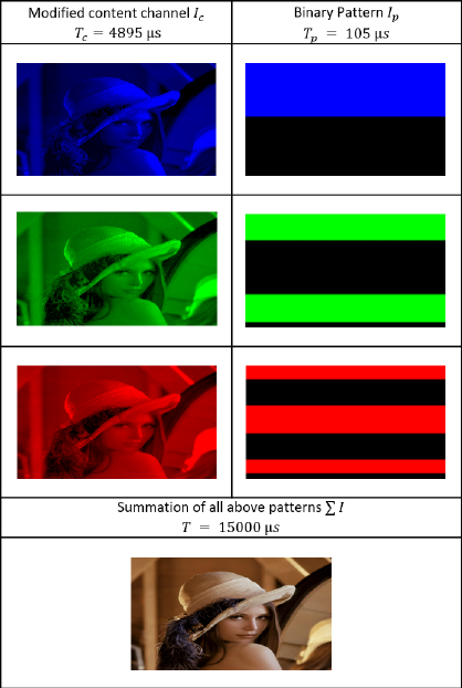
Figure 1: Illustration of the pattern embedding method.
The DMD used in this work is the Texas In-
struments DLP 6500 Lightcrafter engine (lig, 2016),
which projects colour by consecutive alternating of
coloured LED sources. As a result, patterns can
be embedded imperceptibly in each colour channel,
yielding 3 embedded patterns per frame. Exemplar
modified colour channels are displayed in Figure 1,
in which I represents an unmodified content channel
and T corresponds to a frame rate of 200 Hz.
The proposed method offers 2 major advantages
over previously presented imperceptible continuous
pattern embedding methods:
• It can operate at the maximum speed of the projec-
tor, unlike flicker fusion, which is limited to half
of the projector’s speed, and;
• It maintains the luminous power of the projected
image, unlike reverse-engineered dithering which
creates significant radiometric distortion,
4 STRUCTURED LIGHT
Structured light methods facilitate the establishment
of correspondences between camera and projector
pixels through spatial and/or temporal encoding of the
projected signal. While our work can be used with a
host of structured light encoding methods, we chose
grey code as effective for high-speed synchronized
capture. Grey code is a well-known method for tem-
poral encoding, using n patterns to yield 2
n
points of
correspondence in a single dimension. Finer and finer
patterns are projected and overlaid until each pixel
possesses a unique illumination sequence, known as a
codephrase. The locations of the transitions between
adjacent codephrases in each image plane are taken as
correspondences.
Temporally encoded structured light methods are
quite effective at extracting dense depth. However,
they have seen limited use in real time and dynamic
applications due to their requirement of a sequence
of images to produce a single depth image frame.
For grey code in particular, the accepted method
of categorizing each pixel in both the X and Y di-
rections at 1920×1080 resolution requires at least
ceil(log
2
(1920))+ceil(log
2
(1080)) = 22 patterns, as
well as an all-white and all-black frame for calibra-
tion.
Using the flicker fusion method at 60 Hz, this full
sequence of 24 patterns would be projected only 2.5
times per second. Reverse engineered dithering em-
bedding methods operating at 120 Hz would display
the sequence 5 times per second. Using the proposed
approach to embed patterns in each content frame
colour channel, this rate has been increased to 8.3 full
sequences per second. Our method further increases
the frame rate by using stereo rectification so that only
horizontal grey code patterns need be projected, effec-
tively halving the number of grey code patterns pro-
jected. The frame rate can be increased again by re-
ducing the number of patterns, at the expense of re-
ducing resolution along the X and Y axes.
5 STEREO RECTIFICATION
A rectifying transformation calculated during pre-
processing is used to reduce the correspondence prob-
lem to a 1D search across conjugate epipolar lines, as
illustrated in Figure 2. The red lines passing through
Figure 2 (b) and (d) represent epipolar lines, which in-
tersect the structured light stripes at the same horizon-
tal coordinate in both images; what changes is the ver-
tical point in the epipolar line on which the stripes fall.
The vertical correspondence can best be viewed at the
edge of the pattern, where the line passes through the
same smaller subset of stripes at the same points in
both images.
In this way rectification simplifies structured light
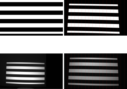
(a) Structured light pattern
as sent to projector
(b) and rectified
(c) the same pattern as re-
covered by the camera
(d) and rectified
Figure 2: Example of stereo rectification showing vertical
epipolar alignment.
encoding. Rather than encoding along both axes to
establish pixel disparity in the X and Y dimensions,
we need only encode along a single axis. Each code-
phrase will occur only once per image plane along
each epipolar line. Establishing correspondence is
thus reduced to a linear search.
Recification can align the epipolar lines in either
the X or Y dimension, meaning every real space point
will share the same X coordinate in both image planes
or the same Y coordinate. In this case, vertical rectifi-
cation resulting in the vertical alignment of the cam-
era and projector image planes is preferred over hor-
izontal. This orientation aligns the long edges of the
image plane (Figure 2) and creates a larger number of
shorter epipolar lines when compared with horizontal
rectification, as the system’s image width is greater
than its height. Horizontal rectification would resolve
to 1080 × 2
8
= 276k points for 8 patterns, while ver-
tical rectification would resolve to 1440 × 2
8
= 368k
points per depth image frame.
6 PATTERN SELECTION
With the correspondence problem reduced to a single
axis, what remains is to encode the points along each
axis uniquely so that linear disparity may be recov-
ered. Each epipolar line is 1080 pixels long in each
image plane. To fully characterize these lines would
require ceil(log
2
(1080)) = 11 patterns, as well as a
full black and full white frame for calibration of lu-
minous intensity levels.
To strike a balance between performance and res-
olution we chose to use 8 binary patterns, providing
2
8
= 256 points of depth along each epipolar line.
Also present is a single white frame for luminous in-
tensity calibration. A second (black) frame is nor-
mally used so that a midpoint between high and low
illumination levels can be used for thresholding. Its
omission renders the system more vulnerable to er-
ror from very high or very low reflectance surfaces as
well as ambient light. Our experiments have shown
this to be an acceptable trade-off in this system. Us-
ing 9 patterns yields an operating rate of 22.2 full se-
quences per second, as limited by the camera’s cap-
ture rate.
7 EXPERIMENTAL RESULTS
A set of experiments was executed to characterize the
bandwidth of the imperceptible range image extrac-
tion and the accuracy of the range data. The projec-
tor used was the Optecks RGB LightCrafter 6500 en-
gine, based on the Texas Instruments DLP 6500 mod-
ule (lig, 2016). This device bundles 3-channel LED
illumination with a high-performance DMD and op-
tics to create a powerful and flexible projection plat-
form at 1920x1080 resolution. Its most notable char-
acteristics are the ability to expose 8-bit patterns for
a minimum of 4046µs and binary patterns for 105 µs,
as well as a programmable hardware trigger.
Combined with this engine is a PointGrey Black-
fly S machine vision camera, capable of capturing at
over 200 Hz at full 1440x1080 resolution. The cam-
era is synchronized via the hardware trigger and is
capable of a 9 µs response time and a minimum 4 µs
exposure time. Processing is performed on an AMD
Ryzen 5 1600 MHz 6-core processor with 2 x 8Gb
2133 MHz RAM cards and a Samsung SM961 256
Gb solid-state drive. The hardware synchronized pro-
cam system is shown in Figure 3
7.1 Calibration
Two methods were used to calibrate the system. First,
Zhang’s well-known method (Zhang, 2000) was used
to perform intrinsic calibration on the camera to re-
move radial distortion. Next, procam stereo calibra-
tion as presented by Martynov et al. (Martynov et al.,
2011) was used to compute stereo rectification trans-
forms for both the projector and camera. These trans-
forms were equipped to handle relatively small intrin-
sic distortion so the intrinsics of the projector were
not addressed outside these transforms.
Stereo reprojection was used to determine calibra-
tion accuracy. This test began with drawing a line
visible in both image planes and then rectifying each
image. Assuming a perfect rectification transform,
both rectified views of the line would match exactly.
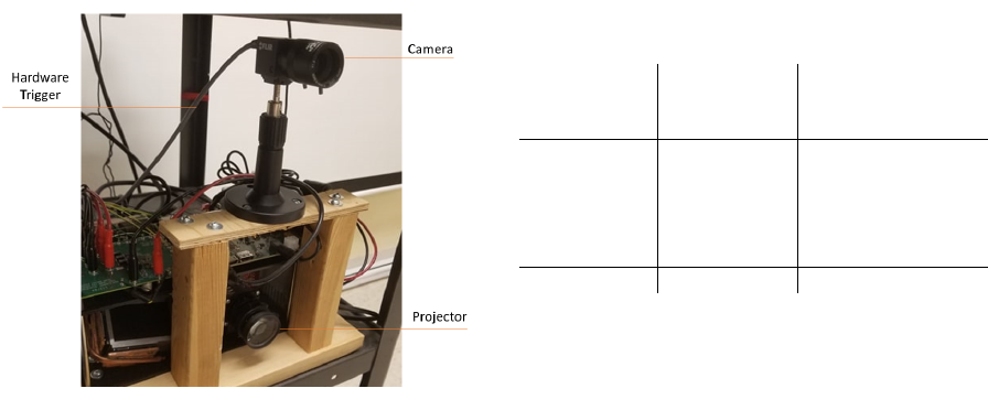
Figure 3: The hardware synchronized vertically co-axial
procam system employed in this work.
In reality, some pixel disparity occurs and can pro-
vide a measure of the accuracy of the computed trans-
forms. First, the OpenCV function used to compute
the stereo rectification transforms minimizes repro-
jection error as part of its functionality. It returns
the transform associated with the lowest reprojection
error, along with the error itself. To confirm the re-
sults given, a script was used to perform another re-
projection test with the computed calibration param-
eters (Bradski and Kaehler, 2008). The OpenCV test
yielded a pixel error ε = 1.16 pixels and the custom
test yielded ε =1.28 pixels.
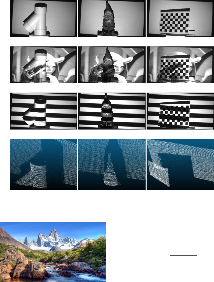
7.2 Range Image Formation
Figure 4 shows some examples of the method. Sev-
eral scenes are presented and then shown with 1 of
the 9 patterns overlayed and finally, the fully recon-
structed depth scene is shown as a point cloud.
The pipe represents a near-lambertian curved sur-
face and as expected, shows strong continuous depth
reconstruction. The gnome presents dense features
with varying colours and reflectivity, but the binary
nature of the patterns and high calibration accuracy
render these issues inconsequential and strong con-
tinuous depth is present. Finally, the chessboard
presents a highly reflective surface with stark colour
contrast – a challenging scenario for structured light
patterns. Again, accurate dense depth points were ex-
tracted.
7.3 Imperceptibility
To test the degree of imperceptibility of the method,
patterns were embedded in the image shown in Fig-
ure 5. This image was selected to demonstrate a vari-
Table 1: Mean and standard deviation of disparity points
across 5 projector-plane distances.
Plane
distance
(cm)
Mean error
(pixels)
Standard
deviation
(pixels)
100 2.65 2.69
125 2.70 3.32
150 3.07 3.85
175 2.39 3.73
200 2.51 3.00
Total 2.69 3.40
ety of different characteristics, including regions that
are bright and dark and smooth and sharp. There is
also a significant region that is dominated by blue,
so chosen to test if patterns could still be embedded
when some colour channels were barely present.
In empirical testing with over 10 subjects, the sys-
tem was demonstrated as imperceptible, with no arti-
facts or obvious disruptions to the image being visible
to any observer. In addition, the patterns embedded in
the red and green channels displayed no loss in quality
of recovery. This is due to the high level of contrast
in the acquired binary patterns, which renders them
quite resilient to dimming.
7.4 Plane Fitting
To assess the accuracy of the extracted disparity val-
ues, a series of 100 disparity images of a flat plane was
collected at 5 different projector-surface distances.
Each of these images was converted into 3D coordi-
nates and a plane fitting was performed. Then, the
ideal disparity corresponding to the fitted plane was
calculated at each image plane coordinate. This ideal
disparity was compared to the actual disparity mea-
sured at that point to determine the accuracy of the
system. Figure 6 shows the percentage of points that
lie within each integer error bound from 0-20 pixels
across all collected disparity images. The mean and
standard deviation of the pixel disparity error at each
tested distance is visible in Table 1.
To assess the repeatability of the system, a random
error test was performed. This test quantifies the stan-
dard deviation of each disparity measurement across
100 images of a static scene, as per Equation 8. Here,
N denotes the number of disparity measurements, d
i
represents the disparity value in image i and
¯
d denotes
the mean value computed over all disparity measure-
ments d
i
(ran, 2019).
When determining the variance at a pixel location
across a series of disparity frames, we must consider
that not all pixels will possess a disparity measure-
ment in each frame. We can thus define the pixel
confidence threshold as the percentage of disparity
(a) (b) (c)
(d) (e) (f)
(g) (h) (i)
(j) (k) (l)
Figure 4: Several objects presented under flat white illumination (a-c), illuminated by the projected content in which patterns
are embedded imperceptibly (d-f), illuminated by an exemplar binary pattern (g-i) and finally reconstructed as a cloud of
extracted depth points(j-l).
Figure 5: Image used for pattern embedding.
frames in which a pixel must be illuminated to accept
that pixel as valid across the series. Figure 7 shows
the relationship between the pixel confidence thresh-
old and the random error at all tested projector-plane
distances. It also displays the trade-off to a higher
pixel confidence threshold in the average number of
valid disparity points in each frame.
E
random
=
s
∑
N
i=1
(d
i
−
¯
d)
2
N
(8)
7.5 Operating Speed
The system’s operating speed is divided into 3 sec-
tions: pattern projection rate, camera capture rate, and
processing speed. The rates at which each section can
process all 9 patterns are shown in Table 3. As is ap-
parent, the projector and camera speeds are closely
aligned. The camera can return the complete set of 9
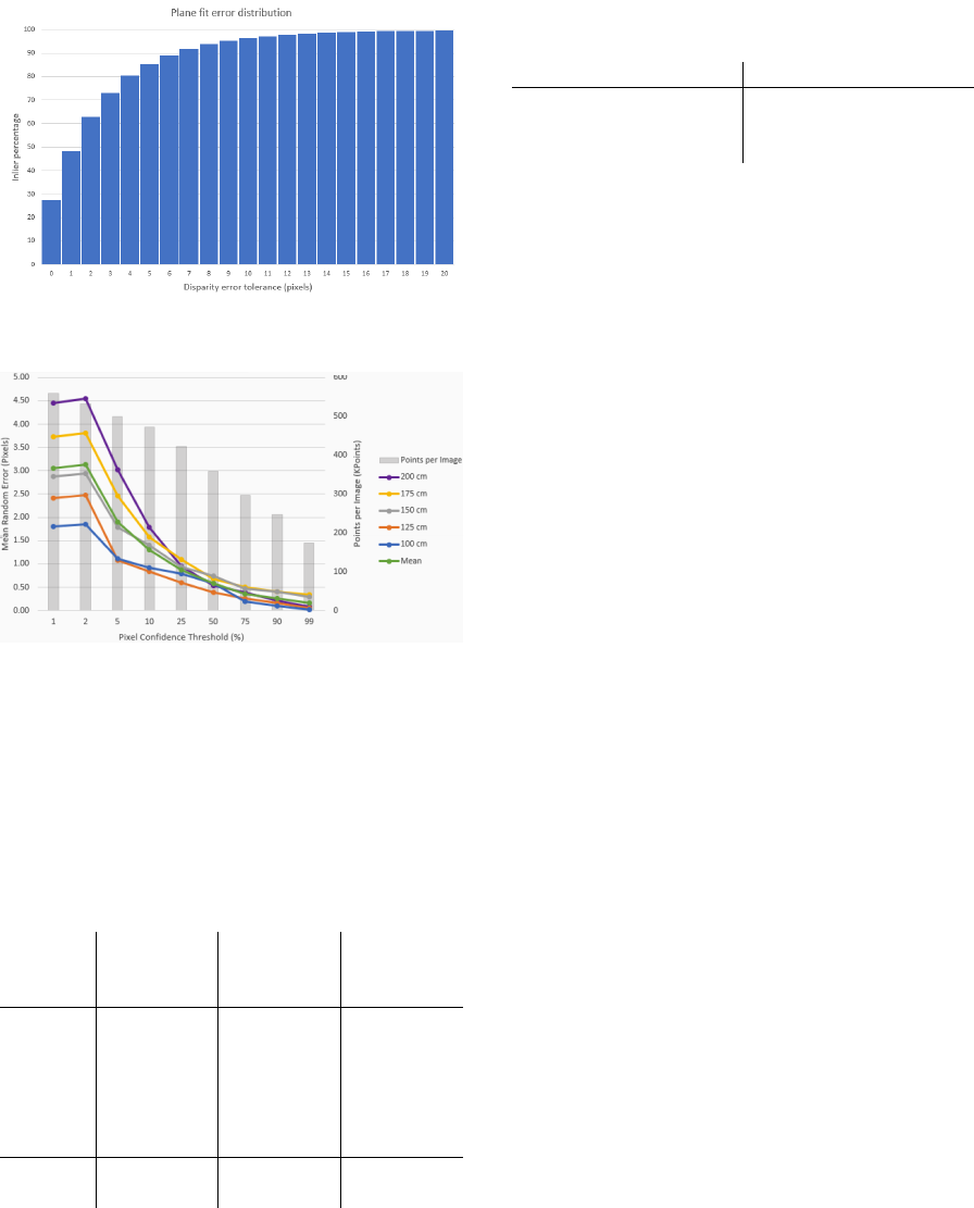
Figure 6: Percentage of inlier points as a function of dispar-
ity error tolerance for a fitted plane across 500 depth frames.
Figure 7: Effect of the pixel confidence threshold on the
random error and disparity points per frame.
patterns at 22.2 Hz, slightly slower than the 26.8 Hz
at which the projector can embed them imperceptibly.
Table 2 shows a comparison of the system’s cur-
rent performance in depth points per second as com-
pared with the Kinect V1 and V2 (Zhang, 2012) and
the Zivid One (Salmi et al., 2018).
Table 2: Points per second comparison.
Resolution
(points)
Rate of
operation
(Hz)
Points per
second
(Mpoints/S)
Kinect
V1
633x495 30 9.20
Kinect
V2
512x424 30 6.51
Zivid
One
1900x1200 13 29.9
Proposed
method
1400x256 22.2 7.96
8 CONCLUSION
This work presents a novel approach to temporally en-
coded structured light depth sensing suitable for real
Table 3: Current operating rates of the 3 main system com-
ponents.
System Component Operating Rate (Hz)
Camera 22.2
Projection 26.8
Processing 30.2
time applications, including those that benefit from
imperceptibility. The approach is particularly effec-
tive for dynamic projection mapping. The compa-
rable systems in Table 2 have been implemented in
FPGA and/or VLSI, rather than a CPU as with the
proposed approach, and so they have been optimized
for time performance. This implies the potential for
the proposed method to further and significantly ex-
ceed the current bandwidth while maintaining imper-
ceptibility. Any upgrades to processing speed would
be predicated on concurrent upgrades to the operat-
ing rate of the projector and camera, either through
hardware upgrades or algorithmic changes.
Quantitative analysis of imperceptibility in this
work was impeded in this case by the Lightcrafter
engine’s inability to dynamically modify content. In
the future, the system will be fitted with the ability
to dynamically modify projected content, and a thor-
ough study will be set up to quantitatively assess the
imperceptibility of the embedding method. This will
consist of alternating frames or sections of video with
and without embedded patterns and recording differ-
ences noted by observers. These tests will provide a
more complete picture of the method’s impact on the
fidelity of projection.
ACKNOWLEDGEMENTS
The authors would like to acknowledge Epson
Canada, the Natural Sciences and Engineering Re-
search Council of Canada, and the Ontario Centres
of Excellence, for their support of this work.
REFERENCES
(2016). Lightcrafter 6500 Evaluation Module. Texas In-
struments.
(2019). Azure kinect dk depth camera.
https://docs.microsoft.com/bs-latn-ba/azure/Kinect-
dk/depth-camera. Accessed: 2019-06-29.
Bandyopadhyay, D., Raskar, R., and Fuchs, H. (2001). Dy-
namic shader lamps: Painting on movable objects. In
Proceedings IEEE and ACM International Symposium
on Augmented Reality, pages 207–216. IEEE.
Bermano, A. H., Billeter, M., Iwai, D., and Grundh
¨
ofer, A.
(2017). Makeup lamps: Live augmentation of human
faces via projection. In Computer Graphics Forum,
volume 36, pages 311–323. Wiley Online Library.
Bradski, G. and Kaehler, A. (2008). Learning OpenCV:
Computer vision with the OpenCV library. ” O’Reilly
Media, Inc.”.
Cotting, D., Naef, M., Gross, M., and Fuchs, H. (2004).
Embedding imperceptible patterns into projected im-
ages for simultaneous acquisition and display. In Pro-
ceedings of the 3rd IEEE/ACM International Sympo-
sium on Mixed and Augmented Reality, pages 100–
109. IEEE Computer Society.
Dai, J. and Chung, R. (2011). Head pose estimation by im-
perceptible structured light sensing. In 2011 IEEE In-
ternational Conference on Robotics and Automation,
pages 1646–1651. IEEE.
Dai, J. and Chung, R. (2012). Making any planar surface
into a touch-sensitive display by a mere projector and
camera. In 2012 IEEE Computer Society Conference
on Computer Vision and Pattern Recognition Work-
shops, pages 35–42. IEEE.
Factura, B., LaPerche, L., Reyneri, P., Jones, B., and
Karsch, K. (2018). Lightform: procedural effects for
projected ar. In ACM SIGGRAPH 2018 Studio, page 6.
ACM.
Grundh
¨
ofer, A., Seeger, M., Hantsch, F., and Bimber, O.
(2007). Dynamic adaptation of projected impercepti-
ble codes. In Proceedings of the 2007 6th IEEE and
ACM International Symposium on Mixed and Aug-
mented Reality, pages 1–10. IEEE Computer Society.
Kagami, S. and Hashimoto, K. (2015). Sticky projection
mapping: 450-fps tracking projection onto a moving
planar surface. In SIGGRAPH Asia 2015 Emerging
Technologies, page 23. ACM.
Kuroki, Y., Nishi, T., Kobayashi, S., Oyaizu, H., and
Yoshimura, S. (2007). A psychophysical study of
improvements in motion-image quality by using high
frame rates. Journal of the Society for Information
Display, 15(1):61–68.
Lee, J. C., Hudson, S. E., and Tse, E. (2008). Foldable in-
teractive displays. In Proceedings of the 21st annual
ACM symposium on User interface software and tech-
nology, pages 287–290. ACM.
Lohry, W. and Zhang, S. (2014). High-speed absolute
three-dimensional shape measurement using three bi-
nary dithered patterns. Optics express, 22(22):26752–
26762.
Martynov, I., Kamarainen, J.-K., and Lensu, L. (2011). Pro-
jector calibration by “inverse camera calibration”. In
Scandinavian Conference on Image Analysis, pages
536–544. Springer.
McDowall, I. and Bolas, M. (2005). Fast light for display,
sensing and control applications. In Proc. of IEEE
VR 2005 Workshop on Emerging Display Technolo-
gies (EDT), pages 35–36.
Narasimhan, S. G., Koppal, S. J., and Yamazaki, S. (2008).
Temporal dithering of illumination for fast active vi-
sion. In European Conference on Computer Vision,
pages 830–844. Springer.
Narita, G., Watanabe, Y., and Ishikawa, M. (2015). Dy-
namic projection mapping onto a deformable object
with occlusion based on high-speed tracking of dot
marker array. In Proceedings of the 21st ACM Sym-
posium on Virtual Reality Software and Technology,
pages 149–152. ACM.
Panasonic (2017). Real time tracking & projection map-
ping.
Park, H., Lee, M.-H., Seo, B.-K., Jin, Y., and Park, J.-I.
(2007). Content adaptive embedding of complemen-
tary patterns for nonintrusive direct-projected aug-
mented reality. In International Conference on Virtual
Reality, pages 132–141. Springer.
Raskar, R., Welch, G., Cutts, M., Lake, A., Stesin, L., and
Fuchs, H. (1998). The office of the future: A uni-
fied approach to image-based modeling and spatially
immersive displays. In Proceedings of the 25th an-
nual conference on Computer graphics and interac-
tive techniques, pages 179–188. ACM.
Raskar, R., Welch, G., Low, K.-L., and Bandyopadhyay, D.
(2001). Shader lamps: Animating real objects with
image-based illumination. In Rendering Techniques
2001, pages 89–102. Springer.
Resch, C., Keitler, P., and Klinker, G. (2015). Sticky
projections-a model-based approach to interactive
shader lamps tracking. IEEE transactions on visual-
ization and computer graphics, 22(3):1291–1301.
Salmi, T., Ahola, J. M., Heikkil
¨
a, T., Kilpel
¨
ainen, P., and
Malm, T. (2018). Human-robot collaboration and
sensor-based robots in industrial applications and con-
struction. In Robotic Building, pages 25–52. Springer.
Silapasuphakornwong, P., Unno, H., and Uehira, K. (2015).
Information embedding in real object images using
temporally brightness-modulated light. In Applica-
tions of Digital Image Processing XXXVIII, volume
9599, page 95992W. International Society for Optics
and Photonics.
Zhang, Z. (2000). A flexible new technique for camera cal-
ibration. IEEE Transactions on pattern analysis and
machine intelligence, 22.
Zhang, Z. (2012). Microsoft kinect sensor and its effect.
IEEE MultiMedia, 19(2):4–10.
