
Development of Bioinspired Exosuit Actuated with Hydro Muscles
and Novel Compact Robotic Flow Control Valve
Julia D’Agostino
1,2,3,
*
, Ellen Clarrissimeaux
2,3,*
, Shannon Moffat
1,2
, Juan D. Florez-Castillo
1,2
,
Felix Sanchez
1,2
, Matthew Bowers
1,2
and Marko Popovic
1,2,4,5
1
Robotics Engineering Program, WPI, 100 Institute Road, Worcester, Massachusetts, U.S.A.
2
Popovic Labs, WPI, 100 Institute Road, Worcester, Massachusetts, U.S.A.
3
Mechanical Engineering Department, WPI, 100 Institute Road, Worcester, Massachusetts, U.S.A.
4
Physics Department, WPI, 100 Institute Road, Worcester, Massachusetts, U.S.A.
5
Biomedical Engineering Department, WPI, 100 Institute Road, Worcester, Massachusetts, U.S.A.
Keywords: Exosuit, Wearable Robotics, Valve, Hydro Muscle, Fluid Actuator.
Abstract: The biologically inspired, wearable, exo-muscular suit has been proposed as a cost-effective, fluidly actuated
device for lower-limb physical therapy as well as for assistance with activities of daily living. The exosuit,
actuated with 12 biomimetic Hydro Muscles independently controlled with 12 5-way inexpensive, off-the-
shelf, on-off solenoid valves, has been designed, manufactured, and tested on a lightweight, biomimetic
human skeletal model. The results from testing suggested a necessity for more advanced fluid flow
management support system in the form of affordable, lightweight, and compact valves suitable for robotics
applications. To meet these metrics and fulfil the requirements of the exosuits fluid flow management system
the Compact Robotic Flow Control Valve was designed, manufactured, and tested. The CRFC Valve is lighter,
more compact, more controllable, and less expensive than any other similar valve currently on the market.
1 INTRODUCTION
Because form and function are naturally intertwined,
biologically inspired robots following the structure of
the human
body
are an attractive direction for the
advancement of a variety of biomedical applications.
Such applications include prosthetic limbs, braces,
exoskeletons, and exo-muscular suits that can be used
for physical therapy, activities of daily living (ADL),
and tasks requiring augmentation of common able-
bodied physical capabilities (Popovic, 2013; Popovic
2019).
There are a number of biologically inspired
muscles and corresponding systems (Popovic 2019).
Series Elastic Actuators (Pratt and Williamson,
1995), i.e. position controlled actuators in series with
elastic elements have been used in systems (Herr et
al, 2012; Blaya and H. Herr, 2014) with conventional
linear actuators as well as in the context of cable
driven systems (Kesner et al, 2011; Hunt et al, 2012;
Galiana et al, 2012; Mao and Agrawal, 2012; Asbeck
et al, 2013; Asbeck et al, 2014; Saint-Elme et al,
*
These authors contributed equally to this work.
2017). Similarly, soft and compliant fluid actuated
muscles have been actuating devices (Ueda et al,
2010; Park et al, 2014; Kurumaya et al, 2016)
utilizing McKibben Muscles and devices (McCarthy
et al, 2014; Sridar et al, 2016; Bowers et al, 2017)
employing Hydro Muscles (Sridar et al, 2016;
McCarthy et al, 2014).
McKibben muscles are currently the most popular
fluidly actuated soft artificial muscles (Popovic,
2019). Unfortunately, McKibben muscles are not
very efficient and cannot support a biologically
realistic muscle strain (Popovic, 2019; Sridar et al,
2016; Bowers et al, 2017). The Hydro Muscle,
utilized here, has excellent strain and energy
efficiency properties (Miriyev et al 2017) and can
closely mimic biological muscle dynamics (Popovic,
2019).
Many robotics researchers in academic settings
avoid hydraulically and pneumatically operated
systems in particular due to leaks, need for custom
parts, and complexities associated with a fluid
circulation system in which the entire system may be
40
D’Agostino, J., Clarrissimeaux, E., Moffat, S., Florez-Castillo, J., Sanchez, F., Bowers, M. and Popovic, M.
Development of Bioinspired Exosuit Actuated with Hydro Muscles and Novel Compact Robotic Flow Control Valve.
DOI: 10.5220/0008948600400049
In Proceedings of the 13th International Joint Conference on Biomedical Engineering Systems and Technologies (BIOSTEC 2020) - Volume 1: BIODEVICES, pages 40-49
ISBN: 978-989-758-398-8; ISSN: 2184-4305
Copyright
c
2022 by SCITEPRESS – Science and Technology Publications, Lda. All rights reserved
affected by local changes or disturbances. However,
fluid operated systems provide many advantages,
especially for wearable robotics where size and mass
matter significantly. Instead of having one strong and
heavy dedicated electric motor per actuated degree of
freedom, here only one strong and heavy electric
motor (e.g. pump) is needed for all actuated degrees
of freedom.
However, valves are necessary to operate
pneumatic and hydraulic systems. Valves that are cost
effective, lightweight, compact, can be electronically
controlled, and support a reasonable range of
pressures appropriate for wearable robotics
applications are not widely available on the market.
The Compact Robotic Flow Control (CRFC) Valve,
addressed here, was created to resolve these market
shortcomings, and to work in conjunction with the
Hydro Muscle system. When integrated, Hydro
Muscles and the CRFC Valve have the potential for
implementation in a rehabilitation robot system or a
wearable assistive exosuit that is lightweight, low-
cost, and has capabilities for fine control and
customization.
Presented here first is an overview of the design
and testing of an exosuit utilizing Hydro Muscles
(Curran et al, 2018; Moffat 2019) followed by an
explanation for the need for an advanced novel flow
control valve in Section 2. The details of the CRFC
Valve design, testing, and discussion are addressed in
Section 3.
2 EXOSUIT
The biologically inspired, wearable, exo-muscular
suit has been proposed as a cost-effective, fluidly
actuated device for lower-limb physical therapy as
well as for assistance with activities of daily living.
2.1 Exosuit: Modelling and Mechanics
The exosuit was modelled based on a lower limb
skeletal structure by 3B Scientific (Functional
Physiological Skeleton Model) with bungee cord
ligaments that allowed for lifelike degrees of
freedom.
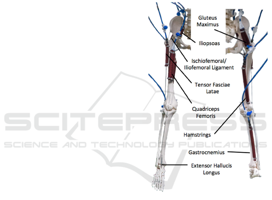
The exo-muscular suit was modelled with 6
custom-made Hydro Muscles per each leg. This
retained anatomical integrity addressed the most
active biological muscles during regular gait cycle:
iliopsoas, tensor fasciae latae, quadriceps femoris,
gluteus maximus, hamstrings (biceps femoris and
semitendinosus), and gastrocnemius. Additional
passive spring structures were used to model the
extensor hallucis longus muscle (providing ankle
dorsiflexion), as well as the iliofemoral and
ischiofemoral ligaments.
The Hydro Muscles were placed in series with
tendons made out of Spiderwire (Spiderwire Stealth),
a thick fishing line. The series is attached to eye hooks
with threaded inserts placed at the approximated
anatomical muscle origin and insertion locations
(Hoy et al, 1990) (Fig. 1 and 2).
Figure 1: Exosuit muscle model.
Each Hydro Muscle length was uniquely
determined for the cross sectional profile of the
muscle. First, the maximal change in length of each
Hydro Muscle was obtained (assuming an always
slightly tensed inelastic tendon) based on average
biological joint angle trajectories of 15 healthy
individuals walking at a self-selected speed (Lewis
and Sahrmann, 2015). Then, by relating pressure to
Hydro Muscle length while assuming maximal
pressure of 0.69 MPa (100 psi) the unpressurized,
fully contracted Hydro Muscle length was
determined.
All 6 Hydro Muscles were composed of surgical
latex tubing and polyester Uber Hose (Uberhose153)
Development of Bioinspired Exosuit Actuated with Hydro Muscles and Novel Compact Robotic Flow Control Valve
41
sheathing. The tubing dimensions were 12.7 mm (1/2
in) outer diameter and 6.35 mm (1/4 in) inner
diameter. The Hydro Muscle forces were adjusted
using manual flow control valves (Elbow Pneumatic
Flow Control Valve). The valve orifice was fine-
tuned to provide for the most optimal force output of
each muscle. After initial mechanical testing, the
models gluteus maximus and quadriceps femoris
were doubled up to provide more force, i.e. each of
these two model muscles was added with an extra
Hydro Muscle connected to the same valve as the
original Hydro Muscle.
In the earlier stages of Hydro Muscle
development, an electronically controlled, a 5-way
on-off solenoid, pilot operated valve (Pneumatic
Electric Solenoid Valve) was used in series with a
manual flow control valve (Elbow Pneumatic Flow
Control Valve) to direct air flow in and out of the
Hydro Muscle. The gait was controlled through a
state machine, in which each of the six major phases
of the gait cycle was defined as a state to set each
solenoid valve to high or low, to indicate that the
corresponding muscle should be elongated or
contracted, respectively (Table 1). The six phases for
state control were obtained from eight standard
biomechanics gait phases (Fig. 3) by grouping
Loading Response, Mid Stance and Terminal Stance
into a single phase. The state transitions were deduced
by feedback supplied by Inertial Measurement Units
(IMUs), (SparkFun).
The skeletal lumbar vertebra was connected via a
light, elastic spring to a stand made from 80/20 T-
slotted aluminum framing. A platform on the top of
that stand held all of the pneumatic valves and the
microcontroller (Arduino MEGA 2560). The Hydro
Muscles pneumatic umbilical system consisted of
6.35 mm (1/4 in) in diameter tubing with push
connects. The pressurized air was supplied from a
compressed air tank operating at 0.69 MPa (100 psi).
Finally, a 500W powered variable speed treadmill
(Exacme 6400-0108BK Treadmill) was placed
beneath.
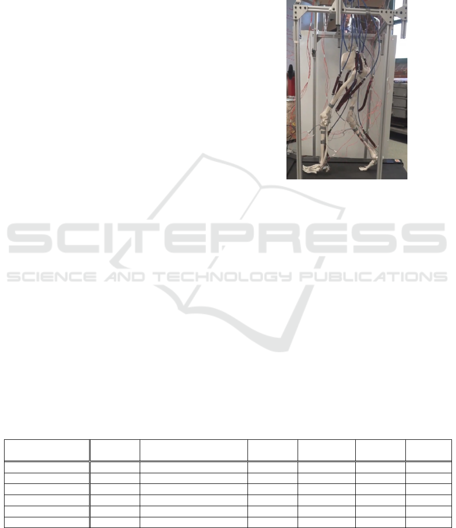
2.2 Exosuit: Experiment
A biomimetic skeletal structure, driven by the
exosuit, walked on a treadmill with the belt moving at
a constant pace of 0.28 m/s (Fig. 2). Movements were
recorded with IMU sensors and a high-speed camera.
Figure 2: Biomimetic skeletal structure driven by the
exosuit walking on a treadmill.
2.3 Exosuit: Results
The skeletal postures are compared (Streifeneder.
Ortho lab) to biological postures (Fig. 3). The joint
angle trajectories vs. percentage gait cycle are
contrasted with biological gait data for normal (Lewis
and Sahrmann, 2015), forward leaning (Lewis and
Sahrmann, 2015), and toe (Olensek and Matjacic,
2012) walking (Fig. 4).
The stride length was 0.78 m on average. The
biomimetic skeletal structure driven by the exosuit
was able to stand upright on its own and the light
tethering forces during the gait cycle were estimated
to
be less than 20% of the skeletal weight
(approximately 3.3 kg) based on inverted pendulum
Table 1: Muscles’ States.
Muscles’ States Heel Strike Stance Loading-Terminal Heel-Off Pre-Swing Mid-Swing
Terminal
Swing
Iliopsoas Expanded Expanded Expanded Contracted Contracted Contracted
Tensor Fasciae Latae Contracted Expanded Expanded Expanded Contracted Contracted
Quadriceps Femoris Contracted Contracted Expanded Expanded Expanded Contracted
Gluteus Maximus Expanded Contracted Contracted Contracted Expanded Expanded
Hamstrings Expanded Expanded Expanded Contracted Contracted Expanded
Gastrocnemius Expanded Expanded Contracted Contracted Contracted Expanded
BIODEVICES 2020 - 13th International Conference on Biomedical Electronics and Devices
42
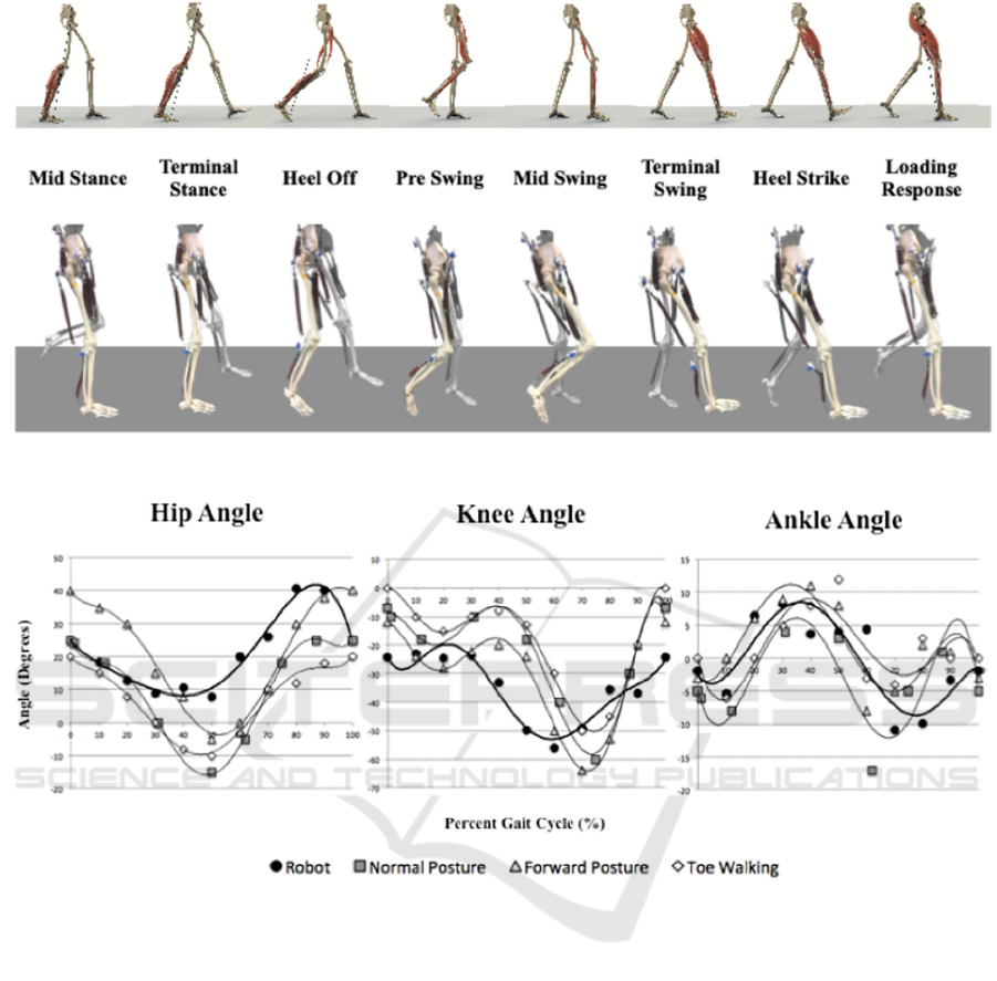
Figure 3: The eight gait phases: numerical simulation (top) and actual physical model in motion (bottom).
Figure 4: Joint angle trajectories for exosuit (Robot) and biological (Normal Posture, Forward Posture, Toe Walking) gait.
dynamics and estimated Center of Pressure and
Center of Mass locations.
2.4 Exosuit: Discussion
The lightly tethered biomimetic skeletal structure
driven by the exosuit was able to execute multiple
steps at a slow, steady pace and emulate close to
human-like walking trajectories.
The gait somewhat resembles a toe walking, upper
body forward leaning posture gait, similar to a
downhill walking gait. This was primarily due to lack
of active dorsiflexion and mechanical deficiency of
the skeletal model; that is the inability of the knee to
fully extend, resulting in a more bent hip in order to
provide enough foot clearance. Also, motion was not
as smooth due to the on-off, digital nature of solenoid
valves.
This preliminary system was clearly not designed to
carry the entire weight of the pneumatic system (e.g.
heavy air compressor), however, this should not
concern Lokomat-like applications. The Lokomat is a
robotic gait training system that helps people who
have suffered from various neurological or physical
conditions to regain the ability to walk. In comparison
to conventional Lokomat, which can resolve joint
level body movements, the proposed Hydro Muscle
actuated exosuit can even resolve the individual
muscle level actuation. Due to cost effectiveness, the
proposed Hydro Muscle actuated exosuit could
possibly be available for inexpensive, at-home use.
However, for more mobile wearable assistive
devices, weight, size, and controllability of the fluid
Development of Bioinspired Exosuit Actuated with Hydro Muscles and Novel Compact Robotic Flow Control Valve
43
circulation system must be improved. Hence a closed
(likely incompressible) fluid circulation system with
lightweight, small, and cost-effective flow control
valves is needed for an affordable, finely controlled
system. The next section proposes the use of the
Compact Robotic Flow Control (CRFC) Valve to
meet these expectations.
3 CRFC VALVE
The Compact Robotic Flow Control (CRFC) Valve
was designed, manufactured, and tested to fulfill the
requirements of the exosuit’s fluid flow management
system.
3.1 CRFC Valve: Methods
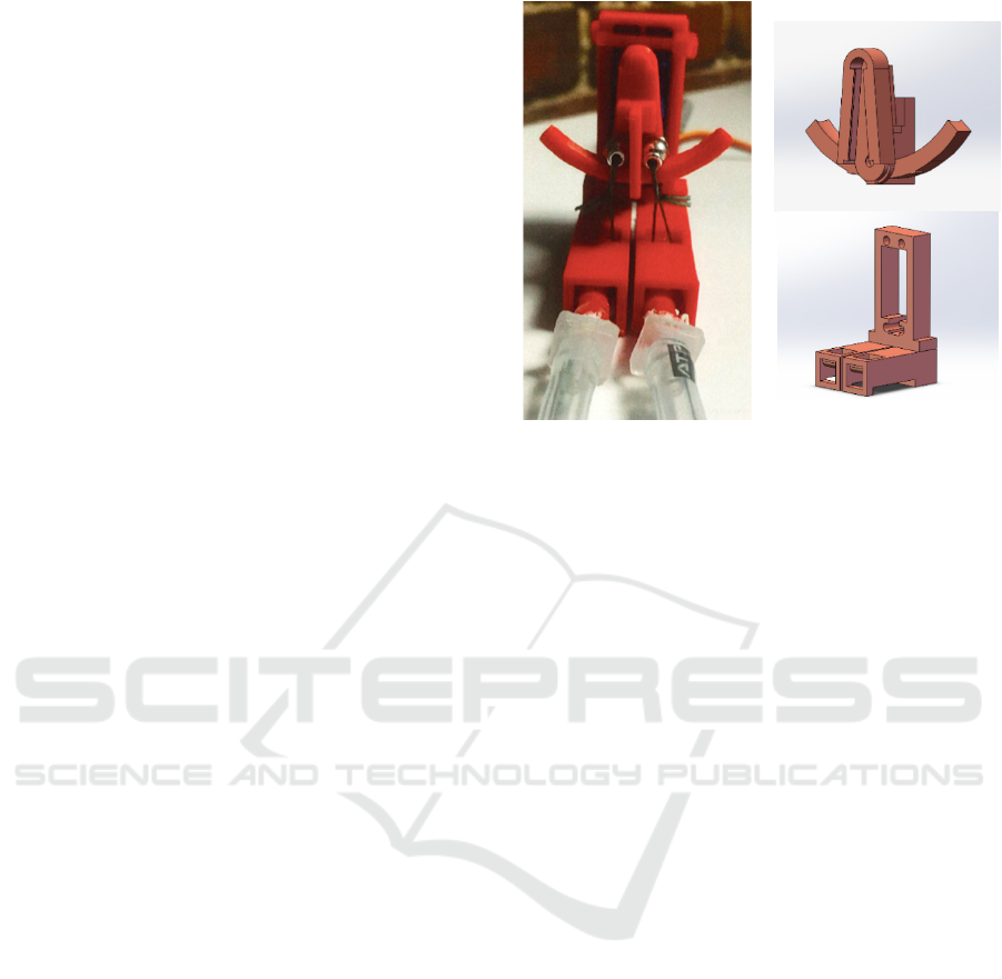
The patent pending CRFC Valve is a simply operated
flow control mechanism, with the ability to
manipulate liquid and gas. It uses a servo motor
attached to a choking mechanism that controls an
entry and exit port for fluids (Fig. 5). The CRFC
Valve consists of a servo motor, a 3D printed servo
horn CAM mount, 3D printed casing, two tubes
incased in fabric, and two CAM-follower beads
which are connected to strings that choke off the
tubing (Figure 5 and 6).
The valve is controlled by a 0.215 Nm, 0.08
sec/60 degree @6V, ~$10 USD priced servo motor
(MG90D High Torque Metal Gear), which allows the
CRFC Valve to quickly and robustly handle over 0.69
MPa (100 PSI) of pressure. This valve replaces and
improves upon the overall performance of the
previously used valve unit addressed in Section II.
Current construction of the CRFC Valve consists
of a 3D printed motor and tube casing, and a curved
element. The curved element is used similarly to a
cam mechanism, with two spherical cam followers
(beads), the servo motor, and two tubes serving as the
flow channels, which allow for bi-directional fluid
flow (Fig. 6). Of the two tubes, at least one or both
are closed at any given point in time. One tube serves
as a fluid input for an attached system, and the other
tube is the release tube.
For one-directional flow operations, only one of
these tubes would be necessary to serve as an inlet
and outlet. On the anterior side of the valve, the two
tubes merge with a Y connector to attach to the
desired device. On the posterior side of the valve, the
tubes are separate, allowing one to be connected to a
pressurizing device, while the other releases the fluid
when the tube is opened. This is the operational
configuration of a three-way valve used to conduct
Figure 5: CRFC Valve: physical model (left) and CAD of
motor casing (bottom right) and attachment (top right).
flow and control tests; however, this valve is capable
of a few other operational configurations due to its
mechanical layout as a two-position, parallel, two-
way valve (i.e. constrained 4-way valve).
Operation of the valve involves actuating the
servo motor to tilt the curved element, on which the
beads roll along a smooth track (to minimize friction),
so that a finely controlled choking or opening of the
flow channels is achieved. String looped around each
tube is attached to each corresponding bead, which
allows the flow to be controlled by the angle of the
servo motor. The string pulls the tubing upwards
against the proximal portion of the casing, which is
curved to provide a more gradual decline in the
choking angle while preventing fluid flow.
The current design incorporates 5mm wide, 1mm
thick surgical tubing encased in kite fabric, which
prevents ballooning and the possible bursting of the
tube, as well as adding additional protection against
friction from the string.
In the resting state, the servo is at a neutral,
symmetrical position, with Tube A and Tube B both
closed, as depicted in State 2 (Fig. 6, top). This
prevents flow to pass through either tube, as they are
both constricted in this state. Rotating the servo
counterclockwise will cause the string to loosen,
allowing Tube A to open, while Tube B will remain
constricted, and thus will remain closed (State 1).
This will allow flow only through Tube A in this state.
Rotating the servo clockwise will cause Tube B to
open, but Tube A will remain closed (State 3). This
will allow flow only through Tube B in this state. The
range of operational servo angles change the size of
BIODEVICES 2020 - 13th International Conference on Biomedical Electronics and Devices
44
the tube inlet/outlet, thus introducing intermittent,
analog stages of operation and flow.
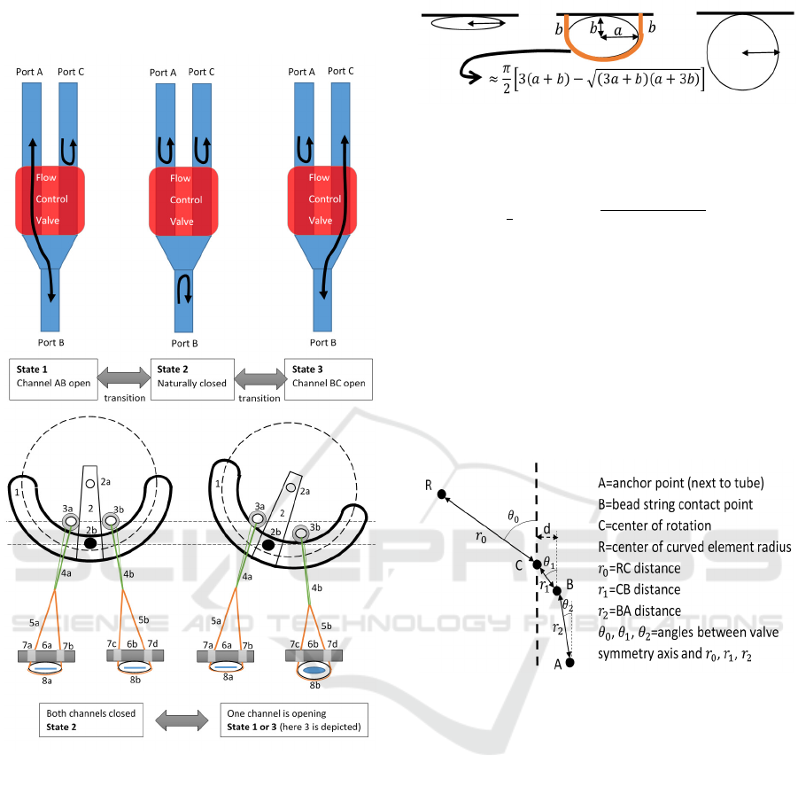
Figure 6: CRFC Valve: three states of the 3-port valve (top)
and principle of operation, front view (bottom). Curved
element (1, 2), CAM beads (3), Connecting strings (4, 5),
Casing base with holes (6, 7), Tubes (8).
3.1.1 Optimized Geometric Model
The valve model is dependent on the necessary
movement of the string to allow a tube to fully open,
the strain on the string on a side that is already closed,
and the desired dead-band angle for valve operation.
As shown, (Fig. 6 bottom), the curved element
rotation causes one bead to roll away from the valve’s
symmetry axis, thus reducing the distance between
the bead and the string’s anchor position above the
tube, and allowing the tube to open.
Figure 7: Tube choking - simplified elliptical model.
The total change in length needed for the tube to fully
open is obtained from the elliptical model (Fig. 7) as:
∆ 2
3
3
3
(1)
The general valve geometric model (Fig. 8) for the
initial resting state (with the servo at a neutral, zero-
degree angle) can be used to relate string slackening,
for the tube that is opening, and string strain, for the
tube that is closed, to the servo angle for a set of
specified valve parameters. This general
configuration includes two separate, symmetric,
curvature radii (of which only one R is shown in (Fig.
8)), and a dead band angle, which prevents the bead
from rolling until points R, B, and A are collinear.
Figure 8: The general valve geometric model.
The model’s parameters were optimized such that:
(1) the valve volume is minimized and scaled to the
appropriate operation conditions. (2) The slackening
for the fully open condition is attained within a
rotation range. (3) The amount of strain on the closed
side is minimized. (4) The dead band is sufficient to
account for servo positioning errors, to prevent
undesirable flow, while not being so large as to
substantially affect simple control. (5) The servo
motor can have sufficient torque as to easily close the
tube for the desired operational pressure.
The optimized geometric configuration has
coinciding R’s (Fig. 8) positioned on the valve
symmetry axis, i.e.
0
, AB axis (
) parallel to
the symmetry axis with
135
,
0
. The
values for
,
,
are dependent on the dimension of
the tube, overall valve, and moment that servo motor
can produce. As this model can be scaled, the
optimization procedure can be easily reproduced with
Development of Bioinspired Exosuit Actuated with Hydro Muscles and Novel Compact Robotic Flow Control Valve
45
different tube diameters, fluid pressures, and desired
valve dimensions for given servo.
The current CRFC valve has a curvature radius of
20 mm and a total operational angle span of 42
degrees that can be used to finely control flow. Its
dimensions are 6 5 2, though it only
occupies 2/3 of that volume due to its L-like shape,
and it has a total mass of only 28 grams. This
compares favorably to the 12 10 2 ,
276 gram, on-off flow control modules addressed in
Section II.
3.2 CRFC Valve: Experiments
1) Response Time: To test system response time, end-
stops were placed at the CRFC Valve’s maximal
operational angle and neutral position. Contact with
these end-stops triggered or stopped an internal timer
for the channel open and channel close movement at
100 psi of fluid pressure. Ten tests were recorded for
both air and water.
2) Flow Rate: The flow rate across a range of servo
angles was determined by taking the steady state flow
rate readings at 6 degree increments from 0 (fully
closed) to 42 degrees (fully open). The test setup for
air consisted of a compressed air reservoir connected
to a valve inlet and a digital anemometer at the outlet.
Similarly, the test setup for water consisted of a 12V
diaphragm pump connected to a valve inlet and a
digital paddle-wheel flow meter at the outlet.
3) Hydro Muscle speed: To address the servo angle in
relation to the Hydro Muscle elongation speed, the
rate of elongation was collected with the curved valve
attachment being rotated at various degrees and
timing the full elongation of a 10.4cm Hydro in
contracted state.
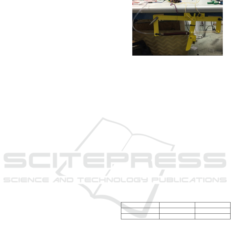
4) Controllability: The controllability of the CRFC
Valve using both air and water were evaluated with
the test setup seen in Figure 9.
A simple rigid element (‘leg’) was attached with a pin
joint to a fixed base, and actuated by a Hydro
Muscle. A desired ‘leg’ angular trajectory was
specified in the form of absolute value of the sine
function over period of 2 seconds. A simple
proportional, dead-band adjusted controller was
developed for control of the servo motor. The ‘leg’
angular displacement values were provided by a
potentiometer. The same test was performed with 5-
way pneumatic solenoid valve, which utilized a
custom, pseudo-analog, PWM loop with a cycle time
of 5 ms and a tuned P-controller.
For the air test, an air compressor maintained a
constant pressure of 0.69 MPa (100 psi), and the
exhaust was vented into the ambient space. For the
Figure 9: Test setup for controllability of CRFC Valve with
3D printed rigid element.
the water test, a 12V pump with an accumulator
maintained steady fluid pressure in closed loop
hydraulic system.
3.3 CRFC Valve: Results
1) Response Time: The average CRFC Valve
response times for both air and water at 0.69 MPa
(100 PSI) are shown in Table 2. According to
information obtained directly from the manufacturer,
the specified solenoid valve has a response time
between 1 and 2 seconds to fully transition between
closed and open states.
2) Flow Rate: The flow rate vs servo angle (Fig. 10).
3) Hydro Muscle Speed: The result of test relating
servo angle to the Hydro Muscle elongation speed
exhibits
-value of 0.967 (Fig. 11).
4) Controllability: The results of the controllability
experiments (Fig. 12).
Table 2: CRFC Valve response time for full state transition.
Response Open to Closed Closed to Open
Water 75 ms 70 ms
Air 70 ms 65 ms
BIODEVICES 2020 - 13th International Conference on Biomedical Electronics and Devices
46
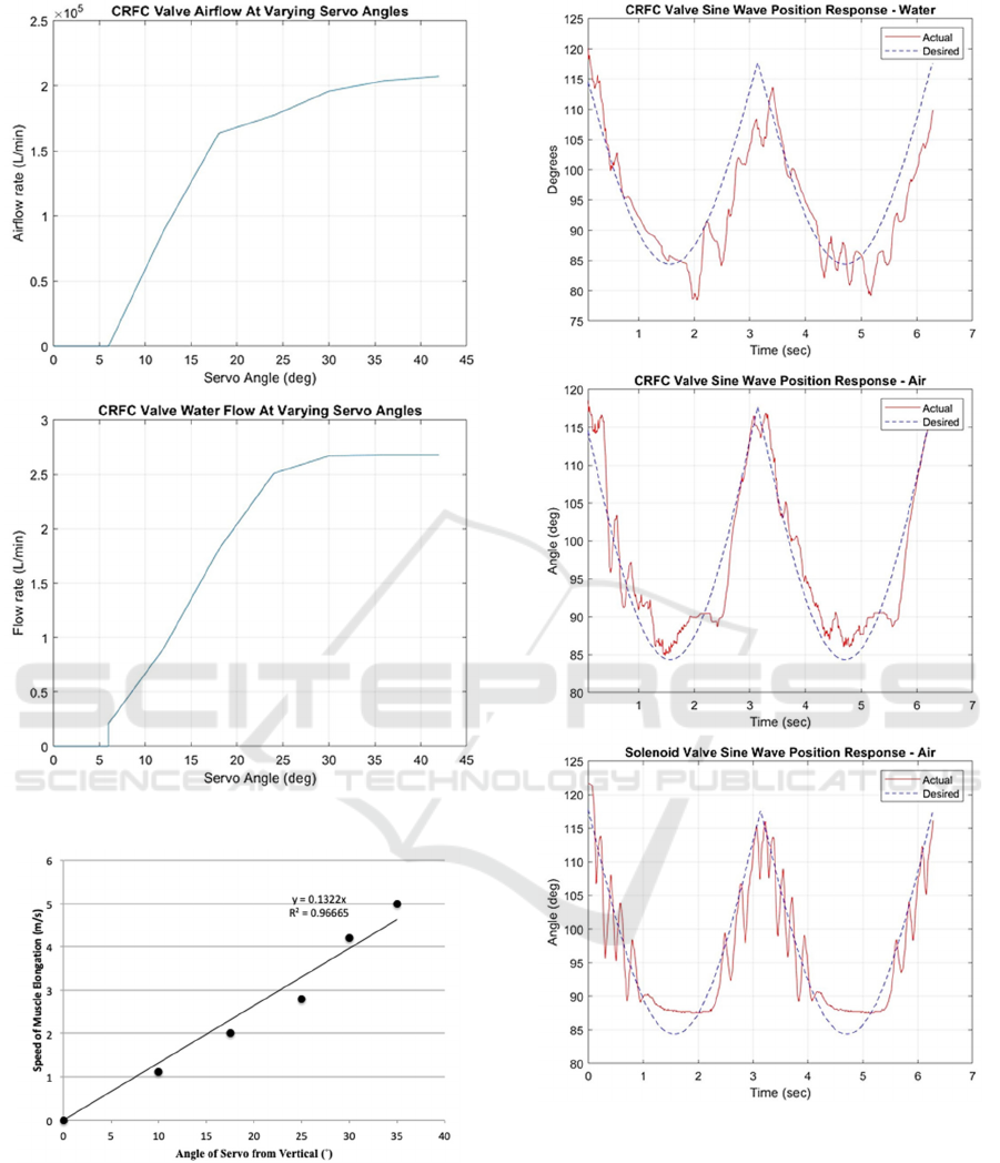
Figure 10: Flow vs. angle; water (bottom) and air (top).
Figure 11: Hydro Muscle speed vs. servo angle.
Figure 12: Controllability tests: water CRFC Valve (top),
air CRFC Valve (middle), air solenoid valve (bottom).
3.4 CRFC Valve: Discussion
The exosuit, addressed in Section II utilized heavy
12cm by 10cm by 2cm on-off flow control modules
[26,27] that had a pre-set orifice size. When the
exosuit was first constructed, these were the most
practical, affordable solution on the market. To
Development of Bioinspired Exosuit Actuated with Hydro Muscles and Novel Compact Robotic Flow Control Valve
47

address already specified limitations of such flow
management system, the CRFC Valve was created.
This new valve is small, lightweight, cost-effective,
and can operate using both air and liquid. The new
CRFC valve takes up only 1/6th of the original valve’s
volume, and has a mass of only 28 grams (i.e. 1/10th
of the original weight). Additionally, the CRFC Valve
exhibits a relatively fast response time with very little
difference between water and air mediums.
Based on reviews of commercially available valves
(ASCO, Engineering Solutions), the quick response
times for fully opening and fully closing of 4-8 mm
inner diameter, commercially available, pilot solenoid
valves operating at ~100 PSI air pressure range from
10ms to 20ms and 20ms to 80ms respectively. In the
case of liquids these ranges are typically 15ms to 30ms,
and 30ms to 120ms respectively. The valves with these
parameters are typically valued at greater than $100
USD.
In comparison, the CRFC valve costs about $10
USD to produce. The full closing and opening times
for the same conditions are approximately 65ms for air
and 70ms for water. Additionally, the CRFC Valve
allows for continuous fine control of flow. The CRFC
Valve’s speed is well suited for wearable robotic
actuation systems, as it takes about 250ms for a skeletal
biological muscle to develop a peak force.
The CRFC flow is reasonably large with
2.5/ and 210
/ for water and air
respectively. The flow can be increased by using
different tube dimensions. The flow results exhibit a 6
deadband angle, which addresses potential servo
inaccuracies and introduces control delays. Before it
saturates, the flow is roughly proportional to valve
angle.
The result of the test relating servo angle to the
Hydro Muscle elongation speed exhibits an
-value
of 0.967. There is a strong linear relationship between
flow rate and servo angle. This largely linear behavior
is a characteristic of an optimized valve design. This
linear control of the flow allows for better control of
the Hydro Muscle than with the original on-off
solenoid valve.
The CRFC Valve operating with air has a more
precise and accurate tracking than the original 5-way
on-off solenoid valve. There was significantly less
oscillation in the CRFC Valve tests when compared to
the original solenoid valve due to the CRFC Valve’s
mechanism preventing sharp, jerky movements. While
both valves had oscillations, the CRFC Valve’s were
mainly due to sensor noise, while the solenoid valves
oscillations were due to the 2-state nature of the valve.
However, with improved sensors and a revised control
scheme, the response of the CRFC Valve could be
drastically improved.
From the response tests of the CRFC Valve, it is
clear that the choice of fluid impacts the response of
the system, however, the valve is still able to follow the
desired trajectories in a smooth and controlled manner.
The main issue in the system operating with water was
the inexpensive diaphragm pump being used. The
pump would frequently turn on and off, hence creating
an oscillatory behavior throughout the system; it is
likely that with improved system components the
results would be more indicative of the valves
capabilities. Additionally, due to the CRFC Valve’s
significantly reduced size and weight, the exosuit has
improved portability.
Due to the precise control over the fluids in the
actuators, the design has potential to create highly
controllable robotic systems.
4 CONCLUSIONS
The bioinspired exosuit strives to be a cost-effective,
fluidly actuated, wearable robotic device that can be
used for physical therapy and/or assistance with
activities of daily living. The bioinspired exosuit has
been designed, manufactured, tested on a lightweight
biomimetic human skeletal model. This initial study
motivated a need for better flow management system,
which inspired the creation of the CRFC Valve.
The CRFC Valve is lighter, more compact, more
controllable, and less expensive than any other similar
valve currently on the market. Now that the CRFC
Valve has been developed, future work will be focused
on constructing a wearable exosuit with the CRFC
Valves. Other applications for the CRFC Valve will
also be explored. The synergy of the CRFC Valve with
the cost-effectiveness, energy efficiency, and excellent
strain properties of Hydro Muscle opens a door into a
new age of very interesting, useful, and
accessible/affordable fluid operated wearable robotics
solutions.
REFERENCES
Arduino MEGA 2560. Arduino. Microcontroller.
Asbeck, A. T., Dyer, R., Larusson, A., and Walsh, C. J.,
“Biologically inspired soft exosuit,” 2013 IEEE
International Conference on Rehabilitation Robotics
(ICORR), pp.1-8, 2013.
Asbeck, A.T., De Rossi, S.M., Galiana, I., Ding, Y. and
Walsh, C.J., 2014. Stronger, smarter, softer: next-
BIODEVICES 2020 - 13th International Conference on Biomedical Electronics and Devices
48

generation wearable robots. IEEE Robotics &
Automation Magazine, 21(4), pp.22-33.
ASCO, Engineering Solutions, Solenoid valves.
https://www.asco.com/ASCO%20Asset%20Library/asco-
solenoid-valves-engineering-information.pdf
Blaya, J.A., and Herr, H.. “Adaptive control of a variable-
impedance ankle-foot orthosis to assist drop-foot gait,”
IEEE Transactions on neural systems and rehabilitation
engineering, 12(1), pp.24-31, 2014.
Bowers, M., Harmalkar, C., Agrawal, A., Kashyap, A., Tai,
J., and Popovic, M.B., Design and test of biologically
inspired multi-fiber Hydro Muscle actuated ankle,
Proceedings of 2017 IEEE International Workshop on
Advanced Robotics and its Social Impacts, March 8-10,
2017, University of Texas at Austin, Austin, TX, USA.
Curran, A., Colpritt, K., Moffat, S., and Sullivan, M.,
“Humanoid Walking Robot,” Major Qualifying Project,
Worcester Polytechnic Insitute, 2018.
Elbow Pneumatic Flow Control Valve. Utah Pneumatic. 1/4
OD 1/8 NPT Push to connect valve.
Exacme 6400-0108BK Treadmill. Exacme. Combo 500W
folding electric motorized treadmill.
Functional Physiological Skeleton Model - Frank - Hanging
Stand, Anatomical Models - Human Skeleton Models.
[Online]. https://www.a3bs.com/functional-
physiological-skeletonmodel-frank-hanging-
stand,p_164_20.html [Accessed: 15-Oct-2017].
Galiana, I., Hammond, F.L, Howe, R.D., and Popovic, M.B.,
“Wearable Soft Robotic Device for Post-Stroke Shoulder
Rehabilitation: Identifying Misalignments” 2012
IEEE/RSJ International Conference on Intelligent
Robots and Systems, October 7-12, 2012. Portugal.
Herr, H., Blaya, J.A., and Pratt, G.A., Massachusetts Institute
of Technology, 2012. Active Ankle foot orthosis. U.S.
Patent 8,287,477
Hoy, M.G., Zajac, F. E., and Gordon, M. E., “A
musculoskeletal model of the human lower extremity: the
effect of muscle, tendon, and moment arm on the
moment-angle relationship of musculotendon actuators
at the hip, knee, and ankle”. Journal of Biomechanics,
23(2), 1990, pp. 157-169.
Hunt, T., Berthelette, C., Iannacchione, G. S., Koehler, S.,
and Popovic, M. B., “Soft Robotics Variable Stiffness
Exo-Musculature, OneTo-Many Concept, and Advanced
Clutches.” In IEEE ICRA 2012 WORKSHOP: Variable
Stiffness Actuators moving the Robots of Tomorrow, St.
Paul, Minnesota, May, vol. 14. 2012.
Kesner, S.B., Jentoft, L., Hammond, F.L., Howe, R.D., and
Popovic. M.B., “Design Considerations for an Active
Soft Orthotic System for Shoulder Rehabilitation” 33rd
Annual International IEEE EMBS Conference, August
30 - September 02, 2011, Boston, USA.
Kurumaya, S., Suzumori, K., Nabae, H., and Wakimoto, S.,
“Musculoskeletal lower-limb robot driven by
multifilament muscles”. Robomech Journal, 3(1), p.18,
2016.
Lewis, C. L., and Sahrmann, S. A., “Effect of Posture on Hip
Angles and Moments during Gait,” Manual Therapy
(20), pp. 176-182, 2015.
Lokomat, Hocoma. Zurich, Switzerland.
Mao, Y., and Agrawal, S.K., “Design of a cable-driven arm
exoskeleton (CAREX) for neural rehabilitation”. IEEE
Transactions on Robotics, 28(4), pp.922-931, 2012.
McCarthy, G., Effraimidis, D., Jennings, B., Corso, N., Onal
C., and Popovic, M.B., “Hydraulically Actuated Muscle
(HAM) Exo-Musculature” in “Robot Makers: The future
of digital rapid design and fabrication of robots” (RoMa)
Workshop, the 2014 Robotics: Science and Systems
Conference, Berkeley, CA, July 12, 2014.
MG90D HIgh Torque Metal Gear. Adafruit. Micro servo.
Miriyev, A., Stack, K., and Lipson, H., “Soft material for soft
actuators.” Nature communications 8.1 (2017): 596.
Moffat, Shannon Marija. "Biologically Inspired Legs and
Novel Flow Control Valve Toward a New Approach for
Accessible Wearable Robotics." Master Thesis,
Worcester Polytechnic Institute (2019).
Olensek, A., and Matjacic, Z., “Adjusting kinematics and
kinetics in a feedback-controlled toe walking model,”
Journal of NeuroEngineering and Rehabilitation (9), pp.
1-12, 2012.
Park, Y.L., Chen, B.R., Pérez-Arancibia, N.O., Young, D.,
Stirling, L., Wood, R.J., Goldfield, E.C. and Nagpal, R.,
2014. Design and control of a bio-inspired soft wearable
robotic device for ankle–foot rehabilitation.
Bioinspiration & biomimetics, 9(1), p.016007.
Pneumatic Electric Solenoid Valve. U.S. Solid. 1/4 5 way 2
position DC 24 V.
Popovic, M. B. 2013. Biomechanics and Robotics, Pan
Stanford Publishing Pte. Ltd., 1
st
edition.
Popovic, M. B. 2019. Biomechatronics, Academic Press,
Elsevier, 1
st
edition.
Pratt, G.A. and Williamson, M.M., 1995, August. Series
elastic actuators. In Intelligent Robots and Systems
95.'Human Robot Interaction and Cooperative Robots',
Proceedings. 1995 IEEE/RSJ International Conference
on (Vol. 1, pp. 399-406).
Saint-Elme, E., Larrier, M.A., Kracinovich, C., Renshaw, D.,
Troy, K., and Popovic, M.B., “Design of a Biologically
Accurate Prosthetic Hand”, IEEE RAS International
Symposium on Wearable & Rehabilitation Robotics
Houston, TX November 5-8, 2017.
SparkFun Triple Axis Accelerometer and Gyro Breakout
MPU-6050. SparkFun. Inertial measurement unit.
Spiderwire Stealth SCS50G-200. Spiderwire. 200yd, 50lb,
Braided fishing line.
Sridar, S., Majeika, C. J., Schaffer, P., Bowers, M., Ueda, S.,
Barth, A. J., Sorrells, J. L., Wu, J. T., Hunt, T. R., and
Popovic, M., “Hydro Muscle - a novel soft fluidic
actuator”, IEEE International Conference on Robotics
and Automation (ICRA), pp4104-4021, 2016.
Streifeneder. “Ortho.lab - Software and systems for video-
based motion analysis.”
Uberhose153. Uberhose. Watering hose.
Ueda, J., Ming, D., Krishnamoorthy, V., Shinohara, M., and
Ogasawara, T., “Individual muscle control using an
exoskeleton robot for muscle function
testing”. IEEE
Transactions on Neural Systems and Rehabilitation
Engineering, 18(4), pp.339-350, 2010.
Development of Bioinspired Exosuit Actuated with Hydro Muscles and Novel Compact Robotic Flow Control Valve
49
