
A Real-time Ultrasound Rendering with Model-based Tissue
Deformation for Needle Insertion
Charles Barnouin
1
, Florence Zara
1 a
and Fabrice Jaillet
2 b
1
Universit
´
e de Lyon, CNRS, Universit
´
e Lyon 1, LIRIS, SAARA Team, UMR5205, F-69622, France
2
Universit
´
e de Lyon, IUT Lyon 1, Computer Science Department, F-01000, Bourg-en-Bresse, France
Keywords:
Ultrasound Rendering, 2D Texture, Haptic Devices, Physically based Tissue Deformation, Needle Insertion.
Abstract:
In the course of developing a training simulator for puncture, a novel approach is proposed to render in real-
time the ultrasound (US) image of any 3D model. It is combined with the deformation of the soft tissues (due
to their interactions with a needle and a probe) according to their physical properties. Our solution reproduces
the usual US artifacts at a low cost. It combines the use of textures and ray-tracing with a new way to efficiently
render fibrous tissues. Deformations are handled in real-time on the GPU using displacement functions. Our
approach goes beyond the usual bottleneck of real-time deformations of 3D models in interactive US simula-
tion. The display of tissues deformation and the possibilities to tune the 3D morphotypes, tissue properties,
needle shape, or even specific probe characteristics, is clearly an advantage in such a training environment.
1 INTRODUCTION
Ultrasound (US) is a radiation-free, non-invasive and
real-time imaging medical device. Widely used in
clinical practice, it is a mechanical wave propagating
in fluids and solids generally at 20 kHz. Multiple tis-
sue interactions create the final image, such as spec-
ular reflection and refraction, absorption and scatter-
ing. Relatively cost-effective, it is relevantly used for
both diagnosis and image-guided interventions (Heer
et al., 2004). Nevertheless, extensive training is re-
quired to acquire and interpret ultrasound images, es-
pecially when paired with the insertion of a needle.
For example, the puncture necessitates spatial rea-
soning, hand-eye and left/right hand coordination, all
skills developed through extensive training.
In the rheumatology domain, a relevant training
simulator for needle insertion has to enable students
to learn how to puncture from multiple points of
view, and to identify tissues which properties may
differ from a patient to another, or when tissues are
inflamed. Moreover, the training environment has
to provide interactive and accurate forces feedback
through haptic devices: during puncture, the rheuma-
tologists adapt their gesture to the deformations in-
duced by the probe and needle movements. Thus,
a
https://orcid.org/0000-0002-0118-7204
b
https://orcid.org/0000-0002-7330-8116
two challenges emerge to develop such a simulator:
(i) render a realistic enough ultrasound image in any
probe/tissues configuration, embedding all the prop-
erties to clearly identify the biological tissues; (ii)
provide real-time interactions between the soft tissues
and the medical devices through force feedback and
visible deformations on the ultrasound image.
In this paper, we propose a new strategy to address
these two points. We will describe our proposed solu-
tion for ultrasound rendering, haptic forces feedback
and display of tissues deformation on the ultrasound
images. All the components of our solution are linked
and embodied in a coherent framework. At the end,
our approach based on the GPU permits:
• a real-time ultrasound rendering including tissues
fibrosity according to their geometrical properties.
We used an original texture-dependent oriented
blur to enhance realism.
• a visualization of tissues deformation directly on
the ultrasound image. We used some displace-
ment functions accounting for the tissues proper-
ties and the interaction forces between the haptic
devices and the 3D scene.
Our solution has been designed to be easily trans-
ferable to multiple medical cases and areas of interest,
such as the shoulder or ankle joints. It combines tech-
niques from Computer Graphics rendering and Vir-
tual Reality in a complementary way to provide re-
Barnouin, C., Zara, F. and Jaillet, F.
A Real-time Ultrasound Rendering with Model-based Tissue Deformation for Needle Insertion.
DOI: 10.5220/0008947302350246
In Proceedings of the 15th International Joint Conference on Computer Vision, Imaging and Computer Graphics Theory and Applications (VISIGRAPP 2020) - Volume 1: GRAPP, pages
235-246
ISBN: 978-989-758-402-2; ISSN: 2184-4321
Copyright
c
2022 by SCITEPRESS – Science and Technology Publications, Lda. All rights reserved
235

alistic visual and touch sensations at the same time.
Ray-tracing and texture manipulation provide accu-
rate enough tissue rendering for a real-time simulator,
while the collision and haptic algorithms are suitable
for a fast update necessary for a smooth touch feeling.
2 STATE OF THE ART
This section presents previous work on ultrasound
rendering and simulation of needle insertion. Both
are combined to provide realistic tissue deformations
and haptic feedback within an ultrasound view.
Ultrasound Rendering. The techniques to create US
image can be separated in two approaches: interpola-
tion of real images or generation of realistic images.
The first approach uses pre-recorded 3D ultra-
sound volume, generally acquired with a 3D probe, or
by combining multiple 2D slices. In some cases, the
3D volume can also be reconstructed from Computed
Tomography (CT scan) or MRI acquisition. Dur-
ing the ultrasound rendering simulation, the volume
is sliced along the plane created with the ultrasound
probe. With this approach, in (Magee and Kessel,
2005), an augmented reality simulator matched a real
CT scan with a mannequin body, whereas the probe
was calibrated to find the location and orientation
of the ultrasound plane to slice the volume. Later
on, they improved the image quality with 3D tex-
tures obtained from real images (Magee et al., 2007).
In (Ni et al., 2011), a biopsy simulator was embedding
several ultrasound volumes scanned with a dedicated
probe and stitched together to form a panorama. This
panorama is then resampled to match a previously ac-
quired CT scan of the same volume. Spacial trans-
formations may be applied afterwards, to create res-
piratory motion for example. In (Vidal et al., 2008),
an ultrasound guided needle puncture simulator with
patient specific CT scan is proposed, which also re-
quires an acquisition phase and remains very patient-
dependent. They added several post-processing ef-
fects like shadows, but did not implement tissue de-
formation. In (Goksel and Salcudean, 2009), they
used 3D ultrasound volumes matched to a 3D elas-
ticity model to perform a fast B-Mode ultrasound im-
age in deformable tissues. While being realistic for
obvious reasons, this class of approach imposes con-
straints on the model, which needs to roughly match
the database and to be created for every considered
joint. Moreover, it requires to create a 3D volume for
each new case, such as specific location of inflamma-
tory tissues or patient specific geometry or morphol-
ogy (aged or fat inflamed shoulders considerably dif-
fer from a healthy and young one). The specificity of
the probe (field of view, frequency, area of effect, etc.)
is also imposed by the acquisition probe.
The second approach to synthetic ultrasound im-
ages consists in simulating the ultrasonic wave prop-
agation in the media, with accurate models of the
probe, tissue scatterers, and interface models. Usu-
ally, generating a single frame is simply too time con-
suming for real-time applications. The older models
may take up to several hours (Bamber and Dickinson,
1980; Jensen, 1991). However, new approaches are
getting closer to real-time, such as (Marion and Vray,
2009), where a linear convolution model and a 3D set
of moving scatterers were used, combined with bet-
ter hardware. Others physical ray-tracing methods us-
ing GPU such as presented in (Mattausch and Goksel,
2016; Burger et al., 2013) are seen as very promising
despite a loss of performance while dealing with tis-
sue deformations. They used a combination of convo-
lution and ray-tracing to create their render. Another
interesting idea was presented in (Law et al., 2011)
to render ultrasound images on deformable meshes,
using two opposite rays for each pixel that needs to
be rendered, one of them going towards the probe.
They register the traversed materials to deduce the
pixel color, and thus are able to create effects like at-
tenuation. However, performances of this approach
are not compatible with the requirements of a training
simulator, especially when the probe is moving con-
tinuously. Finally, the ray-tracing methods don’t take
tissue fiber into account: as the number of surfaces
goes higher, it would increase the number of bounces
and thus the calculus time.
To go beyond the limitations of both approaches,
such as the rigidity of 3D data volume for the former
and computation time for the latter, we propose a
novel approach combining the use of textures and
ray-tracing to render ultrasound effects like shadows,
speckle, and fiber orientation. Moreover, in the
context of the development of a training medical
simulator, real-time computation, as well as the pos-
sibility to tune the 3D models, the physical properties
of tissues, or the probe characteristics (field of view,
attenuation, etc.) are important points to consider.
Needle Insertion Simulation. Modeling techniques
for puncture also face the accuracy vs real-time trade-
off. Soft tissue cutting, due to the needle insertion,
involves three types of force: frictional, elastic, and
actual cutting forces. However, the cutting force is of-
ten modeled as a constant acting at the tip of the nee-
dle, and no actual tissue cutting is performed for per-
formance reasons. In a review on cutting mechanics
and techniques (Takabi and Tai, 2017), the cohesive
zone model is seen as the most promising technique,
though requiring to set up the cohesive zone before
GRAPP 2020 - 15th International Conference on Computer Graphics Theory and Applications
236

the cutting. Moreover, the step-by-step remeshing,
used to prepare the zone, may be time-consuming,
and the simulation itself is not performed in real-time.
Yet, needle insertion modeling for real-time applica-
tion has been presented in (Abolhassani et al., 2007),
which aims to address the modeling of the force as
well as the needle path.
In one of the precursor works in puncture model-
ing (DiMaio and Salcudean, 2003), the force distri-
bution is estimated along the shaft and a 2D model is
proposed for force/displacement relationship. Later,
Okamura et al. investigated the in vitro needle forces
using sensors, and presented models for cutting, fric-
tion and elastic forces during puncture (Okamura
et al., 2004). The strength of those models is that they
are simple enough for real-time applications. A new
method was presented in (Duriez et al., 2009) for the
insertion of flexible needle using constraint models.
They achieved a real-time simulation with deformable
needle and tissue, while adding effect like steering.
However, only a simple model was presented, and
there is no evidence the method will keep working
with more complex ones.
(Crouch et al., 2005), and later on (Gao et al.,
2013) chose to study the tissue deformation in regard
of time and insertion velocity. The former focuses on
the insertion force once the needle is inside the tis-
sue, while the latter insists on the deformation of the
surface during puncture. Both studies are of partic-
ular interest: assuming the needle velocity being ap-
proximately constant during puncture, they can link
tissue deformation and needle insertion with a simple
mathematical function. Both authors assure a good
approximation of force and deformation, even if the
fidelity of the relaxation phase could be improved.
In our approach, the force feedback, due to the
needle insertion in tissues, is calculated without
changing the topology of the meshes involved in the
3D scene. Our solution is based on the use of dis-
placement field models allowing us to handle de-
formation according to both physical properties (the
force intensity) of the tissues and the organ shape (via
the geometric mesh). It allows us a real-time display,
and an accurate force model compatible with haptic
requirements.
3 GENERAL APPROACH
To propose a relevant training simulator of needle
puncture, one of the challenges remains in generat-
ing an interactive 2D view of the 3D scene with a re-
alist ultrasound rendering which must exhibit the tis-
sues deformation involved by the manipulation of two
haptic devices (simulating the probe and the needle).
At the beginning of each time frame, the first step
consists in computing a 2D slice of the 3D scene ac-
cording to the probe position. To that aim, a new sur-
face is created for each 3D mesh of the scene using
the Capping Clipped Solids method (McReynolds and
Blythe, 2005, chapter 16). This OpenGL based solu-
tion enables a fast computation of the slices, and the
new surfaces hence created will serve as support for
the effects during the rendering pass, to integrate the
tissues deformation and create the final ultrasound im-
age. Moreover, the 2D slice is rendered in the same
render pass as the 3D scene, which means both can
be displayed concurrently without performance loss.
This enables a nice two-views display inside the med-
ical simulator Next. Fig. 1 illustrates our pipeline
strategy of creating, in real-time, a relevant ultrasound
rendering with tissues deformation.
Haptic rendering
(section 5)
US rendering
(section 4)
Tissue deformation
(section 6)
US rendering with
deformation
(section results)
f
s
,f
c
,f
f
Figure 1: Our pipeline to obtain an ultrasound image of our
3D scene during the manipulation of the two haptic devices.
Ultrasound Rendering (see section 4). The ultra-
sound view requires two steps. Firstly, we deal with
a solution based on an ultrasound database limited
to textures, to compute the ultrasound rendering on
the 2D slice. Note that, no complete pre-recorded
ultrasound volume is required. Secondly, some extra
treatments are performed to consider the orientation
of the tissues (with an original way to show fiber
orientation for tendon using a texture-dependent
oriented blur) or to add artifacts (like shadow or
reflection) resulting from the manipulation of a
probe. This approach enables the generation of the
ultrasound view of any joints (shoulder, knee) in
all directions according to the manipulation of the
probe. Moreover, it only requires a few number of
real ultrasound images.
Haptic Rendering (see section 5). To reproduce the
sense of touch and to improve the realism of the
simulator, we provide haptic feedback of the probe
and of the needle used during puncture. As these
devices exhibit distinct behavior, the force-feedback
algorithm would differ: the probe only experiences
contact, while the needle goes through contact and
A Real-time Ultrasound Rendering with Model-based Tissue Deformation for Needle Insertion
237
insertion. Thus, frictional, elastic and cutting force
are modeled for the needle, which is also path
constrained with a tunnel effect. While the forces
calculation is already well-known, the precision of
our collision algorithm and our tunnel effect allow
us to easily transfer the force information to produce
accurate visual deformations due to the interactions.
Tissue Deformation (see section 6). The ultrasound
view must display the deformations undergone by
tissues due to the needle insertion during the puncture
gesture, as well as probe/tissue interactions. To that
end, we use the haptic devices feedback and we
define two displacement functions that link the force
to the displacement of the surrounding tissues. Then,
the calculus of these deformations is performed on
the GPU to create a specific output image. Finally,
this 2D output image will be used to integrate
these deformations into the ultrasound view. This
approach, which is based on the deformation of the
2D image (rather than the simulation of 3D mesh
deformations), enables us a real-time rendering of the
tissues deformation.
Fig. 2 gives an illustration of the modules in our
framework and the communications between them.
Scenes
(Simulation goal)
3D meshes,
physical properties
US textures
Collision detection
(section 5)
Force model
(section 5)
Device position
Collision detection
(section 5)
Force model
(section 5)
Device position
User
VAO/VBO
Shadow testing
Clipping
Texturing
Displacement
(section 6)
US effects
(section 4)
Final output
(section results)
Needle Probe
Hand Hand
Haptic thread
Database
Render thread
Monitor
Figure 2: The modules of our framework.
4 ULTRASOUND RENDERING
In this section, we will detail our solution to create an
US rendering of a 3D scene in real-time. It deals with
ultrasound texture and additional treatments to further
integrate usual ultrasound artifacts (Law et al., 2011).
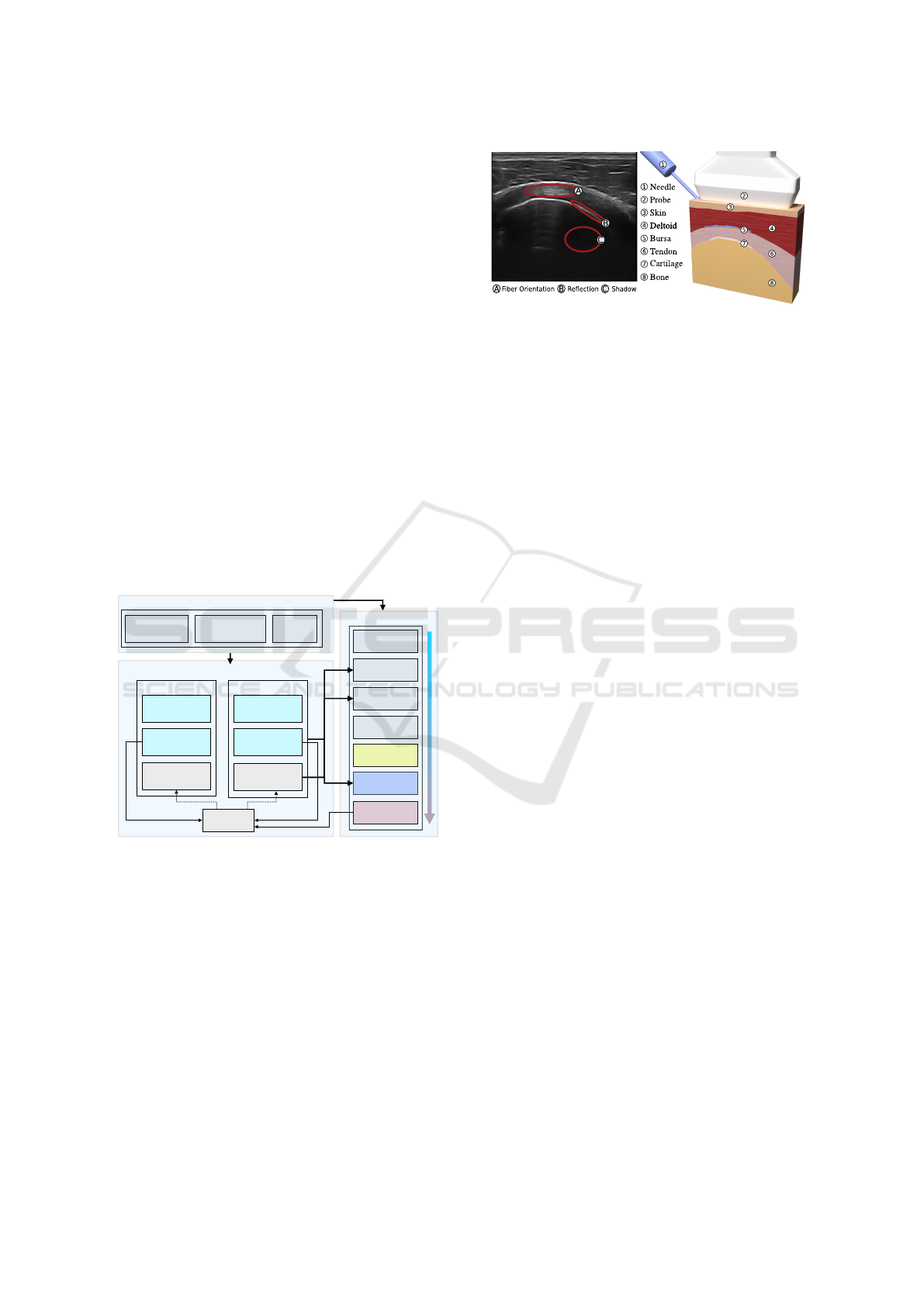
Creation of Our 3D Scene. A simplified scene
based on a young and healthy shoulder will serve to
illustrate our rendering process. To create this scene,
all tissues but subcutaneous fat were segmented from
a reference US image. Then, the layers were extruded
and turned into 3D meshes. At the end, it contains
Ultrasound reference image
Figure 3: 3D view of the shoulder scene made from a US
reference image. The probe and the needle have been added.
4,004 tetrahedral elements for all the involved tissues
(Fig. 3(3-8)). Next, our US rendering process runs
in several steps, as illustrated on Fig. 4. It starts
from the 2D slice of the 3D scene (Fig. 4a) on which
several effects (reflection, shadow, attenuation, noise,
blur, orientation) are added to obtain the US view
(Fig. 4f).
2D Slice with Diffuse Color. The process starts from
Fig. 4a with the 2D slice of our 3D scene (obtained
according to the probe position). The 2D surfaces
created by the Capping Clipped Solids method were
given a diffuse color, except for the deltoid. Indeed,
for thick tissue (like deltoid), we can directly apply a
texture acquired from the reference image (Fig. 3(4)),
by selecting a zone with a representative pattern
for the tissue, and using a texture synthesis algo-
rithm (Harrison, 2001). Thus, we use the similarity
of the fibrous pattern in thick muscles for a given
orientation to fill a texture data bank from reference
images, and use those textures as a basis for the US
images of any thick muscle. Two orientations were
considered: lateral and longitudinal (respectively
perpendicular and parallel to the US plane), due to
differences in patterns. The diffuse color given to
each of the other tissues is its target mean color in
the final render, at the exception of the bone tissue,
whose white color is the the reflection one.
Reflection and Shadow. Reflection and refraction
occur at the boundary of two media. In fluid/fluid
interfaces, the reflection ratio increases with the dif-
ference of acoustic impedance between the media.
The intensity reflected I
r
at the interface from an
incoming intensity I
i
is defined according to the
acoustic impedance Z
1
,Z
2
of each media with: I
r
=
I
i
((Z
2
− Z
1
)/(Z
2
+ Z
1
))
2
.
Visually, a bright area appears at most of tissue in-
terfaces (skin/muscle, muscle/tendon - Fig. 3(B)) due
to this reflected intensity. For fluid/solid interfaces,
when the ultrasound wave encounters a bone, most
of the energy will be reflected. As a result, a darker
area/shadow (Fig. 3(C)) appears below the bone sur-
face, with a bright area on the bone interface itself.
GRAPP 2020 - 15th International Conference on Computer Graphics Theory and Applications
238
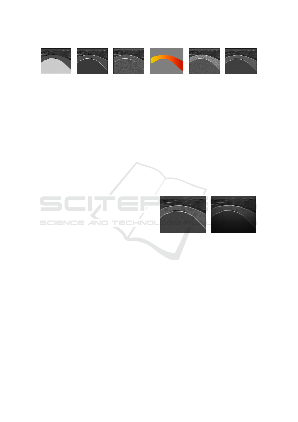
(a) 2D slice (b) = (a) + ref./sh. (c) = (b) + noise (d) fiber orientation (e) = (c) + (d) (f) = (b) + (e)
Figure 4: Illustration of the rendering pass effects to generate an US image. Contrast has been modified for a better view.
To create both effects at the same time, a typical
depth map is filled into a texture, before any other ren-
der pass (the US probe acting as a spotlight). This
depth map contains information relative to the dis-
tance of the surfaces of objects to the probe. It pro-
vides feedback regarding which parts are lying under-
neath bones, for example. Later on, a ray-tracing is
performed to trigger shadows in appropriate places.
Let’s note that a small bias was added to the depth
testing to acknowledge the reflection phenomenon.
While inside this bias, the render appears brighter.
This method allows us to create both the reflec-
tion and shadow rendering in one step for fluid/solid
interfaces. For a fluid/fluid interface, only the bright
area is rendered: e.g. tendons appear as hyperechoic
(bright) but get no shadow. In our example, applying
these effects on Fig. 4a leads to Fig. 4b.
Attenuation. When the US wave propagates through
the tissues, the acoustic pressure undergoes an attenu-
ation of its global amplitude. Attenuation gathers two
ultrasound phenomena: scattering and absorption.
Scattering. The scattering effect results from the
interaction of the wave with the small particles or
defaults in the biological tissue. Their physical
properties are different enough from the surrounding
medium to lead to the emission of a secondary wave.
It creates the speckle effect in the US images, which
is computationally intensive to recreate accurately.
In our rendering, the speckle is approximated by a
Perlin noise: from Fig. 4b, we obtained Fig. 4c.
Absorption. This effect depends on the frequency f of
the probe, the biological tissue characteristics and the
distance to the wave emission point. With attenuation
coefficient α and depth z , the attenuation intensity I
a
from an incoming intensity I
i
is defined by:
I
a
= I
i
· 10
−αz f /20
. (1)
Visually, it generates darker pixels as the wave
propagates further. A non physically-realistic but
cost effective and accurate enough visual effect can
be achieved with the help of the same ray-tracing
as in the shadow rendering pass. Indeed, knowing
the distance between the pixel to be rendered and
the probe, it is enough to use only the average soft
tissue attenuation for each tissue in the scene. The
attenuation effect is added at the end of the rendering
process: with Fig. 5a (identical to Fig. 4f), we
obtained Fig. 5b (using α = 0.54 db/(MHz.cm)).
Fiber Orientation. As previously explained for del-
toid, longitudinal and lateral 2D textures are ex-
tracted and synthesized beforehand from real ultra-
sound recording to consider the orientation of some
biological thick tissues like muscles. Then, the right
texture blending ratio is computed relatively to the
tissue orientation with the probe. However, the tex-
ture synthesis failed for thin tissues (like tendons -
Fig. 3(A-6)) since the input data are too scarce. A
way to achieve the desired visual orientation would
be to model all lines inside the fibrous model. How-
ever, this would force us to create numerous lines in-
side each fibrous tissue prior to the rendering pass,
thus dramatically reducing performances. Instead, we
proposed a new method that we called oriented blur.
(a) w/o absorption (b) w/ absorption
Figure 5: US image without (a) or with (b) absorption.
Pre-computation. The first (pre-computed) step is to
retrieve the orientation of the fiber. It is calculated
for all vertices thanks to the specific geometry
of tendon-like tissue. Indeed, tendons present
a curved cylindrical shape, in which the fibrous
lines follow the direction of the curve. Thus, the
direction is set by the smallest principal curvatures
via quadratic fitting (Panozzo et al., 2010). This
direction is then normalized and stored as a 3D vector.
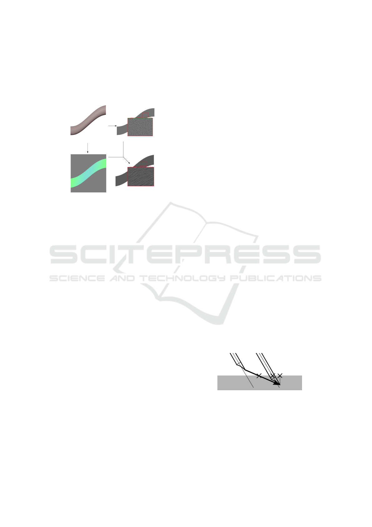
Then, during the generation of the ultrasound
view, the oriented blur used for thin tissues works in
two phases (see Fig. 6).
First GPU pass. The considered 3D tissue (Fig. 6a)
is clipped in the ultrasound plane according to the
probe position, and its surface is colored according
to the orientation of the fibers (Fig. 6b). For our 3D
scene, Fig. 4d displays the orientation of the fibers
of the tendon. This created image will be readable
by the GPU later on. For this result, the normalized
A Real-time Ultrasound Rendering with Model-based Tissue Deformation for Needle Insertion
239
three-dimensional curvature direction is mapped into
the three-dimensional (RGB) color space. Hence, the
gray color corresponds to the null vector. Since it ac-
counts for the orientation of the probe, this step can-
not be pre-calculated.
(a) (c)
(d)(b)
Figure 6: Oriented blur method: (a) a 3D tendon-like tissue
is transformed into (d) a fibrous tissue on the 2D US view
using (b) its RGB curvature map and (c) its noisy 2D image.
Second GPU Pass. The created image (Fig. 6b) is
used as an input to post-process the noisy image
(Fig. 6c) to create the oriented blur (Fig. 6d): an
inverse mapping on the input image gives the blur
direction for each pixel of the noisy image. Then,
a 1D convolution kernel to calculate the mean of 9
pixel values in the direction is used.
This technique fully uses the noise coming from
the non homogeneous properties of the tissue (for a
tissue with a plain original color, the oriented blur
would not change the color of the pixel). Let’s note
that some US images are also being subject to a more
classic radial blur. While this effect is more noticeable
in abdominal ultrasound where the probe will scan for
deep tissues, the distortion of the bottom part of the
US image is still present in the reference image.
To achieve this, the image from Fig. 4c is
post-processed to be rendered multiple times with
radial offset. The center of rotation is given by the
ultrasound probe, and the higher the angle, the less
sharp the image is rendered. For our 3D scene, both
the oriented and radial blur can be seen in Fig. 4e:
the radial blur effect is more noticeable at the bottom
of the picture, while our oriented blur effect is only
present in the tendon.
Final US Image w/o Absorption. To end the render-
ing pass, the blurred picture (Fig. 4e) was mixed with
the image obtained with the reflection and shadow ef-
fects (Fig. 4b) to create the final picture (Fig. 4f). See
Fig. 5b for the same final image with absorption.
5 HAPTIC RENDERING
As previously said, two haptic devices were inte-
grated in our framework. They simulate the manip-
ulation of the needle and the probe to give the user
the sense of touch thanks to forces applied to the de-
vices. To get a smooth haptic feedback, the contact
forces must be updated at around 1,000 Hz. As a
result, the force feedback algorithm runs in its own
thread for both the needle and the probe. Further-
more, their behaviors differ enough to handle them
separately within the simulator (see Fig. 2): the probe
interacts with the surface skin and supplies the plane
for the ultrasound rendering, while the needle pro-
vides puncture forces and interacts with all tissues.
In this section, we will present the force feedback
algorithms for both devices. The generated forces
presented here will be used in the next section to
create the tissue deformation in the ultrasound view.
Collision Detection. The first step in haptic rendering
is the detection of the collision between the haptic de-
vice and the objects in the 3D scene. We use the same
collision thread for both the needle and the probe, as
long as the needle does not pierce the first layer of an
object. Usually, the collision is detected after it al-
ready occurred, by using volumes interpenetration or
by checking if the haptic point is inside an object.
For example, Fig. 7 illustrates the collision detec-
tion with a needle having a velocity v. A collision
point is calculated afterward, using the minimal dis-
tance to surface (leading to point C), or the intersec-
tion of the needle shaft and the surface (leading to
point B). However, it means that the real collision
point is actually never registered, which could gen-
erate accuracy errors in its exact position if the needle
is moving before registration. While this inaccuracy
may be fine for the sole haptic thread, the visualiza-
tion of the deformation that depends on this collision
point would suffer: an offset could appear between
the needle and the deformed tissues.
A
B
C
v
Figure 7: Collision point detection using a ray-casting fol-
lowing the velocity v. A is our detection point, B is the
detection point along the shaft, C is the detection point with
minimal distance to the surface of the virtual object.
To prevent this, we use a ray-casting method
and a Bounding Volume Hierarchy on the surface
triangles to detect precisely the collision point, even
though this level of precision will mostly be used
GRAPP 2020 - 15th International Conference on Computer Graphics Theory and Applications
240

for the force feedback and accuracy of the needle.
Below a critical distance between the device and the
triangular surface of the virtual object, a collision
point is created (and constantly updated) by taking
into account the direction of the device’s velocity
(leading to point A). Then, barycentric coordinates
in the detected triangle of the collision point are
stored, along with the normal of the triangle. This
information allows us to detect whether the device is
above or touching the object during haptic rendering.
After that, the behaviors of the devices naturally
differ when they are moving below the plane contain-
ing the detected triangle.
Probe Haptic Rendering. During the penetration of
the surface plane by the haptic device, a classic God-
Object (Zilles and Salisbury, 1995) is created for the
probe. It is constrained to remain above the plane, to
avoid unwanted display with the probe penetrating the
tissues.
Then, to get the haptic rendering of the probe, a
simple stiffness force is calculated based on the elas-
tic properties of the biological tissue, characterized
by a stiffness K. This force f
s
is normal to the probe
and depends on the distance x between the haptic
interface and the God-Object, with: f
s
(x) = Kx n,
where n is the unit vector following the normal of
the collided triangle, K = 0.5 N/mm for the skin (Ni
et al., 2011). The force is null above the tissue.
Moreover, as transmission gel is applied between the
skin and the probe, the tangential part of the friction
force is kept to 0 N. As a result, the probe can move
freely on the object surface (and small friction force
may be added on demand).
Needle Haptic Rendering. During insertion, the nee-
dle involves several force models and may go through
multiple tissues. We followed Okamura which thor-
oughly studied this phenomena for liver tissue (Oka-
mura et al., 2004). Let f
s
, f
c
, f
f
be the forces due to
stiffness, cutting and friction, respectively. Let x be
the distance between the puncture point and the tip of
the needle. The global force f
g
along the needle shaft
(with u its corresponding unit vector) is defined by:
f
g
(x) = f
s
(x) + f
c
(x) + f
f
(x).
Stiffness Force. During the pre-puncture step, the
stiffness force intensity kf
s
k is steadily increasing un-
til the puncture occurs (i.e. as long as kf
s
(x)k < f
p
,
with f
p
the intensity of the necessary force to punc-
ture the interface). At this point, a sharp resistance
loss is detected involving kf
s
(x)k = 0 until a new in-
terface is met. Following Okamura, we chose to ap-
proximate the pre-puncture stiffness force f
s
with a
second-order polynomial leading to: f
s
(x) = (K
1
x +
K
2
x
2
) u, where K
1
,K
2
are parameters chosen accord-
ing to tissues. Even if this force modeling is vastly
used, specific parameter data per tissues are rarely
given. Indeed, even in (Okamura et al., 2004), those
parameters differed for the same tissue between tests.
This problem has been tackled in a survey (van Ger-
wen et al., 2012): without massive experimental data,
the only option is to trust the haptic sense from multi-
ple experts to tune the parameters K
1
,K
2
according to
their own feedback sensation during their experiment
on the simulator.
Cutting Force. After puncture, the cutting force is in-
volved to slice through the tissue. It combines the
fracture force needed to create the path for the needle,
and the stiffness force of the tip of the needle on the
tissue. It is usually isolated by puncturing the exact
same path twice and subtracting the two global forces.
The cutting force is approximated by a constant, if the
needle velocity is not zero, with: f
c
(x) = f
c
u.
Friction force. A wide number of friction models ex-
ists (Yang et al., 2018). Following (Okamura et al.,
2004), a modified Karnopp model is used. For more
information, we advise to see the corresponding arti-
cle.
Tunnel Effect. In addition to the usual forces in hap-
tic needle insertion, we constrain the needle on a path
during the puncture (see Fig. 8). It serves the purpose
of improving the force feedback realism with the ad-
dition of a force perpendicular to the needle shaft.
P
1
P
2
P
0
2
x
f
d
Figure 8: Constraint points and tunnel effect.
The first constraint (P
1
) is the skin collision point.
It is acting as a ball joint combined with a sliding part.
The needle can only slide at the collision point and no
tangential movement is allowed. While right under
the skin surface, the user is free to rotate the needle
to adapt his direction path. But as soon as the user
is exceeding a given depth (P
0
2
) or when another tis-
sue is punctured (P
2
), a new constraint is created. The
two combined constraints create a linear path that the
needle will be constrained to follow. Any deviation
creates a force feedback f
d
simulating the elastic be-
havior of the tissue with the same stiffness K. This
force is the only one perpendicular to the needle shaft
direction. It is defined by:
f
d
= −
K
l
x
x − (x · P
1
P
2
)
P
1
P
2
||P
1
P
2
||
2
, (2)
with x the vector of length x between P
1
and the tip
A Real-time Ultrasound Rendering with Model-based Tissue Deformation for Needle Insertion
241
of the needle, l the full length of the needle. The
first constraint P
1
is of significant importance, as it
will dictate the overall behavior of the needle (hence
the need for precision in the collision thread). This
constraint is linked to the collided triangle and must
be updated during any displacement or deformation
of the considered triangle.
Furthermore, when multiple layers of tissue are
punctured, the force is the sum of the combined ef-
forts of the tissues. For each tissue, the friction force
is weighted by the needle length traversing it. Note
that stiffness and cutting forces only appear at the
layer of the needle tip (and that the stiffness force will
disappear as soon as no layer interface is intersected).
6 TISSUE DEFORMATION
SHADER
The last step consists in taking into account the veloc-
ity and the force feedback of the two haptic devices
in the rendering process. Indeed, the challenge is
to visualize the tissue deformation in the ultrasound
view during gesture. We detail here our original
solution based on displacement fields.
General Approach. The force feedback and velocity
of the needle/probe can be linked to the displacement
of the surrounding tissues by simple equations.
This approach is based on observation and function
fitting (Gao et al., 2013; Crouch et al., 2005). Then,
the 3D displacement function is directly mapped to
the 2D image. It avoids the 3D physical simulation
of soft tissues and interactions with medical instru-
ments, that is barely compatible with real-time.
Rendering Pipeline. In our rendering, there are two
phases to obtain the deformations in the US view:
(i) the 2D ultrasound is rendered into an image (see
Section 4); (ii) this image is displayed on the screen.
However, between these two steps, post-processing
effects may be applied on the GPU.
Let’s consider a pixel P of the 2D image with
basic coordinates (u,v). With no additional effect,
the screen exactly displays the image of the rendered
scene. Now if we want to render the pixel P with an
offset given by a displacement function d, we only
have to apply this displacement at P. Thus, we obtain
its new position d(P) = P
0
of coordinates (u
0
,v
0
). A
heatmap is often used to highlight the displacement
intensity (Fig. 10b or c, with a blue-red scale).
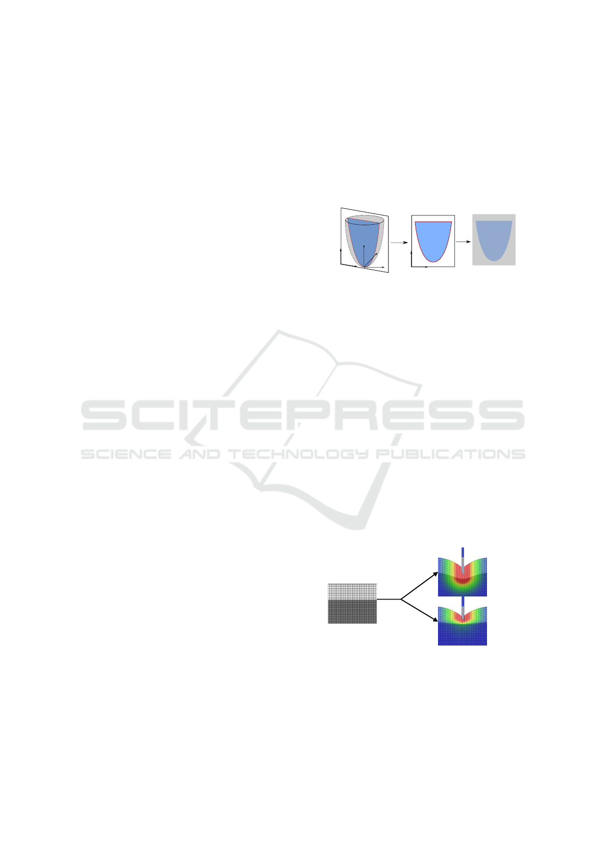
The first step consists in defining the 3D displace-
ment function (noted d(x,y,z) in the world space) cor-
responding to the wanted effect (needle insertion or
probe contact); then, the 2D section corresponding
to the ultrasound plane is retrieved and we apply the
corresponding displacement (noted d(u,v) in the im-
age space) on each pixel. Note that the displacement
function is first computed in 3D, allowing us to see
the influence of the needle on the tissues, even if the
needle itself is not visible in the 2D plane. At the end,
the conversion (much like for the orientation blur pro-
cess) transforms the sectioned deformation function
into a texture readable by the GPU (see Fig. 9).
x
z
y
d(x, y,z)
d(u, v)
v
u
RGB
v
u
Figure 9: (i) The displacement function d(x,y,z) is defined
in the 3D world space. (ii) It is transformed in d(u,v) in the
US image space. (iii) The corresponding texture is stored.
To improve realism, we consider several elastic
behaviors of soft tissues. To illustrate our process,
Fig. 10 presents an example for one section of a sim-
ple 2-layered 3D scene, where a texture grid was
added to better follow the displacement. The Young
modulus E of each tissue is given by its gray value.
Each pixel of the image (Fig. 10a) is moved follow-
ing the value of the displacement function, which de-
pends of the Young modulus. Moreover, a mean value
with neighbor pixels is performed to ensure displace-
ment continuity at the interface between two highly
different values of E. At the end, the difference could
be appreciated when using a single (Fig. 10b) or sev-
eral values (Fig. 10c) of E. Under normal conditions,
the texture grid is replaced by the US render and the
Young modulus information is given by a 2D slice im-
age with a gray shading for each tissue (calculated and
stored at the same time as the diffuse color - Fig. 4a).
E
1
E
2
E
1
= 0.5 N/mm
E
2
= 0.5 N/mm
E
1
= 0.5 N/mm
E
2
= 5 N/mm
(b)
(c)
d(u,v,E)
(a)
Figure 10: Displacement function d(u, v,E) applied on im-
age (a) resulting to image (b) or (c) according to E value.
At this point, the issue is to find fitting and
configurable displacement functions d(x, y,z, E) in
the world space to simulate the deformation due to
the needle insertion and the probe according to the
elastic behavior of the tissue.
GRAPP 2020 - 15th International Conference on Computer Graphics Theory and Applications
242

Displacement Due to the Needle. The deformation
due to the needle can be decomposed into two parts:
(i) the skin deformation before and during puncture;
(ii) the inner tissues deformation after puncture.
Skin Deformation. Intensive work on the deformation
of the skin has been made by Gao et al. (Gao et al.,
2013). Even though the experiment took place with
an artificial tissue and at fixed velocity of 2.5 mm/s, it
shows a relationship between the needle displacement
and the deformed volume of the skin. We used those
results to simulate the deformation of the skin and
subcutaneous tissues during elastic deformation due
to the stiffness force.
Inner Tissues Deformation. The deformation of
subcutaneous tissues is only visible in the 2D ultra-
sound view. During needle displacement, friction
forces between the needle and the biological tissue
cause a deformation of the latter that only affects the
surrounding area, with no (or negligible) deformation
outside of it. This area has been studied in (Crouch
et al., 2005). Their model allows us to use the
deformation function of the tissue close to the needle
during displacement, and to display it in real-time
during the US image rendering step.
Displacement Functions. To further match the obser-
vation and forces calculated by haptic rendering, the
displacement function for the needle insertion is split
into two: before/after puncture of its layer. And, the
displacement functions are defined to visually fit the
model of (Gao et al., 2013) and (Crouch et al., 2005).
Let ˜r be the smallest distance to the needle shaft
(Fig. 11). Before puncture, as the needle pushes the
surface, the displacement of the tissue at the tip of
the needle is exactly equal to the displacement of this
same tip. Indeed, the pre-puncture elastic force is
dominant until the puncture occurs. This displace-
ment also affects the tissues under the puncture point.
It is defined by:
d(˜r,z, E) =
z
max
g
2 −
˜r
R
max
, z < z
max
kf
s
k
E
g
˜r
R
max
, z > z
max
0, ˜r > R
max
(3)
where g(t) = 1 − (3t
2
− 2t
3
), f
s
is the stiffness force,
E is the Young modulus of the tissue at the point
(˜r,z). R
max
is the influence radius of the needle from
Crouch’s model (with R
max
= 2cm).
After puncture, the friction and cutting forces af-
fect the tissues along the shaft and the ones below the
needle. Locally, the friction force is dominant along
the shaft, while the cutting force is dominant under
the tip. It means that we can also split our displace-
R
max
z
max
A
BB
z
˜r
˜r
Figure 11: Two zones of effect for the displacement func-
tion: along (light gray) / beneath (dark gray) the needle tip.
ment function in two. It is defined by:
d(˜r,z, E) =
kf
f
k
z
max
E
g
2 −
˜r
R
max
, z < z
max
kf
c
k
E
g
˜r
R
max
, z > z
max
0, ˜r > R
max
(4)
where f
f
and f
c
are the friction and cutting force given
by the haptic device simulating the needle. Let’s
remark that f
f
is divided by z
max
as the friction force
is spread along the needle.
Displacement Due to the Probe. The probe deforms
the tissue on a global scale, proportionally to the pres-
sure exerted on the skin. An interesting study has
been made by (Flack et al., 2016), which records the
probe position during acquisition to deduce the ex-
erted pressure, and apply reverse displacement onto
the US images. However, the studied abdominal im-
age exhibit much larger deformations than ours. Due
to US images generation process and pressure of the
probe, the soft tissue are always subject to displace-
ment during acquisition. At the difference of abdom-
inal probe, the ones used for shoulder joint are flat.
Thus, an uniform force could be applied at the sur-
face of the skin, and the displacement function results
in: d(z) = kf
s
k/(E(1 + z)), where f
s
is the stiffness
force given by the haptic device simulating the probe.
Let’s note that this displacement function is added to
the one of the needle.
7 RESULTS
Our Complete Simulator. Fig. 12 presents a pic-
ture of our simulator. For this first prototype, we
used an Intel
®
Core™ i7-6800K CPU, an NVIDIA
®
GeForce
®
1070GTX and 31.3 GB of memory. The
haptic devices were respectively a Touch™ 3D sty-
lus and a Geomagic
®
Touch™. Fig. 12 also shows the
two main views proposed by the graphical rendering:
(i) a pedagogical 3D views (showing interactions be-
tween organs and needle) which permit to infer inter-
nal location of the tissues and needle, with their dis-
placements; (ii) our 2D ultrasound view, including the
A Real-time Ultrasound Rendering with Model-based Tissue Deformation for Needle Insertion
243
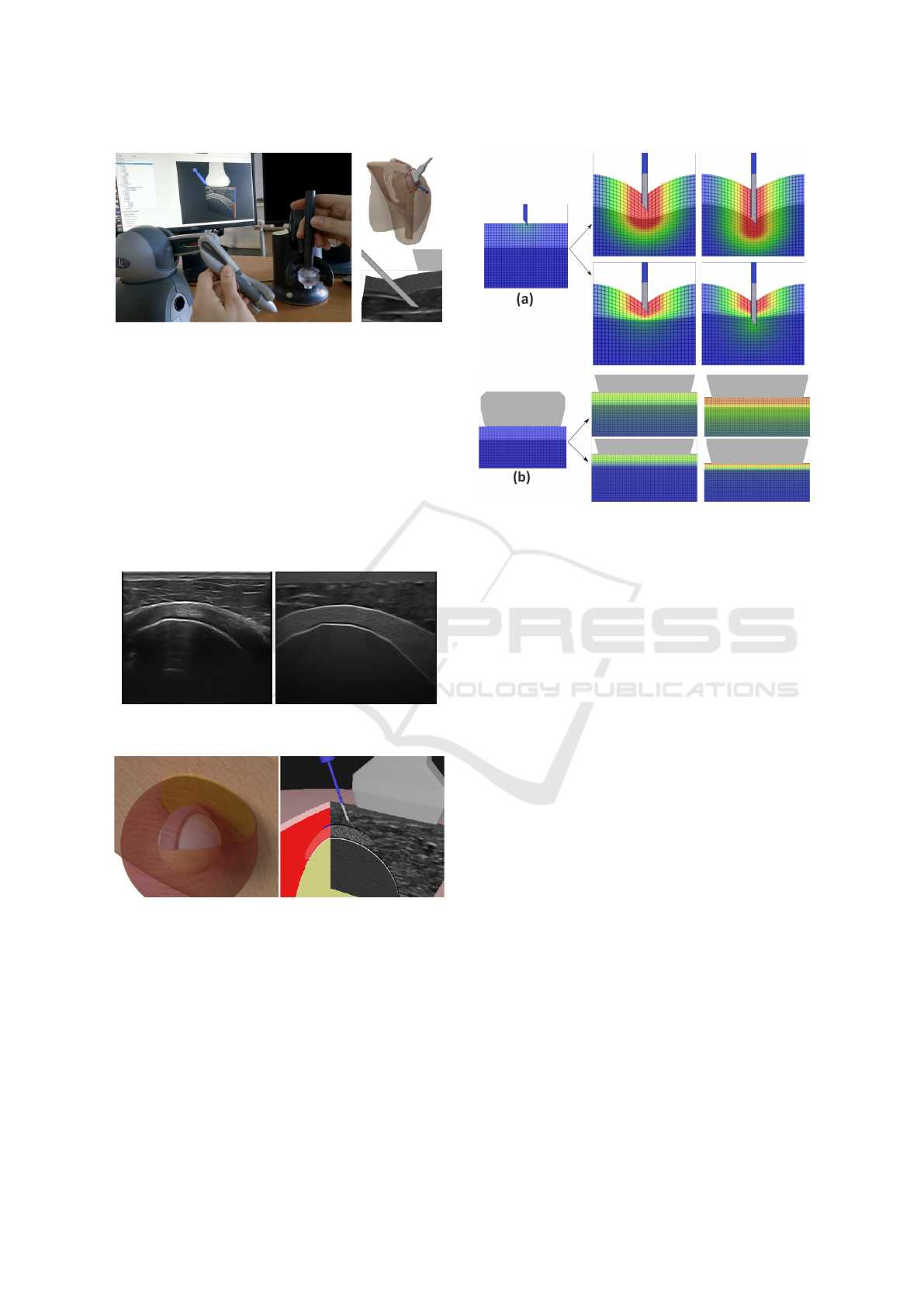
Figure 12: Our simulator which couples a graphical render-
ing with two haptic devices simulating probe and needle.
(up) 3D models (shoulder-probe-needle); (down) zoom on
tissue deformation with ultrasound view.
tissue deformation, similar to the one provided by the
probe used by rheumatologists during the gesture.
US rendering. Fig. 13 presents the reference image
used to create our 3D scene and the US image gen-
erated by our method for the clipping zone of the 3D
scene defined according to the probe position. The
adaptability of our model is presented on a pseudo-
anatomical scene on Fig. 14, coupled with its peda-
gogical US view.
Figure 13: (left) US reference image. (right) The ultrasound
image generated by our process (without deformation).
Figure 14: A scene model seen from behind (left) and the
corresponding pedagogical US view (right).
Fig. 15 shows some results obtained for the dis-
placement of the soft tissues, due to the needle or the
probe, considering a single or two values of E for the
tissues (E = 0.5 and 5N/mm for top and bottom lay-
ers). Fig. 16 presents our final US rendering. On this
figure, we can see the tissue deformation due to the
forces involved by haptic devices (probe or needle):
they are used to alter the texture, allowing a realistic
real-time display of the tissue deformation on the US
image.
Figure 15: Deformation due to (a) the needle and (b) the
probe considering a single (top row) or two values of E (bot-
tom row) for tissues.
Performance. Several tests were performed on a
simple scene, involving a sphere with an increasing
amount of triangles. The sphere acted as a fibrous ob-
ject under deformation. The recorded times (Fig. 17)
are the mean of the first 120 simulation frames. The
results are presented for all render steps.
Even for 7, 864,320 triangles, our rendering runs
in about 0.002 s with all the effects, which is more
than enough for real-time simulation (≈0.06 s). To
compare those results with other existing approaches
on US image generation with mesh deformation, we
ran the tests again and filled the GPU buffer at each
frame (Fig. 18), which takes up to to 99% of frame
rendering time.
We avoid this time consuming step, which would
be mandatory in case of an update of the vertex po-
sitions, as in classical methods. This comparison is
the closest we were able to imagine while avoiding
a tedious implementation of a physically-based soft
tissue deformation system.
The haptic thread itself always runs at around
500 Hz. While lower than the usual frequency of
1,000 Hz, none of the 2 haptic devices has shown par-
asitic vibrations.
8 DISCUSSION
The pipeline presented here allows us to create an US
image from any biological tissue model and from any
GRAPP 2020 - 15th International Conference on Computer Graphics Theory and Applications
244
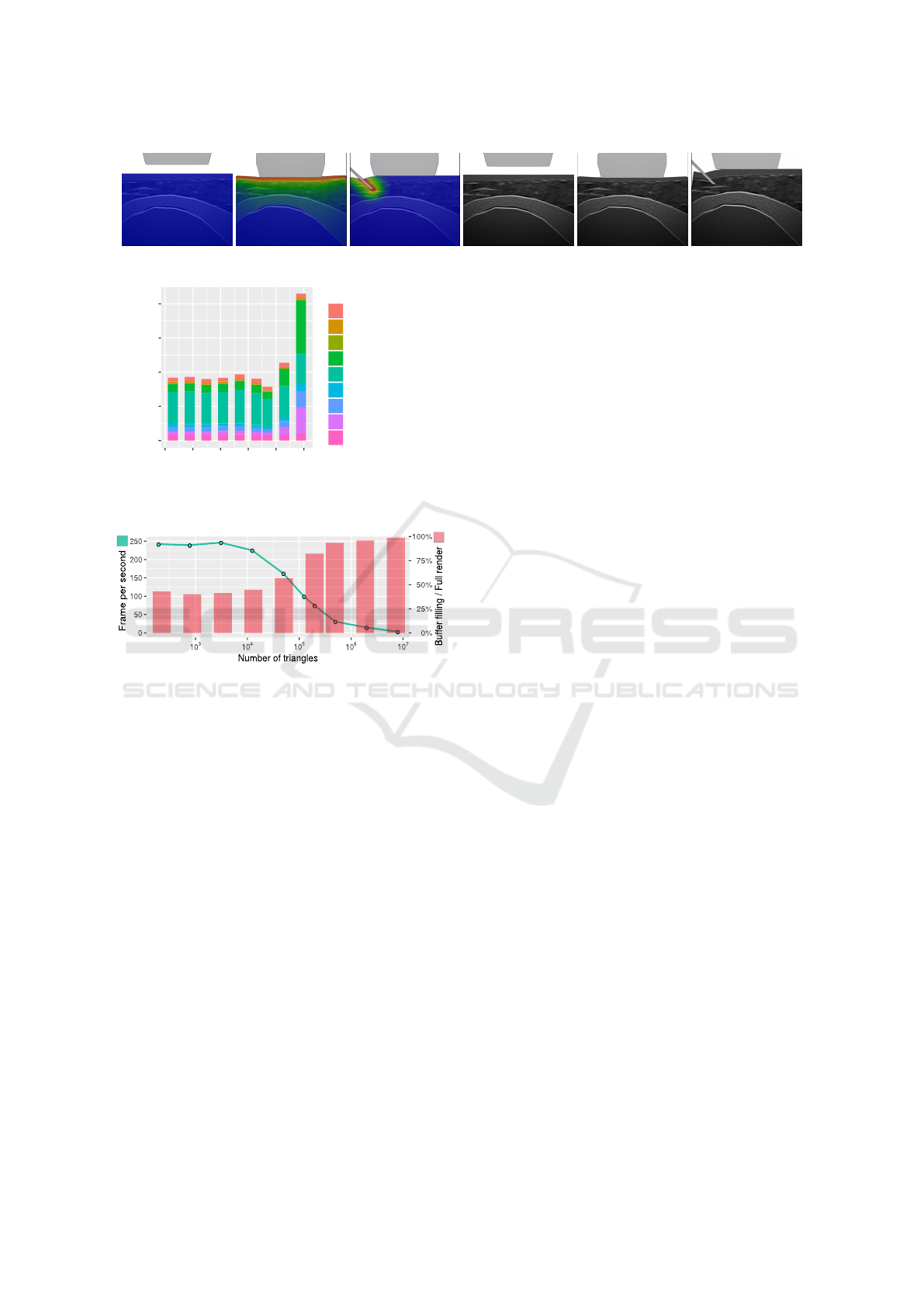
Figure 16: Final US images showing the probe or the needle tissue deformation (w/ or w/o the superposed heatmap).
0.0000
0.0005
0.0010
0.0015
0.0020
10
2
10
3
10
4
10
5
10
6
10
7
Number of triangles
Time (s)
Legend
Add blur
Add deformation
Draw probe and needle
Draw sliced scene
Fill deformation texture
Fill fiber texture
Fill mask texture
Fill reflection map
Fill shadow map
Figure 17: Cumulated time (in seconds) of all the render
steps versus the numbers of triangles (log scale).
Figure 18: Loss in performances using the classical ap-
proach. Loss of FPS (green) and percentage of time to refill
the buffer relative to frame rendering time (red) vs the num-
ber of triangles (in log scale).
probe location and orientation. We avoid the con-
struction of a specific database that might be very de-
pendent on a considered joint or on the location of in-
flammatory tissues. The rendering goes through sev-
eral steps, including shadow, reflection, noise, attenu-
ation and it includes the rendering of fiber orientation,
which to our knowledge has never been presented be-
fore in a real-time simulation. Instead of modeling
the fibrous tissue, we used a texture-based oriented
blur. In related work, we have seen the benefits of the
generative approach to create the ultrasound image,
thanks to its flexibility, even if they still lack some re-
alism when done in real-time environment. To over-
come this, we managed to add the fibrous structure to
better identify the biological tissue.
Some inner structure of non-fibrous tissue, such as
the subcutaneous fat, still lacks details. Voronoi noise
is a possible solution to add realism. Moreover, strong
echoes in some probe orientations produce repetitive
light pattern that are not yet generated in our model
(see Fig. 13).
Concerning the evaluation and comparison of our
images with previous work, it is proved to be diffi-
cult due to the different choices of body region and
the subjectiveness on the quality. Therefore, the de-
tails, ultrasound effects and overall evaluation of our
images is in course with subject-matter experts. We
present here the technical novelties in ultrasound ren-
dering, fiber orientation and real-time image deforma-
tions.
Few real-time needle insertion simulation with
haptic were seen in related works and all on reduced
models. The use of displacement function directly
on the image allows us to work with complex mod-
els without increasing computational time. However,
the displacement functions accuracy depends of a de-
formation model. For example, the current model is
not appropriate for very low of fast velocities, and
lack realism in the relaxation phase. This trade-off
is believed to be the price to pay to cope with perfor-
mances required in real-time environment.
9 CONCLUSION AND
PERSPECTIVE
In this paper, we presented a new way to create an
ultrasound rendering suitable for a needle insertion
training simulator. Our strategy enables to show, in
the ultrasound view, the deformation induced by the
use of two haptic devices which correspond to the
probe and the needle usually used by rheumatologists.
Our proposition brings some breakthroughs.
Firstly, it avoids the use of a 3D volume texture
database. This permits to easily consider several
joints (knee, shoulder), various patient morphology,
various pathologies with inflamed tissues, etc. Sec-
ondly, it permits to display the tissue fibers and their
orientation in the US view. This point visually im-
proves the existing solutions in ultrasound rendering.
Thirdly, our approach enables to show the tissue de-
formations due to the needle insertion. To that end,
our solution deals with the use of textures and dis-
placement models to take advantage of the GPU for
a complete real-time solution. The haptic puncture
forces were calculated using the constrained points
found by continous detections and allow a realistic
A Real-time Ultrasound Rendering with Model-based Tissue Deformation for Needle Insertion
245

deformation inside the US view, leading to improve
the learner immersion sense.
Next step will aim to further improve the visual
rendering of the US image by adding others arti-
facts, and add more complex and precise displace-
ment force, based on physically-based simulations.
ACKNOWLEDGMENTS
This work was supported by French state funds
managed by the ANR within the IDEFI-SAMSEI
(Strat
´
egies d’Apprentissage des M
´
etiers de Sant
´
e en
Environnement Immersif) project. We thank rheuma-
tologist Dr.Coury-Lucas for her valuable feedback,
and E. Galin and J-C. Iehl for their help.
REFERENCES
Abolhassani, N., Patel, R., and Moallem, M. (2007). Needle
insertion into soft tissue: A survey. Medical engineer-
ing & physics, 29(4):413–431.
Bamber, J. and Dickinson, R. (1980). Ultrasonic B-scanning:
a computer simulation. Physics in Medicine & Biology,
25(3):463.
Burger, B., Bettinghausen, S., Radle, M., and Hesser, J.
(2013). Real-time gpu-based ultrasound simulation us-
ing deformable mesh models. IEEE transactions on
medical imaging, 32(3):609–618.
Crouch, J. R., Schneider, C. M., Wainer, J., and Okamura,
A. M. (2005). A velocity-dependent model for needle
insertion in soft tissue. In International Conference on
Medical Image Computing and Computer-Assisted In-
tervention, pages 624–632. Springer.
DiMaio, S. P. and Salcudean, S. E. (2003). Needle inser-
tion modeling and simulation. IEEE Transactions on
robotics and automation, 19(5):864–875.
Duriez, C., Gu
´
ebert, C., Marchal, M., Cotin, S., and Grisoni,
L. (2009). Interactive simulation of flexible nee-
dle insertions based on constraint models. In In-
ternational Conference on Medical Image Computing
and Computer-Assisted Intervention, pages 291–299.
Springer.
Flack, B., Makhinya, M., and Goksel, O. (2016). Model-
based compensation of tissue deformation during data
acquisition for interpolative ultrasound simulation. In
Biomedical Imaging (ISBI), 2016 IEEE 13th Interna-
tional Symposium on, pages 502–505. IEEE.
Gao, D., Lei, Y., and Yao, B. (2013). Analysis of dynamic tis-
sue deformation during needle insertion into soft tissue.
IFAC Proceedings Volumes, 46(5):684–691.
Goksel, O. and Salcudean, S. E. (2009). B-mode ultrasound
image simulation in deformable 3-D medium. IEEE
transactions on medical imaging, 28(11):1657–1669.
Harrison, P. (2001). A non-hierarchical procedure for re-
synthesis of complex textures. WSCG ’2001: Confer-
ence proceedings: University of West Bohemia, Plzen,
Czech Republic, pages 190–197.
Heer, I., Middendorf, K., M
¨
uller-Egloff, S., Dugas, M., and
Strauss, A. (2004). Ultrasound training: the virtual
patient. Ultrasound in Obstetrics and Gynecology,
24(4):440–444.
Jensen, J. A. (1991). A model for the propagation and scat-
tering of ultrasound in tissue. The Journal of the Acous-
tical Society of America, 89(1):182–190.
Law, Y. C., Ullrich, S., Knott, T., Kuhlen, T., and Weg, S.
(2011). Ultrasound image simulation with gpu-based
ray tracing. Virtuelle und Erweiterte Realit
¨
at, 8:183–
194.
Magee, D. and Kessel, D. (2005). A computer based simula-
tor for ultrasound guided needle insertion procedures.
IEE International Conference on Visual Information
Engineering (VIE 2005), pages 301–308.
Magee, D., Zhu, Y., Ratnalingam, R., Gardner, P., and Kessel,
D. (2007). An augmented reality simulator for ultra-
sound guided needle placement training. Medical & bi-
ological engineering & computing, 45(10):957–967.
Marion, A. and Vray, D. (2009). Toward a real-time simula-
tion of ultrasound image sequences based on a 3-d set
of moving scatterers. IEEE transactions on ultrason-
ics, ferroelectrics, and frequency control, 56(10):2167–
2179.
Mattausch, O. and Goksel, O. (2016). Monte-carlo ray-
tracing for realistic interactive ultrasound simulation. In
Proceedings of the Eurographics Workshop on Visual
Computing for Biology and Medicine, pages 173–181.
Eurographics Association.
McReynolds, T. and Blythe, D. (2005). Advanced graphics
programming using OpenGL. Elsevier.
Ni, D., Chan, W. Y., Qin, J., Chui, Y.-P., Qu, I., Ho, S. S.,
and Heng, P.-A. (2011). A virtual reality simulator
for ultrasound-guided biopsy training. IEEE Computer
Graphics and Applications, 31(2):36–48.
Okamura, A. M., Simone, C., and O’leary, M. D. (2004).
Force modeling for needle insertion into soft tis-
sue. IEEE transactions on biomedical engineering,
51(10):1707–1716.
Panozzo, D., Puppo, E., and Rocca, L. (2010). Effi-
cient multi-scale curvature and crease estimation. Pro-
ceedings of Computer Graphics, Computer Vision and
Mathematics (Brno, Czech Rapubic, 1(6).
Takabi, B. and Tai, B. L. (2017). A review of cutting me-
chanics and modeling techniques for biological materi-
als. Medical engineering & physics, 45:1–14.
van Gerwen, D. J., Dankelman, J., and van den Dobbelsteen,
J. J. (2012). Needle–tissue interaction forces–a survey
of experimental data. Medical engineering & physics,
34(6):665–680.
Vidal, F. P., John, N. W., Healey, A. E., and Gould, D. A.
(2008). Simulation of ultrasound guided needle punc-
ture using patient specific data with 3D textures and vol-
ume haptics. Computer Animation and Virtual Worlds,
19(2):111–127.
Yang, C., Xie, Y., Liu, S., and Sun, D. (2018). Force
modeling, identification, and feedback control of robot-
assisted needle insertion: a survey of the literature. Sen-
sors, 18(2):561.
Zilles, C. B. and Salisbury, J. K. (1995). A constraint-based
god-object method for haptic display. In Intelligent
Robots and Systems 95.’Human Robot Interaction and
Cooperative Robots’, Proceedings. 1995 IEEE/RSJ In-
ternational Conference on, volume 3, pages 146–151.
IEEE.
GRAPP 2020 - 15th International Conference on Computer Graphics Theory and Applications
246
