
Virtual Planning and Testing of AUV Paths for Underwater
Photogrammetry
Amy Lewis
1
, Kolton Yager
1
, Mitchell Keller
1
, Bonita Galvan
1
, Russell C. Bingham
2
,
Samantha Ting
2
, Jane Wu
2
, Timmy Gambin
3
, Christopher Clark
2
and Zo
¨
e J. Wood
1
1
Computer Science Department, Cal Poly, San Luis Obispo, U.S.A.
2
Engineering Department, Harvey Mudd College, Claremont, U.S.A.
3
Department of Archaeology, University of Malta, Malta
Keywords:
Photogrammetry, AUV Path Planning, Viewpoint Planning, 3D Reconstruction.
Abstract:
We introduce a system for automatically generating paths for autonomous underwater vehicles which optimize
views of a site of interest. These paths can then be used to survey and map underwater sites of interest using
photogrammetry. Paths are generated in a virtual world by a single-query probabilistic roadmap algorithm that
quickly covers the configuration space and generates small maps with good coverage. The objective function
used to compute the paths measures an approximate view coverage by casting rays from the virtual view to
test for intersections with the region of interest, with added weight for views with high information gain.
The motion planning algorithm was implemented in a virtual world that includes the ability to test paths and
acquire views of the virtual scene for evaluation prior to real world deployment. To measure the effectiveness
of our paths versus the commonly used pre-packaged lawnmower paths, photogrammetry reconstructions were
compared using CloudCompare. The 3D reconstructions created from the views along the paths generated by
our algorithm were more detailed and showed better coverage, creating point clouds with a mean distance
between points ranging from 1.5 to 2.3 times better than that of the lawnmower pattern.
1 INTRODUCTION
Searching for archaeological sites underwater in-
volves time consuming field work and expensive
equipment. A common approach is to select a large
area to explore then conduct a survey, for example us-
ing a towfish for sonar mapping from a boat. Sonar
data is then analyzed by experts (or intelligent sys-
tems (Rutledge et al., 2018)) which rank potential
sites of interest. The sites are revisited, for example,
by an accomplished human dive team or remotely op-
erated vehicles (ROVs).
A potentially safer and less expensive solution is
the use of Autonomous Underwater Vehicles (AUVs)
for both survey and site mapping. The work presented
here focuses on the problem of developing good paths
for the AUV to map a site for photogrammetry recon-
structions using an on-board goPro camera. The goal
is to acquire good camera views of the site of inter-
est for reconstructions. Building from an initial sonar
scan which is used to determine the extents of the site
of interest, our algorithm creates paths for the AUV
to map the site. A set of the video image frames is
then used for photogrammetry to create a 3D recon-
struction which can be used for educational and site
monitoring purposes.
In general, determining the path for an au-
tonomous vehicle has applications to many fields.
Our specific path planning algorithm prioritizes col-
lecting images of all sides of a region of interest with
good coverage by using a probabilistic roadmap algo-
rithm. The path planning algorithm takes into account
the geometry of the site of interest and general physi-
cal constraints of the AUVs movement. The objective
function weights potential positions based on the view
of the on-board camera of the region of interest.
We present our path planning algorithm and a vir-
tual world testbed, where various paths can be tested
and compared. A virtual camera collects images
along the automatically generated paths and those im-
ages are then used to create 3D models and point
clouds using photogrammetry. Most AUVs include
easy to use motion planning for surveys in the form of
‘lawnmower’ patterns. To measure the effectiveness
of our paths versus the commonly used pre-packaged
lawnmower paths, the 3D models and point clouds
Lewis, A., Yager, K., Keller, M., Galvan, B., Bingham, R., Ting, S., Wu, J., Gambin, T., Clark, C. and Wood, Z.
Virtual Planning and Testing of AUV Paths for Underwater Photogrammetry.
DOI: 10.5220/0008943300930101
In Proceedings of the 15th International Joint Conference on Computer Vision, Imaging and Computer Graphics Theory and Applications (VISIGRAPP 2020) - Volume 1: GRAPP, pages
93-101
ISBN: 978-989-758-402-2; ISSN: 2184-4321
Copyright
c
2022 by SCITEPRESS – Science and Technology Publications, Lda. All rights reserved
93
created from the different paths were compared. The
paths generated by our algorithm captured images re-
sulting in 3D reconstruction which were more de-
tailed and showed better coverage of the site of inter-
est than those from the lawnmower pattern. Our work
is primarily focused on underwater shipwrecks, thus,
our testbed includes a simple boat model. A com-
parison of the side profiles of an original virtual boat
model, the 3D model created from images captured
along the lawnmower pattern, and the 3D model gen-
erated from images along the path computed by our
algorithm is shown in Figure 6.
1.1 Field Work and Motivation
This path planning work arose from extensive field
work in the coastal waters of Malta (Wu et al., 2019;
Rutledge et al., 2018; von Fock et al., 2017a). Ini-
tial work using a 2D bounding box, seen in Figure 1
on real sonar data, showed promising results for re-
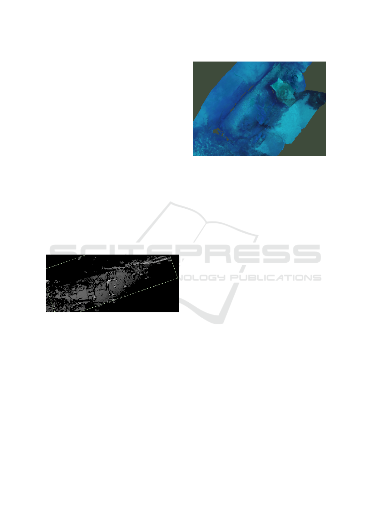
constructions. See Figure 2 for a reconstruction of a
World War 2 shipwreck created from the initial 2D
bounding box paths. Due to time, weather and cost
limitations to deployments, this virtual testbed was
developed to test and evaluate further motion plan-
ning.
Figure 1: An example of the 2D bounding box of a region
of interest produced from field deployments (see (Wu et al.,
2019; Rutledge et al., 2018; von Fock et al., 2017a) for more
information).
2 RELATED WORKS
Motion planning for robots is well studied (Dudek
and Jenkin, 2010; Demofox, 2015; Alcazar et al.,
2011) with this work building on many of the prior
algorithms. Garau, Alvarez, and Oliver introduce
a heuristic cost function that estimates the time the
AUV would need to travel from one grid point to the
next (Garau et al., 2006). Rao and Williams present
a rapidly-exploring random tree (RRT) algorithm to
plan collision-free paths for an underwater glider in
3D space (Rao and Williams, 2009). Tan, Sutton,
and Chudley also propose a RRT algorithm to plan
Figure 2: Example model reconstruction from images ac-
quired along a 2D bounding box motion planned deploy-
ment.
collision-free paths in three-dimensions while also ac-
counting for vehicle dynamics (Tan et al., 2017).
There is likewise a rich body of work address-
ing the field of photogrammetry (Yamafune et al.,
2016), and AUV path planning (Rantanen, 2014; Li
and Shie, 2002; Dale and Amato, 2001; Poppinga
et al., 2011; Candeloro et al., 2015; Wu et al., 2019).
Viswanathan et al. implemented a motion planner
with an RRT with a goal similar to ours (Viswanathan
et al., 2017). Our work was also influenced by a
probabilistic roadmap planning algorithm to gener-
ate virtual camera paths for fly-throughs of a digital
scene (Davis, 2017). And related later work (Clark
et al., 2017), which aimed to create good cinemato-
graphic and geometric views. However, in this prior
work, rotation is only free around one axis instead of
two as in our algorithm.
Yamafune et al. share the same goal in their work
as our own - to survey shipwrecks for the purpose of
reconstruction (Yamafune et al., 2016), however, they
use a team of professional human divers to capture
their video data. It is worth noting that they recom-
mend that divers capture many circular views for opti-
mal reconstructions and the proposed paths look very
much like a lawnmower pattern.
Dunn et al. present a path planner for autonomous
vehicles with a goal of creating detailed 3D recon-
structions (Dunn et al., 2009). Computer vision is
used to obtain the geometric structure of the scene be-
ing reconstructed and a path with ‘the next best view’
is determined by their novel cost function that “quan-
tifies the expected contribution of future viewing con-
figurations”. In addition, related work includes recent
work for drone trajectory optimization (Hepp et al.,
2018) for an aerial path to capture data for photogram-
metry.
Within the context of related work, our algorithm
GRAPP 2020 - 15th International Conference on Computer Graphics Theory and Applications
94

is novel in its algorithmic computation of view cov-
erage to weight roadmap nodes, tuned for the task of
capturing images of all sides of a site of interest for
an underwater vehicle, thereby improving coverage.
3 ALGORITHM
To generate AUV paths, this system uses a robotics
motion planning algorithm - single-query probabilis-
tic roadmaps (PRM). This algorithm quickly cov-
ers the configuration space and generates small maps
with good coverage. In order to create a viable 3D
reconstruction of a site of interest, it is important for
the camera to capture good views of all regions. Our
path planning algorithm seeks to ensure that for the
discrete nodes along the path that the AUV visits, the
camera is viewing significant portions of the site of
interest as well as ensuring all regions of the site have
been viewed. Geometric principles, primarily an ap-
proximation of how much of the main site of inter-
est is in view of the camera, are used to set node
weights and select nodes to include in the path for
the AUV. Specifically, the objective function used in
our algorithm measures an approximate view cover-
age by casting rays from the camera and intersecting
them with the region of interest.
For our path planning, the algorithm solves for
the motion within a virtual representation of a gen-
eral volume of space (in our case, sea) surrounding
the region of interest. This region of interest is identi-
fied from low resolution side scan sonar data obtained
from a high altitude scan by the AUV (Rutledge et al.,
2018). A bounding box is computed based on an
automatically detected region of interest (Wu et al.,
2019), defining both the site to be mapped as well as
a no ‘fly’ zone (to prevent collisions). Assuming a
mapping between real-world GPS and sonar coordi-
nates and the virtual world, ultimately, the configura-
tion space is the x,y,z position and pitch-yaw of the
camera (relative to the AUV) within the extents of the
virtual world. Constraints are used to model the pos-
sible AUV turning radius between nodes and the fact
that the camera is fixed to the AUV while traveling
along a path. From the bounding box, a starting po-
sition for the AUV is chosen and a roadmap is built,
expanding nodes branching from the prior node until
a path which visits all visible sides of the bounding
box has been found.
Our algorithm uses a discrete representation of the
camera’s frustum and computes an intersection quan-
tity for possible views (derived from potential vehicle
positions). Using this metric, a path can be planned
that maximizes camera coverage of all of the sides
of the site of interest. Figure 3 illustrates an inter-
section between the camera’s view frustum and the
site of interest’s bounding box. After a path has been
found, discrete images from the perspective of the vir-
tual camera travelling the planned path can be used to
create a reconstruction of the site. The reconstruc-
tion can then be compared to the original 3D model
or other reconstructions to measure the overall path
viability.
We solve for a vehicle path considering nodes in
the configuration space. Physical considerations such
as the camera being oriented 90 degrees orthogonal
to the vehicle, allow the camera frame to be derived
from the vehicle velocity. Velocity is what determines
the magnitude and the direction in which the robot
moves towards the next node in the path. Other values
stored in each node for the algorithm include weights
determined by the objective function and parent in-
formation. For each node, we also keep track of a
lightweight representation of the sides of the region of
interest which have, so far, been seen in an unsigned
integer using 5 bits.
The basic algorithm is as follows:
while bboxSideCoverage < desiredCoverage
do
// select node n to expand from
if declustering then
n ← node from voxel with least
nodes;
end
else
if even iteration of loop then
n ← random node in
highWeightNodes;
end
else
do
n ← random node in
roadmap;
while n < weightThreshold;
end
end
randomly generate n’ from n;
calculate edge e from n to n’;
Roadmap.add(n’, e);
bboxSideCoverage ← n’.bBoxcoverage;
n’.weight ← calculateWeight(n’);
if n’.weight > highWeightThreshold then
highWeightNodes.add(n’);
end
end
Virtual Planning and Testing of AUV Paths for Underwater Photogrammetry
95
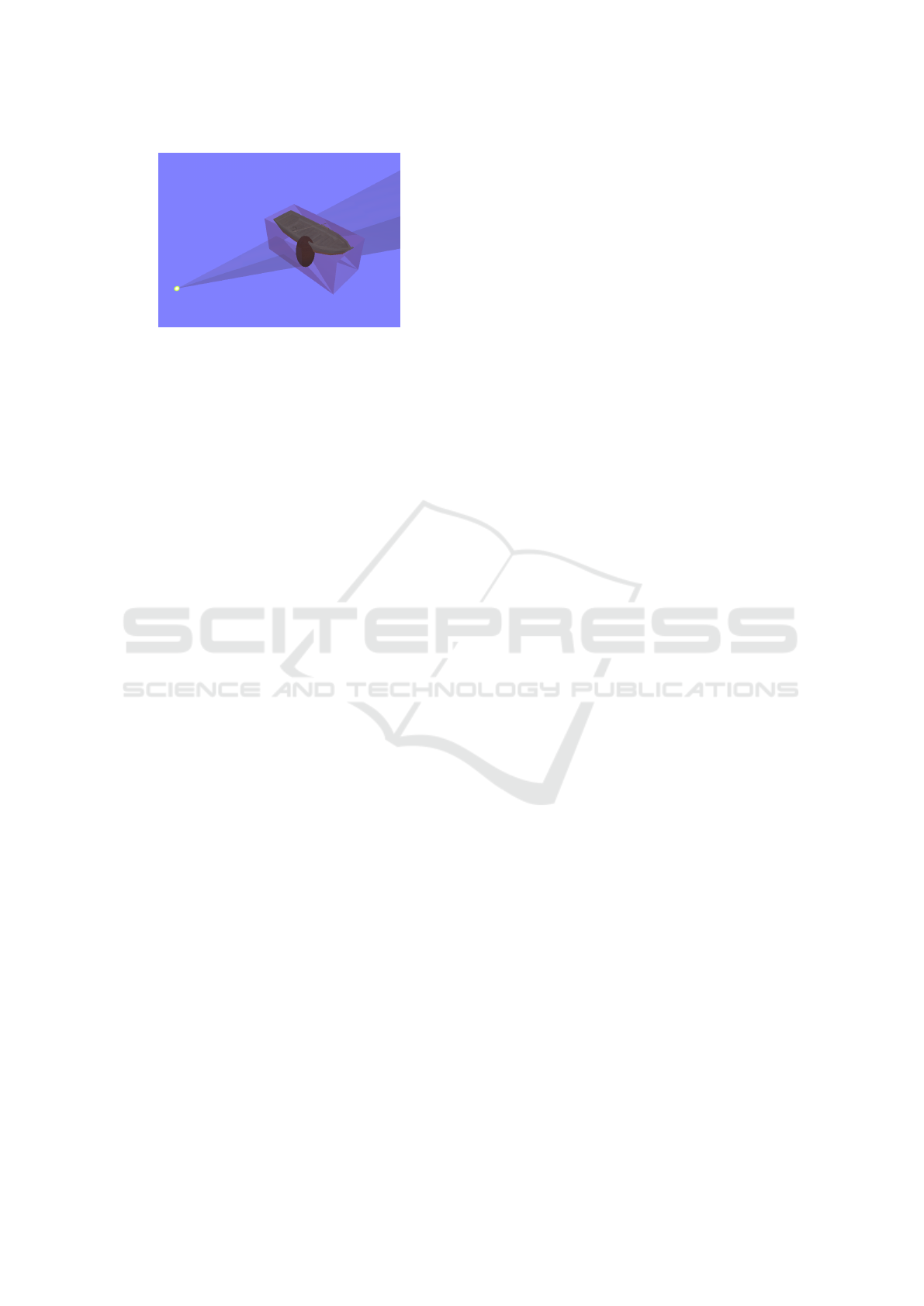
Figure 3: Visualization of the camera view frustum, in this
case intersecting with the bounding boxes representing the
region of interest.
Node Selection. The algorithm starts with the selec-
tion of a root note, which is added to the roadmap and
the algorithm proceeds with the node selection step.
For node selection, we must choose a node n from the
roadmap to expand from.
All nodes in the roadmap are stored in a 3D uni-
form spatial grid. The 3D grid is represented as
C = c
i jk
|i = 1,...,m; j = 1,...,n; k = 1,...o. The three
dimensions of C refer to discretized values of the x, y,
and z coordinates of the virtual world. Each newly
created node is inserted into the spatial data struc-
ture by its x,y,z location. The i, j,k space is twice
the magnitude of the original bounding box acquired
from a high altitude sonar scan, but this scaling is con-
figurable.
For all nodes, n, a weight measuring the node’s
viewpoint is computed. To compute n.weight, three
main criteria are used:
• Viewpoint quality: the view frustum for this node,
(where n includes x,y, z and pitch and yaw) is dis-
cretized as a matrix of 200 rays. These rays are
intersected with the bounding box of the region of
interest. Any ray that intersects with a side of the
bounding box contributes towards the total weight
for the current node,
n.weight =
∑
(RayHits)/totalRays (1)
• Information gain via new side coverage: If a node
offers a view of a side of the bounding box of
the region of interest that has not previously been
seen, the weight of the node is significantly in-
creased, +c. The algorithm is able to distinguish
that a side is newly seen by keeping a record
of viewed sides for each node, n. To reduce
the memory footprint of nodes in the complete
roadmap, each node holds an unsigned int with
five bits used to encode which sides of the region
of interest have been seen (via ray intersections
with sides of the bounding box denoted with a
unique bit). This encoding can be compared to
the prior node to distinguish the viewing of a new
side.
• Viewpoint gain: If the current node has a higher
weight than its parent, an additional contribution,
+delta, is added to promote expansion towards
promising directions.
Node weights are used in the selection step of the al-
gorithm to balance both exploration and targeted se-
lection.
Node selection alternates to optimize various mo-
tion planning goals.
• For declustering, to promote expansion in all di-
rections, the voxel i, j,k that contains the least
number of nodes is selected for expansion every
other expansion
• For pruning, on every other step we alternate be-
tween selecting:
1. a node from the list of “high weight” nodes.
Weights for an initial 440 nodes are placed in a
discrete grid around the region of interest. The
high weight threshold is then initialized to the
average weight plus the standard deviation of
these initial nodes:
highWeightT hresh =
m
∑
i=1
n
i
.weight/m + σ (2)
These nodes have better then average view-
points.
2. a random node with a weight above a signif-
icantly lower minimum threshold value. This
minimum threshold decreases with each iter-
ation to promote node selection even if the
roadmap only contains low quality nodes.
The declustering step prevents the roadmap from
producing too many nodes in a single area that offers
high weight views of the region of interest, encour-
aging exploration and coverage of the configuration
space. By selecting higher weight nodes, the algo-
rithm effectively prunes low quality directions and de-
creases the potential size of the roadmap.
Node Generation. In order to cover the entire
scene, the roadmap must expand to a new node, n
0
.
Once a node to expand from has been selected as de-
scribed above, a new node is generated based off the
prior node. The velocity of the prior node is taken and
a new velocity with a randomly perturbed pitch and
yaw is added to it. A delta value, within a range of
0 and π of the prior node’s pitch is randomly chosen.
The new delta value is then added to phi. The same
process happens for yaw with a delta added to theta.
GRAPP 2020 - 15th International Conference on Computer Graphics Theory and Applications
96
The new, perturbed pitch and yaw are then used to cal-
culate the new velocity. The new velocity is added to
the previous position, creating the position of the new
node, n
0
. If that is, in fact, a valid position and not col-
liding with the region of interest, then the orientation
for the robot at that position is calculated.
Path Completion. Our algorithm terminates when
all sides of the region of interest have been seen. Each
time a node is added to the roadmap, the algorithm
evaluates if all sides of the bounding box around the
region of interest have been seen. After the final side
has been seen, the algorithm runs for a finite amount
of time. The time limit is an experimental choice and
other methods to ensure further coverage of the final
side of the region of interest could be explored. The
final path is generated from the roadmap by follow-
ing parent nodes from the final node to the root node.
The nodes along this path can then be used to replay a
virtual path to gather images for reconstruction in our
virtual testbed. Future work includes mapping these
points from the virtual space back to real world GPS
coordinates which can then be used as way points for
an AUV trajectory around the real site of interest.
Using Paths in the Testbed. As underwater vehi-
cle deployments can be challenging (in terms of cost,
weather, etc.), we sought to design a virtual platform
to plan and test AUV paths and camera views. The
virtual world used in our testbed is an OpenGL appli-
cation which, in its current implementation, includes
simple geometric models. The ground plane repre-
sents the seafloor and is textured with an image of
a sandy seafloor like that of the Mediterranean. To
generate motion between the nodes, the positions is
interpolated using a cubic Hermite interpolation func-
tion creating a spline (Demofox, 2015). An image is
captured every third frame by the virtual camera as it
follows the generated spline. Building off the work of
(von Fock et al., 2017b), we use the frames from the
paths to construct a model of the target of interest.
4 RESULTS
We present a probabilistic roadmap algorithm for the
generation of paths for an AUV to travel in order to
capture multiple views of a region of interest with
good coverage. In addition, we present an applica-
tion to test these paths in a virtual environment which
uses simple geometry but allows for virtual frames to
be written out and then used with a photogrammetry
application for path evaluation.
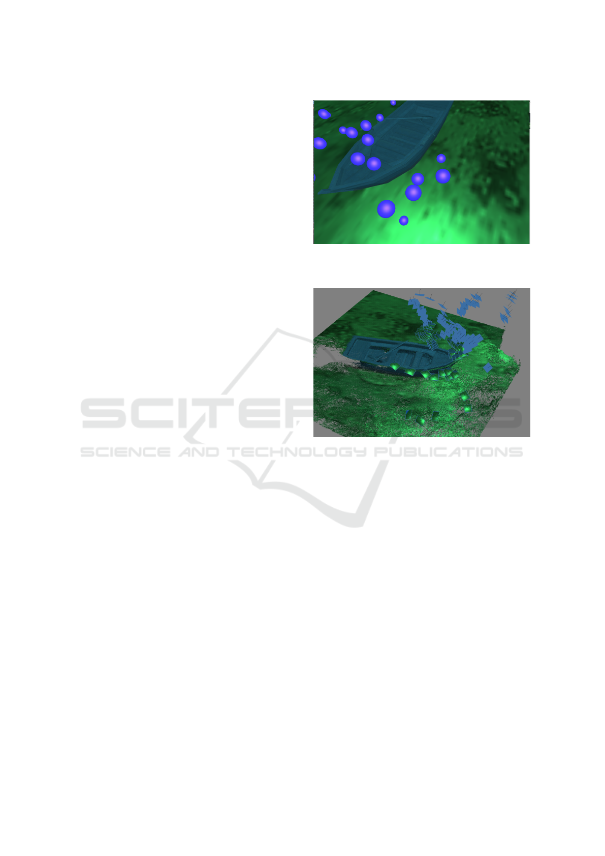
Figure 4: Each node (blue sphere) represents a configura-
tion of the AUV while following the path. A path is made
by moving between these nodes.
Figure 5: Image showing the example images and subse-
quent reconstruction from aligned input images captured
from a virtual path for one side of the model.
To measure the effectiveness of our paths, the
3D models and point clouds created from our algo-
rithm were compared to those generated from running
a standard pre-packaged lawnmower pattern. The
paths generated by our algorithm captured images that
could be used in a 3D reconstruction, that were more
detailed and that showed better coverage of the region
of interest than those from the lawnmower pattern.
Point clouds of each reconstruction are also compared
to determine the level of detail of each.
4.1 Measures
To test the quality of images generated by the various
paths, we used Agisoft Photoscan
R
for photogram-
metry. We selected a set of twelve paths created by
our algorithm to consider for comparisons. In ad-
dition, image frames from three lawnmower pattern
paths were also captured for comparison. While one
set of lawnmower path images led to a good recon-
struction, the other two, including an attempt to run
Virtual Planning and Testing of AUV Paths for Underwater Photogrammetry
97
the pattern created by Yamafune et al. (Yamafune
et al., 2016), failed to produce usable models at all.
For the one lawnmower path that was able to produce
a reconstruction, the 3D model and point clouds are
compared to the original 3D model of the shipwreck
(i.e., the site of interest).
One of the key steps in photogrammetry is image
alignment (see Figure 5) and the number of aligned
images directly corresponds to the amount of data us-
able in the reconstruction. The percentage of aligned
images for the comparison paths are shown in Table 1.
On average, at least 57% of the images from our paths
are aligned. Reconstructions were created for three of
our paths, PRM 1 and PRM 6 and PRM 11. While
PRM 1 has very good image alignment, the the later
two paths are more average and are included to show
that even average paths created by our algorithm can
produce better results than a reconstruction following
the lawnmower pattern.
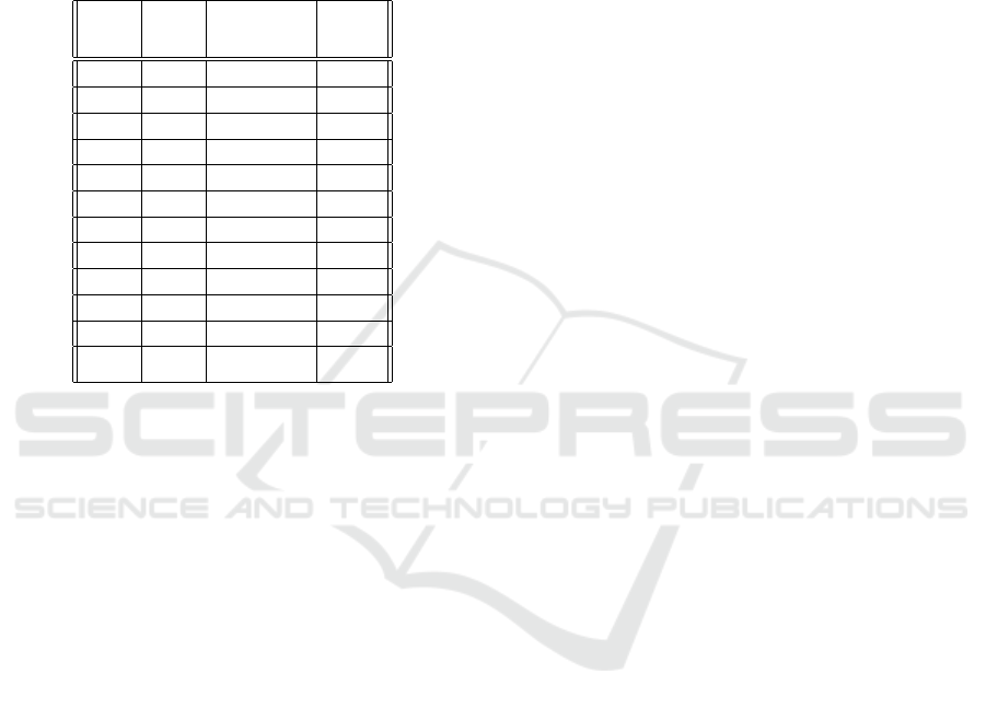
Table 1: Summary of Paths with Good Potential. Includes
the images aligned, the percent of those actually aligned,
and the average weight of each path.
Path Images Percent Average
Aligned Aligned Weight
1 599/608 98.52 0.54
2 121/666 18.17 0.52
3 468/551 84.94 0.58
4 198/614 32.25 0.51
5 296/641 46.18 0.57
6 790/1322 59.76 0.57
7 476/988 48.18 0.56
8 429/743 57.74 0.54
9 544/646 84.21 0.57
10 83/268 30.97 0.56
11 295/573 51.48 0.57
12 478/592 80.74 0.55
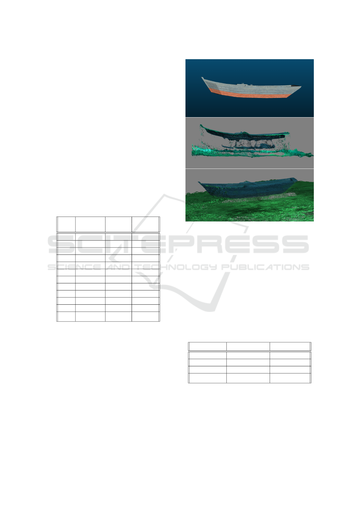
Figure 6 shows the side profiles of the reconstruc-
tions for PRM 6 and the lawnmower pattern along-
side the original 3D model. It is clear that the recon-
struction generated from images from our paths in-
clude much more complete model information, while
the model reconstructed from a lawnmower pattern is
missing the sides of the model. One limitation of the
current work is that given the small scale of our cur-
rent virtual testbed, both our paths and lawnmower
produced good reconstructions of the top of the ship-
wreck as shown in Figure 8 and Figure 7.
Point clouds of all of the reconstructed 3D models
were compared using CloudCompare. In general, the
denser the point cloud, the more detailed the recon-
struction. One measure of the density is the mean dis-
tance between points, with smaller distances between
Figure 6: Comparison of a 3D Model and two point cloud
reconstructions, one from images captured from a standard
‘lawnmower pattern’, and the much more complete recon-
struction from images using a path created with our algo-
rithm.
points indicating greater density. Figure 8 and Figure
9 show point clouds in blue created from our paths,
over the gray point cloud created from the original
model. As shown in the images and reinforced in the
data displayed in Table 2, the point clouds created by
our paths are significantly more dense than the point
clouds created by the lawnmower pattern. The mean
distance of the point clouds produced by our paths
range from being 1.5 to 2.3 times better than that of
the lawnmower pattern.
Table 2: Point Cloud data for PRM and lawnmower paths.
Path Mean Distance Std Deviation
PRM 3 0.15 0.19
PRM 6 0.12 0.39
PRM 11 0.23 0.59
Lawnmower 0.34 0.43
When comparing the paths, it is worth noting that
the total distance of each path does not correlate to
the quality of the reconstruction. Table 3 shows the
distance each path covered in the virtual world. The
lawnmower pattern covers a distance of almost twice
as far as path PRM 11, but PRM 11 is a better recon-
struction overall.
GRAPP 2020 - 15th International Conference on Computer Graphics Theory and Applications
98
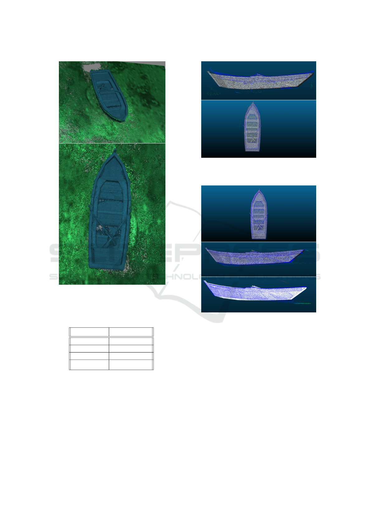
Figure 7: Additional views of the 3D Models created by
images captured along paths using our algorithm (PRM 11
and PRM 6).
Table 3: Total distance by the selected paths in virtual world
units.
Path Total Distance
PRM 3 1678.94
PRM 6 2270.19
PRM 11 664.24
Lawnmower 1128.49
Performance. All work was executed for testing on
a 2019 MSI GS63 Stealth with an Intel 8th Genera-
tion Core i7-8750H processor. The computer also has
a dedicated graphics card - NVIDIA Geforce GTX
1060. The code was written in C++14 along with the
Open Graphics Library (OpenGL) version 4.6. The
OpenGL Mathematics library, GLM, version 0.9.8.5
and GLFW3 version 3.2 were also used.
The objective function has a significant effect on
performance. Initially, the algorithm was allowed
Figure 8: Point cloud produced from reconstruction using
images from following a lawnmower pattern path. Note the
mismatch on the sideview.
Figure 9: Top and side view of the point clouds produced
from reconstruction using images from our paths (3 and 11
specifically).
to expand by choosing a node completely randomly
from the roadmap. On multiple occasions, the algo-
rithm was left to run overnight without generating a
complete path because it either never saw all sides of
the region of interest or the computer ran out of mem-
ory. When the high weight threshold was added to
the node selection process, path generation went from
taking hours to minutes.
An important optimization to performance for this
project was the use of a hash map to represent the
spatial data structure, allowing the algorithm to look
up the voxel with the least amount of nodes rapidly.
As shown in Table 4, all of the generated paths took
between 10 and 27 seconds of computation. Table
4 shows a summary of the generated paths including
Virtual Planning and Testing of AUV Paths for Underwater Photogrammetry
99
the length of each path, the number of nodes in each
respective roadmap, and the time it took to generate
them. The larger the roadmap, the more time the algo-
rithm took to create a path, however, even the largest
roadmap with 538 nodes took only 27 seconds to gen-
erate a path.
Table 4: Summary of generated paths. Includes the number
of nodes of each path, the number of nodes in each roadmap,
and the time to generate each path in seconds.
Path Path Roadmap Time
Size Size (s)
1 20 36 10
2 62 99 15
3 160 261 23
4 87 193 17
5 33 48 11
6 207 407 26
7 76 178 16
8 118 189 20
9 92 137 20
10 155 234 22
11 61 100 14
12 189 538 27
5 CONCLUSIONS
We have presented a virtual path planning and testing
system to help plan paths for underwater vehicles to
map underwater sites of interest. The 3D models cre-
ated by the paths computed using our algorithm are
more detailed and show better coverage of all sides
than those created by the lawnmower pattern. The
images gathered along our paths also created signifi-
cantly denser point clouds than the lawnmower paths,
with a mean distance between points that ranges from
1.5 to 2.3 times better than that of the lawnmower pat-
tern.
This project represents the culmination of a large
amount of experience in field work focused on map-
ping underwater sites of interest (Wu et al., 2019; Rut-
ledge et al., 2018; von Fock et al., 2017a), however,
there are many areas for future work including: test-
ing the paths in a real world setting and expanding the
algorithm to account for multiple bounding boxes.
For real world AUV paths, while underwater the
AUV’s location accumulates error as time goes on (an
acoustic underwater positioning system would give
measurements with bounded error, but these systems
are not always in place). Therefore, in order to con-
vert the automatically generated paths to ones that
could be accurately used with the AUV, additional
way-points (nodes) will be added. Pairs of nodes with
similar velocities would be selected and correspond-
ing surface way-points would be appropriately spaced
to reach the correct depth for each node before and
after the node pairs are added to the final path. This
process would be repeated until all nodes are paired
and associated with surface way-points. The AUV
would then travel to each way-point until the path is
complete. We hope to complete field testing of our
system in the upcoming year. Additional future work
includes deeper exploration and comparisons to other
motion planning algorithms.
ACKNOWLEDGEMENTS
We would like to acknowledge the entire 2017 and
2018 ICEX teams. This material is based upon work
supported by the National Science Foundation under
Grant No. 1460153.
REFERENCES
Alcazar, V., M. Veloso, M., and Borrajo, D. (2011). Adapt-
ing a rapidly-exploring random tree for automated
planning.
Candeloro, M., Mosciaro, F., Srensen, A. J., Ippoliti, G.,
and Ludvigsen, M. (2015). Sensor-based autonomous
path-planner for sea-bottom exploration and mosaick-
ing. In IFAC Conference on Manoeuvring and Control
of Marine Craft, pages 31–36.
Clark, C., Lewis, A., Freed, S., Rutledge, J., and Wood,
Z. (2017). Auv and graphics research motivated by
marine archaeology: From development to discov-
ery. In International Conference on Aviation Archae-
ology and Heritage (ICAAH), Valetta, Malta. Heritage
Malta.
Dale, L. K. and Amato, N. M. (2001). Probabilistic
roadmaps-putting it all together. In Proceedings 2001
ICRA. IEEE International Conference on Robotics
and Automation (Cat. No.01CH37164), volume 2,
pages 1940–1947 vol.2.
Davis, K. (2017). Probabilitic roadmaps for virtual cam-
era pathing with cinematographic principles. Mas-
ter’s thesis, California Polytechnic State University -
San Luis Obispo, 1 Grand Ave. San Luis Obispo, CA
93405.
Demofox (2015). Cubic hermite interpola-
tion. https://blog.demofox.org/2015/08/08/
cubic-hermite-interpolation/.
Dudek, G. and Jenkin, M. (2010). Computational Princi-
ples of Mobile Robotics. Cambridge.
Dunn, E., Berg, J. v. d., and Frahm, J. (2009). Developing
visual sensing strategies through next best view plan-
ning. In 2009 IEEE/RSJ International Conference on
Intelligent Robots and Systems, pages 4001–4008.
GRAPP 2020 - 15th International Conference on Computer Graphics Theory and Applications
100

Garau, B., Alvarez, A., and Oliver, G. (2006). Path planning
of autonomous underwater vehicles in current fields
with complex spatial variability: an a* approach. In
Proceedings of the 2005 IEEE International Confer-
ence on Robotics and Automation, pages 194–198.
IEEE.
Hepp, B., Nießner, M., and Hilliges, O. (2018). Plan3d:
Viewpoint and trajectory optimization for aerial multi-
view stereo reconstruction. ACM Trans. Graph.,
38(1):4:1–4:17.
Li, T.-Y. and Shie, Y.-C. (2002). An incremental learn-
ing approach to motion planning with roadmap
management. In Proceedings 2002 IEEE Interna-
tional Conference on Robotics and Automation (Cat.
No.02CH37292), volume 4, pages 3411–3416 vol.4.
Poppinga, J., Birk, A., Pathak, K., and Vaskevicius, N.
(2011). Fast 6-dof path planning for autonomous un-
derwater vehicles (auv) based on 3d plane mapping.
In IEEE International Symposium on Safety, Security,
and Rescue Robotics (SSRR), pages 1–6. IEEE Press,
IEEE Press.
Rantanen, M. (2014). Improving Probabilistic Roadmap
Methods for Fast Motion Planning. PhD thesis,
School of Information Sciences, University of Tam-
pere.
Rao, D. and Williams, S. B. (2009). Large-scale path plan-
ning for underwater gliders in ocean currents. In
Australasian Conference on Robotics and Automation
(ACRA).
Rutledge, J., Yuan, W., Wu, J., Lewis, A., Freed, S., Wood,
Z., and Clark, C. (2018). Intelligent shipwreck search
using autonomous underwater vehicles. IEEE In-
ternational Conference on Robotics and Automation
(ICRA), pages 1–8.
Tan, C. S., Sutton, R., and Chudley, J. (2017). An in-
cremental stochastic motion planning technique for
autonomous underwater vehicles. volume 37, pages
483–488.
Viswanathan, V., Lobo, Z., Lupanow, J., von Frock, S.,
Gambin, T., Wood, Z., and Clark, C. (2017). Auv
motion-planning for photogrammetric reconstruction
of marine archaeological sites. IEEE International
Conference on Robotics and Automation (ICRA),
pages 5096–5103.
von Fock, S., Davis, K., Bilich, S., Viswanathan, V., Lobo,
Z., Lupanow, J., Gambin, T., Wood, Z., and Clark, C.
(2017a). Pipeline for reconstruction and visualization
of underwater archaeology sites using photogramme-
try. In International Conference on Computers and
Their Applications (ISCA).
von Fock, S. M. T. S., Bilich, S., Davis, K., Viswanthan,
V. K., Lobo, Z., Lupanow, J., Clark, C., Gambin, T.,
and Wood, Z. (2017b). Pipeline for reconstruction
and visualization of underwater archaeology sites us-
ing photogrammetry. In Proceedings of the 2017 ISCA
International Conference on Computers and Their Ap-
plications.
Wu, J., Bingham, R., Ting, S., Yager, K., Wood, Z., Gam-
bin, T., and Clark, C. (2019). Multi-auv motion plan-
ning for archeological site mapping and photogram-
metric reconstruction. Journal of Field Robotics.
Yamafune, K., Torres, R., and Castro, F. (2016). Multi-
image photogrammetry to record and reconstruct un-
derwater shipwreck sites. Journal of Archaeological
Method and Theory.
Virtual Planning and Testing of AUV Paths for Underwater Photogrammetry
101
