Outdoor Illumination Estimation for Mobile Augmented Reality:
Real-time Analysis of Shadow and Lit Surfaces to Measure the Daylight
Illumination
Fulvio Bertolini
1 a
and Claus B. Madsen
2 b
1
Department of Electronic Systems, Aalborg University, Aalborg, Denmark
2
Department of Architecture, Design and Media Technology, Aalborg University, Aalborg, Denmark
Keywords:
Mobile Augmented Reality, Outdoor Illumination, Real Time Light Estimation, Mobile Computing.
Abstract:
A realistic illumination model in Augmented Reality (AR) applications is crucial for perceiving virtual ob-
jects as real. In order to correctly blend digital content with the physical world it is necessary to measure,
in real time, the illumination present in the scene surrounding the user. The paper proposes a novel solution
for real-time estimation of outdoor illumination conditions, based on the video stream from the camera on
handheld devices. The problem is formulated in a radiometric framework, showing how the reflected radiance
from the surface maps to pixel values, and how the reflected radiance relates to surface reflectance and the
illumination environment. From this we derive how to estimate the color and intensity of the sun and sky
illumination, respectively, using areas in the video stream that are in direct sunlight and in shadow. The pre-
sented approach allows for rendering augmentations that adapt in real-time to dynamically changing outdoor
illumination conditions.
1 INTRODUCTION
Lighting is pivotal in most of computer graphics ap-
plications to achieve a realistic result. In Augmented
Reality (AR) applications, an additional requirement
must be taken into account for the correct blending
of virtual objects in a real scene: the illumination of
virtual objects needs to match the real lighting of the
scene. This constraint implies that, in some way, the
lighting present in a scene needs to be measured, to
be then replicated and applied to the synthetic con-
tent. This is done to simulate the illumination of the
physical world as closely as possible, so that the vir-
tual objects appear to the viewer as they really belong
to the scene they are placed in.
Measuring light to provide information for a co-
herent rendering is an ill posed problem and there are
many ways to tackle it. The target of this work is real
time light estimation on mobile phones, and the en-
tire pipeline is design to run on hardware with limited
resources and computational power. This technique
makes it possible to render augmentations on mobile
devices in a manner where the shading and shadows
a
https://orcid.org/0000-0003-2146-1335
b
https://orcid.org/0000-0003-0762-3713
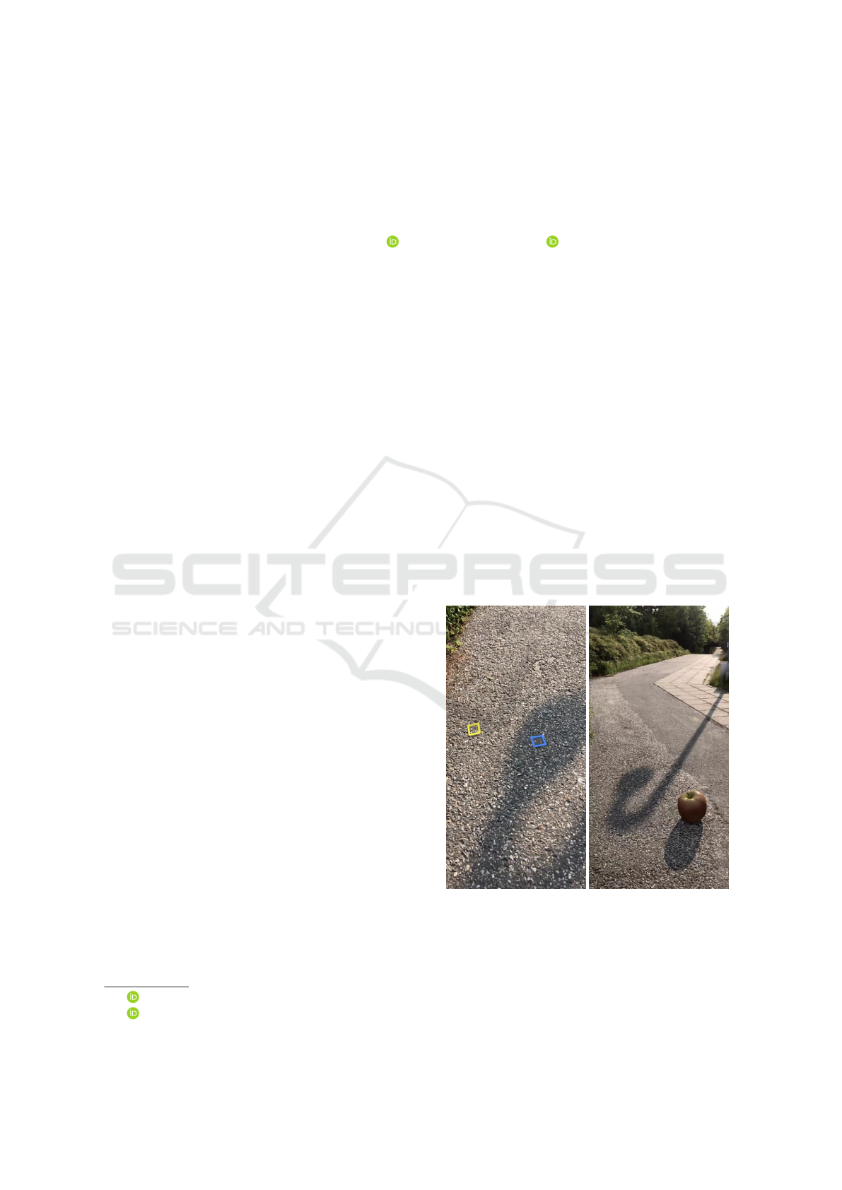
(a) (b)
Figure 1: In our approach the user initially indicates a sun-
lit area and a shadow area in the scene, (a). After that, the
proposed approach renders augmentations, in this case an
apple, while continuously adapting to the illumination con-
ditions of the scene to achieve visually consistent color bal-
ance and depth of shadow areas, (b).
Bertolini, F. and Madsen, C.
Outdoor Illumination Estimation for Mobile Augmented Reality: Real-time Analysis of Shadow and Lit Surfaces to Measure the Daylight Illumination.
DOI: 10.5220/0008943002270234
In Proceedings of the 15th International Joint Conference on Computer Vision, Imaging and Computer Graphics Theory and Applications (VISIGRAPP 2020) - Volume 1: GRAPP, pages
227-234
ISBN: 978-989-758-402-2; ISSN: 2184-4321
Copyright
c
2022 by SCITEPRESS – Science and Technology Publications, Lda. All rights reserved
227

of the virtual objects respond in real-time to fast dy-
namic changes in the illumination of outdoor scenar-
ios, as it could be a cloud temporarily occluding the
sun. In addition, it does not require any presence of
known objects in the environment nor previous train-
ing demanding ground truth datasets. However, some
limits are introduced to simplify the problem state-
ment scope and the final solution: it is restricted to
outdoor environments and it requires a brief user ini-
tialization.
The user input consists in the selection, through
touches on the screen showing the camera feed, of
small area surfaces (referred as patches from now on)
that will be captured in pairs. Each patch will be
tracked during the AR session, thanks to the function-
alities of plane recognition and pose tracking avail-
able in Apple ARKit and Google ARCore frame-
works. Each of these pairs links two patches referring
to the same material, where one of them is lit by the
sunlight and a shadow is cast on the other (thus being
illuminated only from indirect lighting). Having setup
one or more pairs of patches as initialization, the sys-
tem will be able to sample pixel values during the AR
application execution, that will be used to estimate the
overall illumination present in the environment (Fig-
ure 1).
2 RELATED WORK
Accurate light measurements are well established in
the literature thanks to image-based techniques mak-
ing use of light probes. Light probes convey the
information about the incident light on a 3D point
or surface and there exist different kinds: 1) a mir-
rored sphere (Debevec, 1998), 2) a multi-camera sys-
tem (Walton and Steed, 2018), 3) an omni-directional
camera (Stumpfel et al., 2006) or 4) an objects which
albedo and/or shape is priorly known (Knorr and
Kurz, 2014; Hara et al., 2005). Light probes tech-
niques yield precise measurements but the limitation
of having specific objects or additional equipment is
not suitable for a general mobile AR scenario, where
only a Low Dynamic Range (LDR) single view image
from a handheld camera would be available. There
are other ways of computing light information with-
out light probes, but they are computationally heavy,
preventing them to be run in real-time (Lopez-Moreno
et al., 2010; Lopez-Moreno et al., 2013).
To bypass this limitation, some literature sug-
gests to take advantage of Neural Networks, train-
ing them beforehand to compute the lighting informa-
tion from LDR images used as input (Hold-Geoffroy
et al., 2016; LeGendre et al., 2019). While some of
this techniques provides exceptional results on mobile
and in different conditions (outdoor/indoor), it is re-
quired a large data set of examples for the system to be
trained correctly. Other methods instead are based on
direct measurements of radiometric quantities, com-
puting the illumination parameters from the appear-
ance of surfaces already present in the scene (Madsen
and Lal, 2013; Jachnik et al., 2012). The capture of
the light reflected by surfaces provides clues for the
computation of the incident light in real-time. Un-
fortunately they are not designed to be executed on
mobile hardware and much more capable laptop or
desktop Graphical Processing Units (GPUs) are used.
Our work falls within this category as well, but it is
optimized to be fully functional on a mobile device
hardware.
Lastly, an alternative proposal is capable of esti-
mating an outdoor lighting environment with a com-
bination of various indirect measurements such as
live-feed weather forecast, ambient lighting, geo-
localization, date and time (Barreira et al., 2018).
Here the weather predictions are used to define if the
sun is possibly covered by clouds, the ambient light
sensor to predict if the mobile device is sunlit or cov-
ered by a shadow, GPS coordinates and temporal data
to compute the sun direction. The main downside of
this work is that the rotation and position of the hand-
held device will influence the outcome of the light es-
timation, modifying the values recorded by the ambi-
ent light sensor and affecting the lighting of the vir-
tual object. In addition, the weather forecasts do not
include any fast local changes in the sun occlusion.
The work introduced here tries to solve these
problems and poses itself as an improvement on those
weak sides. It is based on the same assumptions
and approach of an already existing shadow analysis
(Madsen and Lal, 2013), but it adds three main con-
tributions to it: 1) we develop the approach so as to
be fast enough for real-time execution on mobile de-
vices, 2) we extend the approach to work with a hand-
held, dynamic camera, rather than a static one, and 3)
propose rendering the estimated sky illumination us-
ing N directional light sources rather than a simple
ambient term to achieve ambient occlusion/contact
shadows. These contributions define this method as
an option to compute outdoor illumination estima-
tion on mobile devices in real-time, performing direct
radiometric measurements, without the need of light
probes nor gathering ground truth data to train the sys-
tem beforehand. In this work we demonstrate that it
is possible to measure an outdoor illumination envi-
ronment with a brief initial user input; future work
will address this constraint, researching how to fully
automate the placement of the patches.
GRAPP 2020 - 15th International Conference on Computer Graphics Theory and Applications
228

3 MATERIALS AND METHODS
3.1 Images as Radiometric
Measurements
To manipulate the information conveyed by an image,
it is necessary to define what a pixel value represents.
Pixels are characterized by triplets of values and from
now on, to simplify the notation, all the color channel
dependent equations will be treated as scalar expres-
sions, since each color channel is independent from
the others.
If light transmission effects, e.g. fog, are ne-
glected, pixel values arising from the projection of a
surface point will depend on three quantities: the bidi-
rectional reflectance distribution function (BRDF) of
the material, the total incident radiance at the surface
point and the camera response function. An essen-
tial hypothesis used in our analytical model is that
the camera response function is linear, hence the val-
ues sampled from the color images are proportional
to the incident radiance on the optic sensors. A non-
saturated pixel value P will then be proportional to
the outgoing radiance from the 3D point represented
by that pixel (Dutr
´
e et al., 2006):
P ∝ L
More specifically, if the camera response function is
defined as c, a generic pixel value representing a point
x is equal to:
P = cL(x → Θ)
where L(x → Θ) is the outgoing radiance from the
point x in the direction of the camera sensor. The out-
going radiance, L(x → Θ), can in turn be expressed
by the material BRDF at the point and the integral of
incoming radiance, L(x ← Ψ), from all directions Ψ
over the hemisphere Ω
x
as defined by the surface nor-
mal direction
ˆ
n at x:
P = c
Z
Ω
x
f
r
(x, Ψ → Θ)L(x ← Ψ)(
ˆ
n ·
ˆ
Ψ)dω
Ψ
(1)
It is assumed that all the materials examined for the
light estimation analysis behave as perfect Lamber-
tian reflectors, defining their BRDF as pure diffuse:
f
r
(x, Ψ ↔ Θ) =
ρ
π
(2)
Even though the BRDF of any material is way more
complex than a simple Lambertian representation,
pure diffuse reflections can be a good approximation
for most of the materials that usually occur in an out-
door scene (grass, concrete, asphalt, etc.). The quan-
tity ρ represents the fraction of incident energy that is
reflected at a surface, it is bounded between 0 and 1
and it is termed the albedo. The integral of all the in-
cident radiance over the hemisphere in Eq. 1 is called
the irradiance, E(x), at x. Therefore Eq. 1 can be
rewritten as:
P = c
ρ
π
E(x) (3)
In an outdoor environment, surface points are illumi-
nated by the sun and by the sky. The total irradiance,
E(x), will thus have two contributions: one from the
sun, E
sun
, and one from the sky, E
sky
. Following the
method developed in (Madsen and Lal, 2013):
E
sun
= (
ˆ
n ·
ˆ
s)E
⊥
sun
(4)
where E
⊥
sun
is the irradiance from the sun onto a sur-
face with its normal pointing straight into the sun, and
ˆ
s is the unit vector defining the direction from the
surface point to the sun (Figure 2). In addition, due
to Rayleigh scattering theory, the atmosphere is also
illuminated, creating the sky as an important illumi-
nant, the irradiance of which we shall formulate as:
E
sky
= V
s
E
⊥
sky
where V
s
∈ [0, 1] is the fraction of visible the sky from
the examined 3D point and E
⊥
sky
is the irradiance pro-
duced by the sky dome from a surface point with nor-
mal pointing upwards and with no occlusion between
itself and the sky.
The part of the illumination arising from global il-
lumination, i.e., light reflected from other surfaces in
the scene, will be ignored in this analysis. The sky
dome is modelled as an hemispherical light source,
with uniform radiance across all directions, as in
(Madsen and Lal, 2013). The total irradiance, E
tot
,
caused by the sun and the sky is thus:
E
tot
= E
sun
+ E
sky
= (
ˆ
n ·
ˆ
s)E
⊥
sun
+V
s
E
⊥
sky
(5)
Now it is possible to express a pixel value recorded by
the camera as a function of the material albedo and the
incident irradiance generated by the sun and the sky:
P = c
ρ
π
[(
ˆ
n ·
ˆ
s)E
⊥
sun
+V
s
E
⊥
sky
] (6)
Figure 2: Outdoor illumination model. The total irradiance
on a surface point will depend on the portion of visible sky
and the angle between its normal and the sun direction.
Outdoor Illumination Estimation for Mobile Augmented Reality: Real-time Analysis of Shadow and Lit Surfaces to Measure the Daylight
Illumination
229

3.2 Irradiance Computation
Eq. 6 correlates a pixel value to the light sources pro-
ducing it, but it is not enough to compute them from
camera measurements. The strategy adopted to do so
is to compare two pixel values corresponding to sur-
faces having the same albedo ρ, but in different light-
ing conditions. It is left to the user to initially identify
two patches of the same material, and it is assumed
material coherence between them. The values used
for the light estimation analysis are the average value
across pixels sampled from each patch. The two pos-
sible lighting conditions in an outdoor environment
are the material lit by the sun and when a shadow is
cast on it. When a surface point is shadowed by an
occluder, the sun contribution is set to zero. Eq. 7
defines the value of the pixel value P
0
representing a
surface in shadow:
P
0
=
ρc
π
[V
0
s
E
⊥
sky
] (7)
Combining Eq. 6 and 7 is possible to extrapolate the
ratio between E
⊥
sun
and E
⊥
sky
:
E
⊥
sun
E
⊥
sky
=
V
0
s
− βV
s
β(
ˆ
n ·
ˆ
s)
(8)
where β is the ratio between P
0
and P. For the final so-
lution of the light estimation analysis, two more quan-
tities needs to be addressed: the visibility of the sky V
s
and the dot product between sun direction and surface
normal (
ˆ
n·
ˆ
s). The sun direction is computed combin-
ing GPS and temporal data (Reda and Andreas, 2004),
and its position relative to the device is maintained
thanks to ARKit pose tracking functionality. Through
ARKit API it is also possible to detect planar surfaces,
which define the normal direction that will be used for
the analysis.
As for the sky visibility coefficient V
s
, in the
present paper the physical 3D environment for the
augmentation is considered to be an horizontal plane,
therefore all surface points are assumed to have a full
sky visibility factor of 1.0. If a 3D model of the envi-
ronment, e.g. a 3D cityscape from Google Earth im-
agery, is available to the application, the sky visibility
can be pre-computed for each point in the scene. If
the 3D model is not available, it could be partly es-
tablished using Structure-from-Motion techniques as
it is already possible on mobiles with some AR en-
gines such as 6D.ai or ARCore Depth API. When a
3D model representing the physical geometry is avail-
able to the application, its contribution for the sky vis-
ibility calculation can be defined sampling the shadow
maps produced by all the light sources representing
the sky illumination. This topic of research is left as a
future improvement, while here we will only demon-
strate the light estimation of a wide open scene. Eq. 8
is very important for the illumination estimation out-
come, but it is not enough: it provides only one equa-
tion and two unknowns (E
⊥
sun
and E
⊥
sky
) for each color
channel.
To overcome this situation, an additional equa-
tion is introduced, based on the white balancing fac-
tor of the camera sensor. This equation is the math-
ematical equivalent of imposing the camera sensor to
be white balanced for horizontal surfaces. Modern
smartphones are very capable of performing real-time
white balancing, and by relying on the smartphone to
automatically keep the video stream white balanced,
we also automatically achieve white balancing on the
estimated illumination, hence the rendered augmen-
tation geometry will be subject to dynamic white bal-
ancing consistent with the real scene. We assume the
camera to be white balanced according to horizontal
surfaces, meaning that the total irradiance on those
surfaces is white balanced. This implies that it exists
a value k that, for each color channel, the following
equation is satisfied:
k = V
wb
s
E
⊥
sky
+ (
ˆ
n
wb
·
ˆ
s)E
⊥
sun
(9)
where V
wb
s
is defined to be the average portion of vis-
ible sky from the horizontal surfaces in the scene, and
ˆ
n
wb
is the normal vector of those surfaces ([0,1,0] in
y-upward coordinate systems). The value of k is de-
fined to be:
k =
πY
ρ
(10)
in which Y is the average relative luminance Y (Eq.
11 (Stone, 2002)) across the entire image and ρ is the
earth’s average albedo, set empirically to 0.25.
Y = 0.2126R + 0.7152G + 0.0722B (11)
Defining k this way, the irradiances of sky and sun
will be proportional to the luminance of the input im-
age, making it possible to run the AR application for
long periods, even with automatic gain control on.
Now that all the quantities are defined, Eq. 8 and Eq.
9 form a system of two equations with two unknowns,
meaning that both sun and sky irradiances can be cal-
culated based on pixel measurements and data gath-
ered with a standard mobile device (an Apple iPhone
7 was used to perform all the computations):
E
⊥
sun
= E
⊥
sky
V
0
s
−V
s
β
(
ˆ
n ·
ˆ
s)β
(12)
E
⊥
sky
=
k
V
s
wb
+
(
ˆ
n
wb
·
ˆ
s)V
0
s
(
ˆ
n·
ˆ
s)(β−V
s
)
(13)
GRAPP 2020 - 15th International Conference on Computer Graphics Theory and Applications
230

3.3 Rendering
Section 3.2 described how to estimate the irradiances
of the sun and the sky using radiometric measure-
ments and geometrical properties of the scene. Given
these irradiance estimates we need to develop a way
to render the virtual models, making their illumina-
tion coherent with the environment they are placed in,
for a real time photo-realistic augmented reality expe-
rience.
In this work the sun is modelled as a directional
light source, which is straightforward to render, in-
cluding a shadow map approach for shadow casting.
Similarly, we propose to approximate the sky (which
in our illumination model is a uniform hemispherical
light source) by a set of N discrete directional lights
which will all contribute as the sky illumination, and
which will all cast shadows using shadow maps (Fig-
ure 3). The advantages of modelling the sky by N
directional light sources rather than a simple ambient
term are threefold: 1) it will provide a much more
realistic shading as compared to combining ambient
occlusion with an ambient term, 2) rendering the N
sources with cast shadows will give the scene very
realistic contact shadows created by the augmented
geometry and 3) occlusions caused by objects out-
side the camera view frustum will be taken into ac-
count, differently than using a Screen Space Ambi-
ent Occlusion approach. In addition the structure of
this methodology is scalable, and the number of direc-
tional light sources can be set according to the capa-
bilities of the hardware, producing better results with
a higher number of light sources.
We have designed and implemented two shaders;
one for shading the augmented geometry, and one for
creating the shadows cast by the augmented geometry
on surfaces of the real scene.
The custom shader for the augmented geometry
is straightforward. The final pixel color is computed
by summing the contributions from each light source,
taking into account shadows, and then multiplying the
total illumination by the albedo of the object as given
by the texture map. The only complicating element is
how to distribute the estimated sky irradiance across
the N directional sources. Assume the N sources are
uniformly distributed over the hemisphere; then the
combined cosine weighting of those sources can be
computed as W =
∑
ˆ
n·
ˆ
l
i
, where
ˆ
n is the normal defin-
ing the hemisphere, and
ˆ
l
i
is the direction vector of
the i-th sky source. The contribution from all sources
can then be combined:
P =
ρ
π
[σ
s
(
ˆ
n ·
ˆ
s)E
⊥
sun
+
∑
σ
i
(
ˆ
n ·
ˆ
l
i
)
1
W
E
⊥
sky
] (14)
where ρ is the albedo coefficient sampled from texture
(a) (b)
Figure 3: Single contributions of the light sources associ-
ated with the sun (a) and the sky (b). The model used for
testing is an apple that was created through photogrammetry
measurements. The vertices produced by the original scan
were decimated and a normal map was generated through a
modelling software
1
.
map of the model, σ
s
∈ {0, 1} is a boolean represent-
ing whether or not the fragment is in shadow from
the sun, and σ
i
∈ {0, 1} similarly represents whether
or not the fragment is in shadow relative to the i-th
sky light source. Eq. 14 only represents the diffuse
part of a standard Phong reflection model; in our ac-
tual implementation we also include a specular part,
although the sky light sources are not allowed to pro-
duce specular contributions.
The other shader in the custom lighting system is
the one applied to the geometry that models the phys-
ical surfaces surrounding the user. The shader com-
putes the possible appearance change of points of the
real scene as a result of virtually adding the augmen-
tation geometry to the scene, i.e., whether or not the
points are now in shadow, and if so, then what is their
new appearance. This is accomplished by multiplying
the pixel values from the video stream with the ratio
of received total irradiance prior to augmentation to
received total irradiance after augmentation. Using
superscript star to indicate quantities relating to prior
to augmentation:
P = P
∗
σ
s
(
ˆ
n ·
ˆ
s)E
⊥
sun
+
∑
σ
i
(
ˆ
n ·
ˆ
l
i
)
1
W
E
⊥
sky
σ
∗
s
(
ˆ
n ·
ˆ
s)E
⊥
sun
+V
∗
s
E
⊥
sky
(15)
This way shadows cast by the sun and the N direc-
tional sky sources are able to lower the intensity of
scene points. And not only does this approach allow
for shadows being cast on real surfaces; the color bal-
ance in the shadows will also mimic the real shadows
correctly, as the color balances of the various light
sources are consistent with the real scene.
1
All 3D models and textures were produced by
Lo
¨
ıc Norgeot (https://sketchfab.com/norgeotloic), ”Low-
poly Fruits” and ”Lowpoly Tools” licensed under CC BY
4.0
Outdoor Illumination Estimation for Mobile Augmented Reality: Real-time Analysis of Shadow and Lit Surfaces to Measure the Daylight
Illumination
231
4 RESULTS
Two main aspects will be discussed: 1) qualitative re-
sults in order to assess the correct blending between
the virtual objects lighting and the natural illumina-
tion and 2) the performance in terms of execution
time.
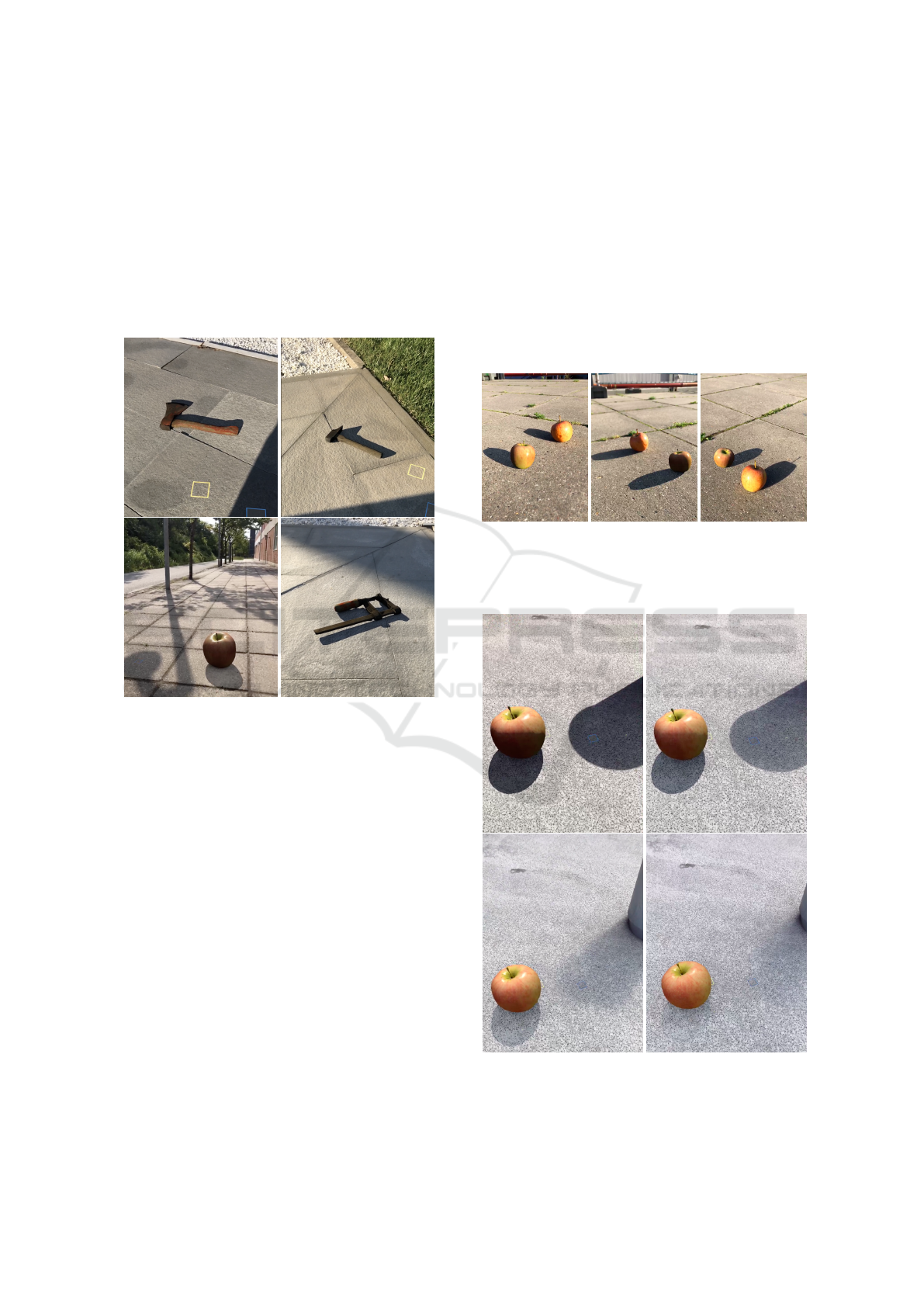
4.1 Qualitative Results
Figure 4: Qualitative results of light estimation performed
during a sunny day and applied to different 3D models.
To evaluate the overall look of the rendered objects,
some example are given next. The images shown in
this section are all screenshots made from an iPhone
7. Figure 4 depicts how the outcome of the light esti-
mation affects the final rendering, providing a photo-
realistic appearance to virtual models placed in the
environment. It is possible to notice the shadow and
lit selected area used to compute the irradiances. This
procedure allows to produce synthetic shadows with
color balance and intensity consistent with the real
ones. Another important cue from Figure 4 is the
presence of a contact shadow where the virtual model
touches the ground, providing an additional realistic
feature to the rendering. Further, the set of pictures in
Figure 5 illustrates the results of the rendering along-
side a real apple, to see how different they look and
to highlight the limits of this technique. The main
issue for a realistic look is the lack of indirect light-
ing on the model surfaces that are not lit by the sun.
This causes a darkening on those surfaces that is not
so deep on the real object. Also the sharp edges of the
model and its shadow make still easy to recognize the
virtual model from the real object.
Lastly, long sequences of light estimation were
recorded during fast changing sky conditions and sun
occlusion. The presence of small and fast chunks
of clouds covering the sun momentarily allowed the
shadows to change in intensity very fast, while per-
forming the light estimation. It is possible to see how
the synthetic shadow adjust automatically to changes
in the illumination, providing a realistic looks to the
scene in real-time. In Figures 6 and 7 the main transi-
tions from two sequences are presented.
(a) (b) (c)
Figure 5: Comparison between a synthetic apple and a real
one. The real apple is on the left side in (b) and on the right
side in (a) and (c).
Figure 6: Sequence of dynamic illumination, the shadow
intensity changes according to the real one.
GRAPP 2020 - 15th International Conference on Computer Graphics Theory and Applications
232
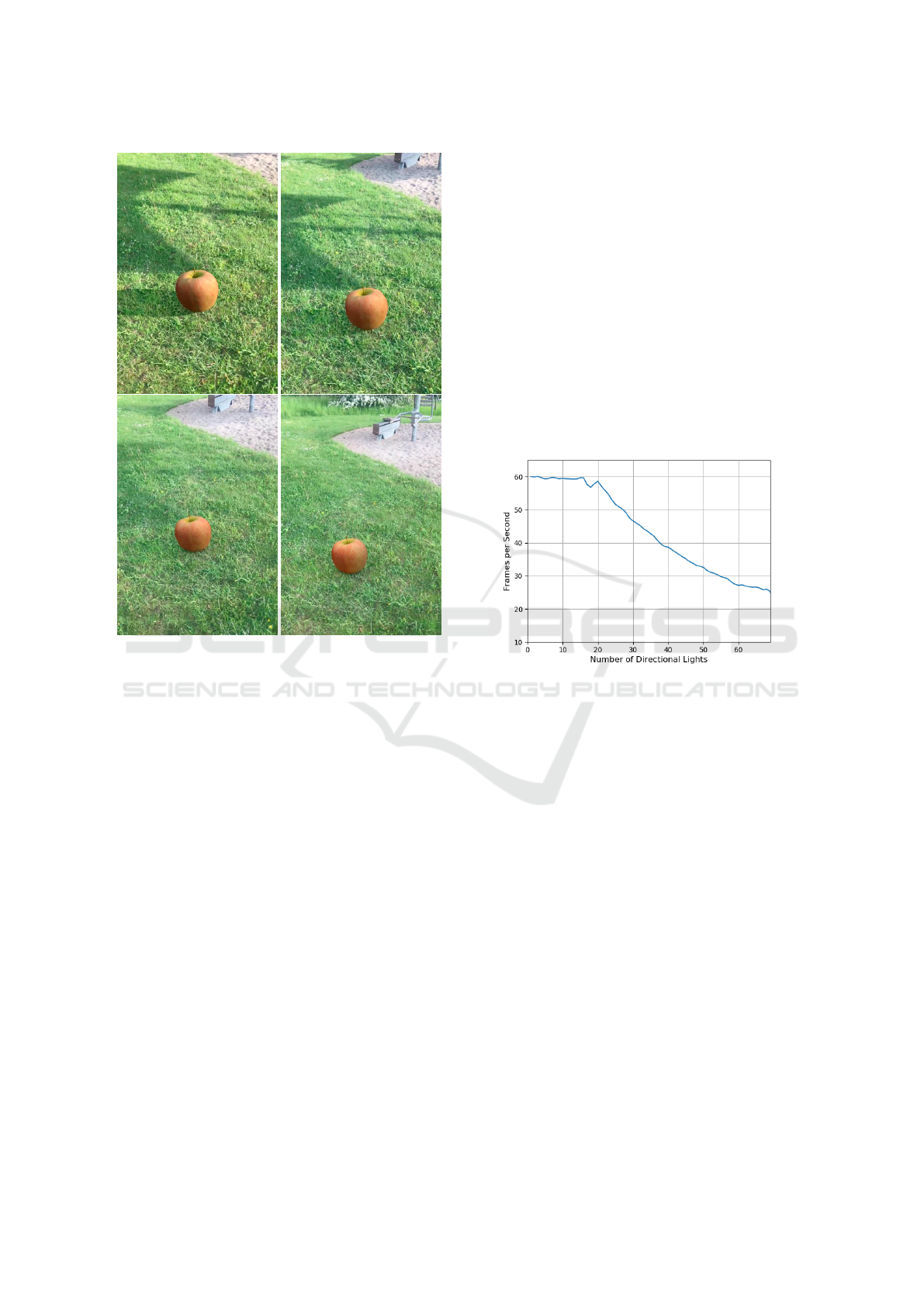
Figure 7: Sequences of dynamic illumination conditions.
The light estimation was performed on grass while the sun
occlusion was varying over time.
4.2 Performance
While in the previous section the qualitative results of
the light were given, here it will be discussed the ef-
ficiency of the algorithm, with a focus on the amount
of time to compute the required values at run time.
The measurements presented in this section are
obtained using an Apple iPhone 7. The main task that
performs the light estimation is split into two compo-
nents: one that deals with the computation of the ir-
radiance values and one that is specifically created to
only compute the average value of the camera color
image. The latter task is completely executed on the
GPU, since its CPU version would cause a significant
bottleneck to the frame execution. To exploit the par-
allelised structure of the graphic hardware, the final
average color of the camera feed is implemented in a
compute shader, that divides the input image in small
chunks of pixels, evaluating each one of them simul-
taneously in separated threads. The total duration of
the algorithm execution is 4.96 ms, where 10,3% of
it is spent on the CPU computations and the 89.7%
is dedicated to execution of the compute shader on
the GPU. The time required to perform the light es-
timation is small enough to allow the application to
execute other processes required for the augmented
reality session to take place.
In addition to the tasks carried out by the engine
to run the AR framework, a part of the frame exe-
cution time is employed by the rendering process. In
this context the rendering is performed using 16 direc-
tional light sources to model the sky contribution; us-
ing more than 16 light sources will improve the over-
all quality of the rendering but will also slow down the
frame rate of the application. Figure 8 shows how the
FPS of the application decreases when adding more
directional lights to the lighting system. The current
version of the rendering system is executed with 17
directional lights, 16 for the sky contribution and 1 to
model the sun illumination.
Figure 8: Measurements of frame-per-second values
while rendering with different numbers of directional light
sources.
5 DISCUSSION
The results demonstrated that it is possible to perform
measurements of the natural light present in outdoor
environments in real time. The approach taken for
the design of the system focused on its execution on
mobile devices with limited computational power.
This was possible introducing approximations on
how light propagates and how the camera measures
physical quantities. The light estimation procedure
has revealed to be a good compromise between pre-
cise measurements and a fast execution. Testing dif-
ferent materials demonstrated the versatility of this
approach to understand the illumination condition,
without the need of placing known objects in the
scene. However, it also highlighted some limitations
given by the low dynamic range of the sensor em-
ployed: saturated pixels are produced only in rare
occasions, but still relevant to the use-case scenario
of this methodology. This pattern is found especially
Outdoor Illumination Estimation for Mobile Augmented Reality: Real-time Analysis of Shadow and Lit Surfaces to Measure the Daylight
Illumination
233

when the sun is very bright and the camera cannot rep-
resent shadow and lit surfaces with significant mea-
surements at the same time.
Furthermore, the selection of shadow and lit
patches is crucial to the light estimation outcome and
a bad positioning would compromise the results. An
automated selection of the area of interest would pre-
vent leaving this task to the user, but a more complex
environment understanding should be employed; the
development of such system is left as a topic for future
research. Another issue that is not possible to over-
come with the presented methodology is the change
in illumination when the patches are not in view to
perform the measurement.
As for the rendering results, this approach to pro-
duce photo-realistic models in real time exhibits that
it is possible to use multiple directional light sources
to simulate an image based lighting technique. Never-
theless, compromises between quality and execution
time must be evaluated in this context as well. As
for the device used during the development, 17 direc-
tional lights yielded an acceptable result, while not
decreasing the frame rate of the application.
In spite of everything, this system poses itself as
an alternative to what is currently available for real
time outdoor lighting estimation on mobile devices.
It demonstrates that it is possible to compute daylight
illumination parameters relying only on sensors avail-
able on the majority of smartphones, performing ra-
diometric measurements and yielding coherent results
between the lighting applied to the virtual models and
the illumination of the environment they are placed
in.
ACKNOWLEDGEMENT
This work is funded by the DARWIN project under
the Innovation Fund Denmark, case number: 6151-
00020B, which is gracefully acknowledged.
REFERENCES
Barreira, J., Bessa, M., Barbosa, L., and Magalhaes, L.
(2018). A context-aware method for authentically
simulating outdoors shadows for mobile augmented
reality. IEEE Transactions on Visualization and Com-
puter Graphics, 24(3):1223–1231.
Debevec, P. (1998). Rendering synthetic objects into real
scenes. In Proceedings of the 25th annual confer-
ence on Computer graphics and interactive techniques
- SIGGRAPH98. ACM Press.
Dutr
´
e, Ph., Bala, K., Bekaert, Ph., and Shirley, P. (2006).
Advanced Global Illumination. AK Peters Ltd.
Hara, K., Nishino, K., and lkeuchi, K. (2005). Light source
position and reflectance estimation from a single view
without the distant illumination assumption. IEEE
Transactions on Pattern Analysis and Machine Intel-
ligence, 27(4):493–505.
Hold-Geoffroy, Y., Sunkavalli, K., Hadap, S., Gambaretto,
E., and Lalonde, J.-F. (2016). Deep outdoor illumina-
tion estimation. 2017 IEEE Conference on Computer
Vision and Pattern Recognition (CVPR), pages 2373–
2382.
Jachnik, J., Newcombe, R. A., and Davison, A. J. (2012).
Real-time surface light-field capture for augmentation
of planar specular surfaces. In 2012 IEEE Interna-
tional Symposium on Mixed and Augmented Reality
(ISMAR). IEEE.
Knorr, S. B. and Kurz, D. (2014). Real-time illumination
estimation from faces for coherent rendering. In 2014
IEEE International Symposium on Mixed and Aug-
mented Reality (ISMAR). IEEE.
LeGendre, C., Ma, W.-C., Fyffe, G., Flynn, J., Charbon-
nel, L., Busch, J., and Debevec, P. (2019). Deeplight:
Learning illumination for unconstrained mobile mixed
reality. In The IEEE Conference on Computer Vision
and Pattern Recognition (CVPR).
Lopez-Moreno, J., Garces, E., Hadap, S., Reinhard, E., and
Gutierrez, D. (2013). Multiple light source estima-
tion in a single image. Computer Graphics Forum,
32(8):170–182.
Lopez-Moreno, J., Hadap, S., Reinhard, E., and Gutierrez,
D. (2010). Compositing images through light source
detection. Computers & Graphics, 34(6):698–707.
Madsen, C. B. and Lal, B. B. (2013). Estimating outdoor il-
lumination conditions based on detection of dynamic
shadows. In Communications in Computer and Infor-
mation Science, pages 33–52. Springer Berlin Heidel-
berg.
Reda, I. and Andreas, A. (2004). Solar position algorithm
for solar radiation application. Solar Energy, 76:577–
589.
Stone, M. (2002). Field Guide to Digital Color. A. K.
Peters, Ltd., Natick, MA, USA.
Stumpfel, J., Jones, A., Wenger, A., Tchou, C., Hawkins,
T., and Debevec, P. (2006). Direct hdr capture of the
sun and sky. In ACM SIGGRAPH 2006 Courses, SIG-
GRAPH ’06, New York, NY, USA. ACM.
Walton, D. R. and Steed, A. (2018). Dynamic hdr environ-
ment capture for mixed reality. In Proceedings of the
24th ACM Symposium on Virtual Reality Software and
Technology, VRST ’18, pages 18:1–18:11, New York,
NY, USA. ACM.
GRAPP 2020 - 15th International Conference on Computer Graphics Theory and Applications
234
