Removing Reflection from In-vehicle Camera Image
Keisuke Inoue, Fumihiko Sakaue and Jun Sato
Nagoya Institute of Technology, Japan
{inoue@cv., sakaue@, junsato@}nitech.ac.jp
Keywords:
In-vehicle Camera, Reflection Removal, Optical Flow.
Abstract:
When taking images with an in-vehicle camera, objects in the vehicle are often reflected on the windshield due
to sunlight, and they appear in the camera image. Since these reflections cause malfunction of autonomous
driving systems, it is very important to remove the reflections from in-vehicle camera images. Thus, we in this
paper propose a method for separating reflections and background scenes, and for generating images without
reflections. Unlike the existing reflection removal methods, our method conducts the signal separation and the
motion field computation simultaneously, so that we can separate images without using edge information. The
efficiency of the proposed method is demonstrated by comparing with existing state-of-the-art methods.
1 INTRODUCTION
When we look at outdoor scenes through glass win-
dows, we often have reflections from indoor objects
on the glass windows, which make it difficult to see
outdoor scenes. Such reflections cause serious prob-
lems for controlling autonomous vehicles using in-
vehicle cameras. We often have strong reflections
from in-vehicle objects at the windshield on sunny
days, and they appear in images observed by in-
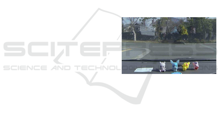
vehicle cameras as shown in Fig. 1. If such a re-
flection occurs, the reflection may be misrecognized
as an object in front of the vehicle, leading to a mal-
function of the autonomous driving system such as an
automatic braking system, which may cause a serious
accident. Thus, we in this paper consider a method
for removing such reflections in images.
In recent years, some methods have been pro-
posed for separating the reflections from the back-
ground scenes in images. Xue et al. (Xue et al., 2015)
used the optical flow estimation for removing reflec-
tion in images, and succeeded to separate complex re-
flections from background scene images. However,
their method requires edge information in images for
estimating optical flows, and thus if the change in
intensity of reflection is not enough, it cannot sepa-
rate image signals properly. More recently, some au-
thors (Fan et al., 2017; Zhang et al., 2018) proposed
reflection removal methods by using a deep learning
technique. Although the efficiency of deep learning
has been shown by these authors, their methods suf-
fer from the domain shift problem, that is if the test
images mismatch the training dataset, their networks
Figure 1: Image captured by in-vehicle camera, which con-
tains reflections on the windshield.
no longer work properly.
Thus, we in this paper propose a new method for
separating reflections and back ground scenes accu-
rately without using edge information and without us-
ing neural networks. The fundamental idea of our
method is to conduct the image signal separation and
the motion field computation simultaneously by min-
imizing a single cost function given a sequence of im-
ages. Although this is a very difficult problem, we
make it tractable by representing the image motion
field parametrically, and by using the property of in-
vehicle camera. That is, the in-vehicle camera is al-
ways fixed at the same position in the passenger com-
partment and does not move relative to the vehicle.
Thus, when taking an image with an in-vehicle cam-
era attached to a running vehicle, the outside scene
moves in the image, but the reflection of objects in
the vehicle does not move. By using these properties,
we separate the outside scene image and the reflected
image from the inside of the vehicle efficiently. Our
222
Inoue, K., Sakaue, F. and Sato, J.
Removing Reflection from In-vehicle Camera Image.
DOI: 10.5220/0008941002220228
In Proceedings of the 15th International Joint Conference on Computer Vision, Imaging and Computer Graphics Theory and Applications (VISIGRAPP 2020) - Volume 4: VISAPP, pages
222-228
ISBN: 978-989-758-402-2; ISSN: 2184-4321
Copyright
c
2022 by SCITEPRESS – Science and Technology Publications, Lda. All rights reserved
method does not rely on edge information in images,
and does not use image prior learned from the train-
ing dataset. Thus, it works properly even if there is
no strong edge information in reflection, and does not
suffer from the domain shift problem.
2 RELATED WORK
In recent years, various approaches have been pro-
posed for image signal separation. These methods fall
into two classes, i.e. single image based methods and
multiple image based methods.
The single image based methods are ill-posed, and
hence it is necessary to combine a priori knowledge in
these methods. Levin et al.(Levin et al., 2004) pro-
posed a technique for separating reflections so that
the brightness gradient of the recovered image ap-
proaches to that of the image in the natural image
database. More recently, deep learning techniques
are used for learning image features of reflection and
separating reflections from images (Fan et al., 2017;
Zhang et al., 2018; Wan et al., 2018). These meth-
ods enable us to separate reflections more accurately
and faster than before. However, since these methods
learn the image features of reflection based only on
the training data, an enormous amount of training data
is required to deal with various types of reflections in
various scenes. As a result, these methods often suffer
from the domain shift problem caused by the limited
number of data. On the contrary, our method is based
on the imaging model of reflection and does not rely
on training dataset, so it does not suffer from the do-
main shift problem.
The multiple image based methods use the prop-
erty that the motion of the background scene is dif-
ferent from that of the reflection on glass windows.
Yu and Brown (Yu and Brown, 2013) proposed a
method for separating images into foreground and
background by matching image features using SIFT.
Xue et al. (Xue et al., 2015) recovered dense motion
fields from sparse motion fields obtained by edge in-
formation, and showed that the dense motion fields
enable us to separate foreground and background im-
ages more accurately. Nandoriya et al. (Nandoriya
et al., 2017) also used image edge information for
obtaining initial motion field and for separating fore-
ground and background information in video frames.
However, all these methods require edge information
for obtaining motion fields in images, and hence they
cannot separate foreground and background informa-
tion accurately, when we do not have abrupt change
in intensity and cannot obtain image features in input
images. On the contrary, our method does not require
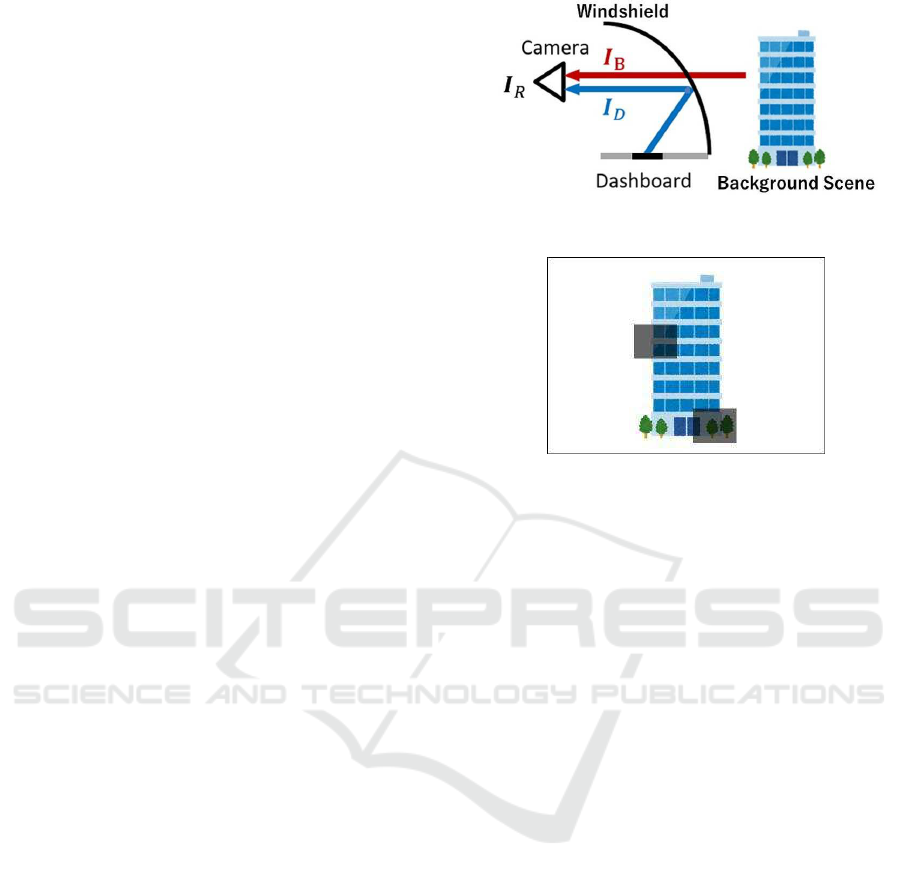
Figure 2: In-vehicle camera observes not only background
scene, but also reflection of objects in vehicle.
Figure 3: Observed image which contains reflection from
objects in vehicle, i.e. two gray squares.
abrupt change in images and does not need to extract
image features for separating image signals.
3 TRANSMISSION AND
REFLECTION
We first consider an imaging model of an in-vehicle
camera, in which reflected light and transmitted light
are simultaneously captured in a single image.
In the image of an in-vehicle camera, we often ob-
serve light reflected by the windshield of the vehicle
I
B
as well as light transmitted through the windshield
I
D
. Fig. 2 shows the scene where two types of light I
B
and I
D
enter the in-vehicle camera, and Fig. 3 shows
observed image I
R
by the camera. The image I
R
in-
cludes regions that are darker than the surrounding
area. This is the reflection caused by objects in the
vehicle.
Xue et al. formulated that the observed image is
expressed by the alpha blending of the background
image and the foreground image at a fixed ratio as
follows:
I
R
(x) = (1− α(x))I
B
(x) + α(x)I
D
(x) (1)
where x = [x, y]
T
is an image pixel, and α(x) denotes
the mixing ratio at x, which ranges from 0 to 1.
It seems that Eq. (1) is correct, but actually it is
physically wrong, since in this model the light I
B
from
the outside of the vehicle is attenuated with (1− α),
which does not happen in reality. Reflection is caused
Removing Reflection from In-vehicle Camera Image
223

(a) Background image (b) reflection image
Figure 4: Background image I
B
and reflection image I
D
derived from the observed image I
R
in Fig. 3.
by the addition of the light I
D
from the inside of the
vehicle to the light I
B
from the outside of the vehi-
cle as shown in Fig. 2, and the light I
B
from the out-
side of the vehicle is not attenuated. Also, for us-
ing this equation, we have to estimate not only two
images, I
B
and I
D
, but also a mixing parameter α,
which is over parameterized for representing reflected
light and transmitted light. Thus, we next consider
an imaging model based on the reflection principle
where light inside the vehicle is added to light outside
the vehicle.
Let us consider the case where light from outside
of the vehicle I
B
and light from inside of the vehicle
I
D
are incident as shown in Fig. 3. If the light I
B
and
the light I
D
are added to form an observed image, the
intensity I
R
of the observed image can be expressed
as follows:
I
R
(x) = I
B
(x) + I
D
(x) (2)
Fig. 4 shows the background image I
B
and the
reflection image I
D
when considered based on this
model. The observed image in Fig. 3 is the sum of
these two images according to Eq.(2). As is clear
from the image in Fig.4 (b), the two gray squares in
the observed image in Fig. 3 is generated not because
the reflection of gray square objects exists, but be-
cause the intensity of the square objects is lower than
the surrounding area. The reflection model in Eq. (2)
accurately models this actual reflection process.
We next consider the difference in the character-
istics of the external image I
B
and in-vehicle image
I
D
over time. In the outside image I
B
, the position of
3D object in the image changes with the motion of the
vehicle, so the brightness I
B
(x) at a pixel x in the im-
age changes with time. On the other hand, since the
object in the vehicle is stationary relative to the in-
vehicle camera, the intensity I
D
(x) of the in-vehicle
image at pixel x can be considered to be constant in a
short period of time.
In the following sections, we propose a method
for separating the outsize image I
B
and the inside im-
age I
D
from the observed image I
R
assuming that the
inside image I
D
is constant in a short period of time.
4 SEPARATING OUTSIDE AND
INSIDE IMAGES
Suppose we have an observed image I
t
B
at time t.
Then, assuming that the optical flow does not change
in a short period of time, the observed image
ˆ
I
s
B
at
time s (s 6= t) can be described by using the observed
image I
t
B
at time t as follows:
ˆ
I
s
B
(I
t
B
, ∆x) = I
t
B
(x− (s− t) · ∆x) (3)
where ∆x denotes the optical flow at x.
Furthermore, we represent the optical flow of
background scene motion parametrically by using
affine transformation, that is affine flow (Sabater et al.,
2012; Ju et al., 1996). In the affine flow, the motion
vector ∆x = [∆x, ∆y]
⊤
at x = [x, y]
⊤
can be described
as follows:
∆x
1
= A
x
1
(4)
A =
a
11
a
12
a
13
a
21
a
22
a
23
0 0 1
(5)
where A denotes affine transformation matrix with six
parameters, and we represent the whole optical flow
in the image just by these six parameters. It seems that
six parameters are not enough for representing whole
scene flow. However, since the affine flow can repre-
sent divergence as well as rotation and translation, it
can describe scene flow of in-vehicle camera images
efficiently.
Now, let us consider three consecutive images,
I
0
R
(x), I
1
R
(x) and I
2
R
(x). From Eq. (3), these three im-
ages can be described by using reflection image I
D
,
affine parameter A and background image I
0
B
at time
0 as follows:
I
0
R
(x) =
ˆ
I
0
B
(I
0
B
, ∆x(A)) + I
D
(x) (6)
I
1
R
(x) =
ˆ
I
1
B
(I
0
B
, ∆x(A)) + I
D
(x) (7)
I
2
R
(x) =
ˆ
I
2
B
(I
0
B
, ∆x(A)) + I
D
(x) (8)
where ∆x(A) denotes motion vector at x in the affine
flow represented by an affine transformation matrix
A. Assuming that ∆x(A) does not change even if the
background images change in a short time, we can ob-
tain constraints on optical flow in the background im-
age. As a result, we can describe a series of observed
images I
t
R
(t = 0, ··· , 2)using a background image I
0
B
,
a reflection image I
D
and an affine transformation A.
Since the observed images I
t
R
at three consecutive
time are represented as shown in Eq. (6), Eq. (7) and
Eq. (8), we can estimate I
0
B
, I
D
and A by minimizing
the following cost function E
c
:
E
c
(I
0
B
, I
D
, A) =
2
∑
t=0
||I
t
R
−
ˆ
I
t
B
(I
0
B
, A)− I
D
||
2
(9)
VISAPP 2020 - 15th International Conference on Computer Vision Theory and Applications
224
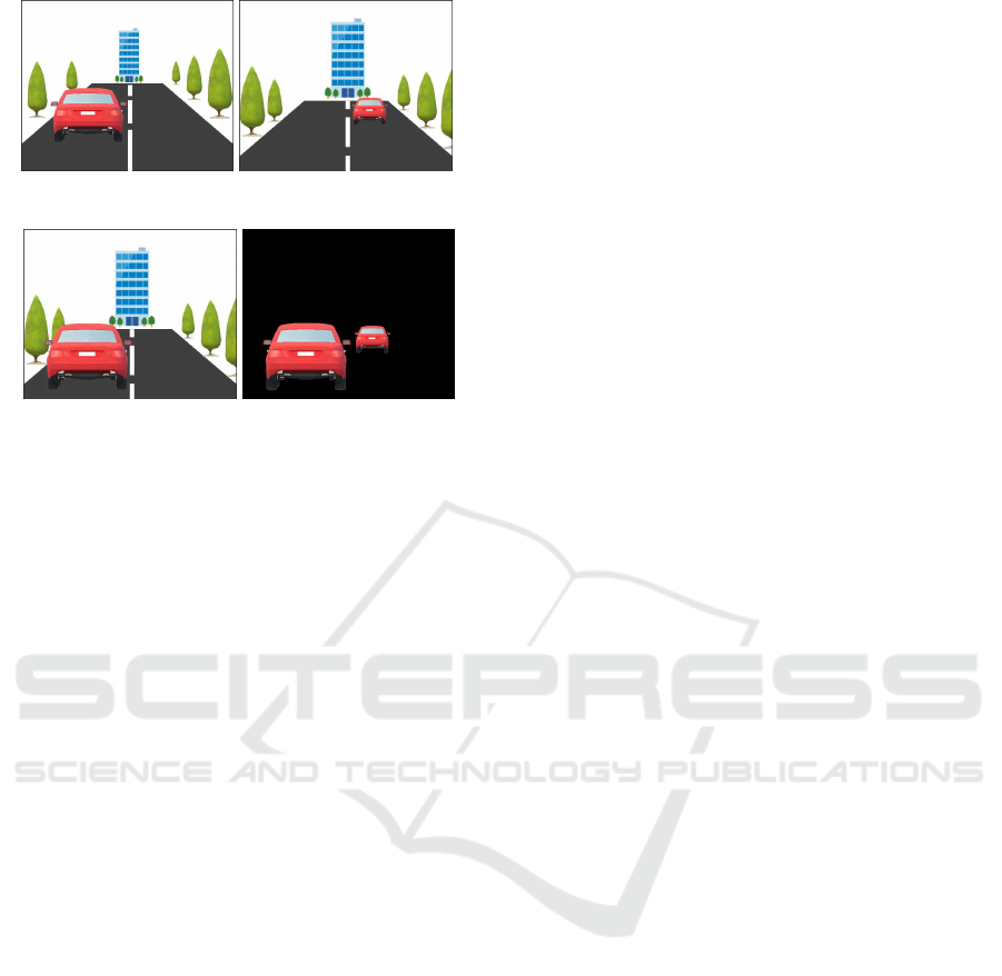
(a) Background image I
0
B
(b) Background image I
1
B
(c) Synthesized image
ˆ
I
1
B
(d) ||I
1
B
−
ˆ
I
1
B
||
Figure 5: Separating images under the existence of inde-
pendent motions.
In Eq.(9), we use three observations I
t
R
(t = 1, ··· , 2),
since we estimate two images, I
0
B
and I
D
, and an affine
transformation.
5 SEPARATING IMAGES UNDER
INDEPENDENT MOTIONS
In section 4, we estimated outside image I
B
and inside
image I
D
by assuming that the entire optical flow in
the image can be represented by a single affine trans-
formation. Although this assumption is valid when
we observe a static scene from a moving vehicle, it is
no loner valid if we have some independently mov-
ing objects in the scene. Thus, in this section, we ex-
tend the method described in section 4, and propose
a method for extracting outside image and inside im-
age from the observed image under the existence of
multiple independent motions.
Suppose we have background images, I
0
B
and I
1
B
and affine flow A which are obtained by using the pro-
posed method, as shown in Fig. 5 (a) and (b). Then
the background image
ˆ
I
1
B
can be synthesized by us-
ing I
0
B
and A according to Eq. (3) as shown in Fig. 5
(c). Since the affine flow A represents the background
scene motion, the static objects, such as buildings and
trees, in I
1
B
and
ˆ
I
1
B
coincide with each other. However,
if we have independently moving objects, such as ve-
hicles, they do not match in I
1
B
and
ˆ
I
1
B
as shown in
Fig. 5 (b) and (c). Thus, we can extract independently
moving regions as shown in Fig. 5 (d) by extracting
image pixels which hold the following inequality:
||I
1
B
−
ˆ
I
1
B
(I
0
B
, A)|| ≥ th (10)
where, th is a threshold value. Then, by minimizing
the cost function E
c
on this region, the outside im-
age I
B
and the inside image I
D
as well as the affine
flow A of the independently moving region can be
obtained. By applying these procedures iteratatively,
we can extract outside images and inside images from
captured images. Hence, we extract outside image
I
B
, inside image I
D
and affine flows of N regions
A
R
= { A
1
, ··· , A
N
} by solving the following mini-
mization problem:
{
ˆ
I
0
B
,
ˆ
I
D
,
ˆ
A
R
} = arg min
I
0
B
,I
D
,A
R
N
∑
i=1
E
c
(I
0
Bi
, I
Di
, A
i
)
+ α||L (I
0
B
)||
2
+ β||L (I
D
)||
2
(11)
where, L (·) denotes the Laplacian for smoothness
constraints, and α and β is its weight.
6 SEGMENTATION IMAGE
For separating outside and inside images more accu-
rately, we further introduce image segmentation into
our method.
In Sec 2.2, we assumed that the intensity of the
outside image changes with time, while that of the
inside image does not change. However in the real
scene image, the image motions of some outside ob-
jects, such as road, are not observable since they do
not have enough texture on their surface. As a result,
these objects are classified into inside objects and ap-
pear in the inside image. For solving this problem, we
utilize image segmentation, and set additional con-
straints to be classified into inside intensity when the
image point belongs to texture-less objects.
More specifically, we first classify image pixels in
an image into four categories, “Buildings”, “Road”,
“Sky”, and “Others” by using an image segmenta-
tion network, and “Buildings”, “Road” and “Sky” are
marked as texture-less area. We next define a maxi-
mum intensity I
max
D
(x) for inside image I
D
at an image
pixel x as follows:
I
max
D
(x) = λI
R
(x) (12)
where, λ is a scalar in the range of [0, 1]. If an im-
age pixel x is in a texture-less area, then inside im-
age intensity I
D
(x) at x is estimated in the range of
[0, I
max
D
(x)], and if x is not in a texture-less area, I
D
(x)
is estimated in the range of [0, 1] by using Eq.(11). In
this way, we can avoid outside objects, such as road
and sky, being classified as inside objects and appear-
ing in the inside image. Fig. 6 shows an overview of
this algorithm.
Removing Reflection from In-vehicle Camera Image
225
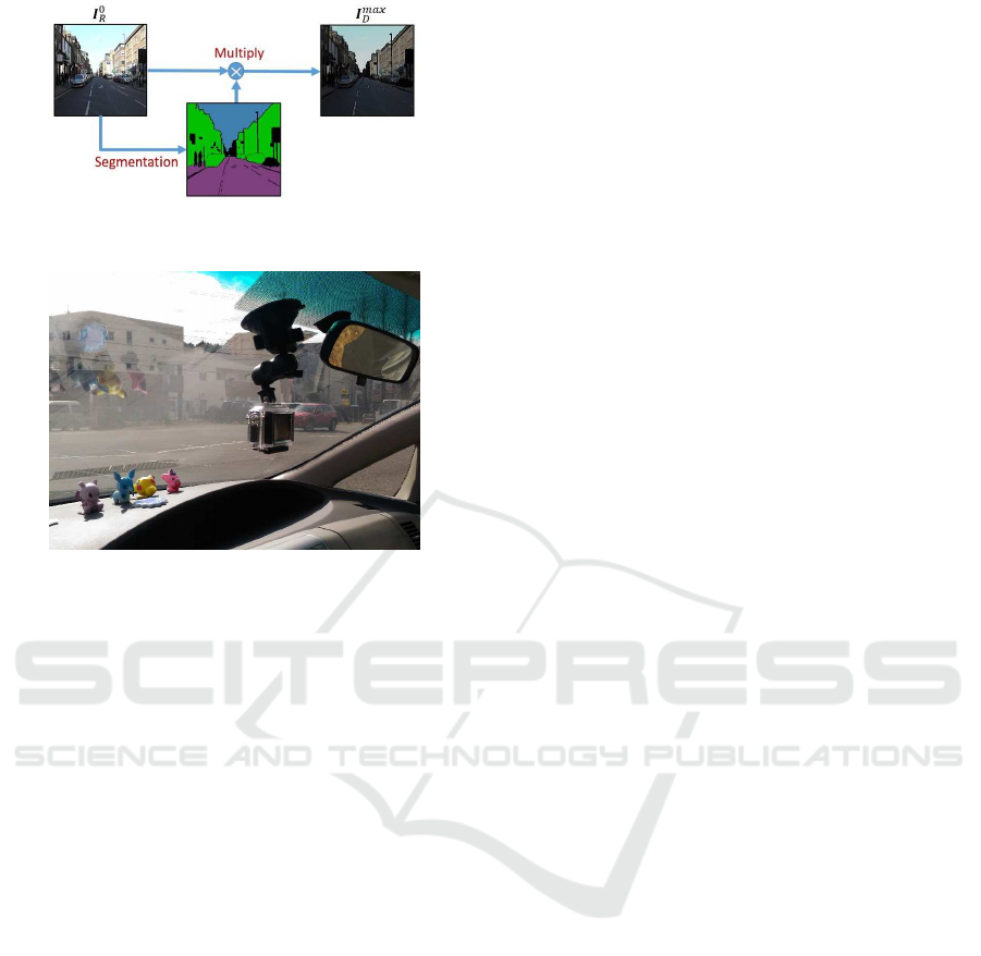
Figure 6: Overview of generating I
max
D
(x) for a texture-less
area.
Figure 7: Experimental setup of in-vehicle camera and re-
flection on windshield.
7 EXPERIMENTS
We next show the results of generating reflection re-
moval images using our proposed method in various
scenes.
In our experiments, road scene images were taken
by an in-vehicle camera. As shown in Fig. 7, the
in-vehicle camera was attached on the windshield
so that the reflection from the object on the dash-
board appears in the image. We took three con-
secutive images every 0.1 seconds in the driving
scene, and cropped these images with the size of
200 × 200. To obtain the segmentation images, we
used a standard image segmentation network based
on pix2pix (Isola et al., 2016), which was trained on
Cityscapes dataset (Cordts et al., 2016).
Fig. 8 (a), (b) and (c) showthree sequential images
of four difference scenes observed by the in-vehicle
camera. As shown in these images, inside objects
were reflected by the windshield and appear in the ob-
served images with outside scenes. These sequential
images were used for extracting outside image and in-
side image. The outside and inside images obtained
from our method are shown in Fig. 8 (d) and (e) re-
spectively. As shown in these images, outside scenes
and inside objects are separated appropriately in these
images by using our method. Fig. 8 (f) shows op-
tical flow estimated by our method. As we can see
in these images, the estimated optical flow represents
the movement of the buildings, road and trees appro-
priately.
We next compare our method with two state-of-
the art reflection removal methods. The first one is
Xue’s method (Xue et al., 2015) which uses edge in-
formation for computing optical flows and separat-
ing signals. This method can separate signals clearly
when we have sharp reflection in images, but it de-
grades when the reflected objects are vague in im-
ages. The second one is Zhang’smethod (Zhang et al.,
2018) which is based on a trained neural network.
Fig. 9 compares the results of our method with
those of Xue’s method and Zhang’s method. As
shown in this figure, Xue’s method cannot remove
the reflection properly, since the reflected objects do
not have sharp edges in the observed images, and the
motion field cannot be obtained accurately in their
method. Zhang’s method succeeded to remove re-
flection partially, but not all of the reflection was re-
moved accurately. Since the efficiency of learning
based methods heavily depends on the dataset used
in the learning stage, Zhang’s method cannot remove
reflection accurately, when the input images are taken
under different domains.
Finally, we show results from images which con-
tain independent motions. Fig. 10 (a) show sequential
images at t = 0 and t = 2. As shown in these im-
ages, the vehicle is moving forward while the bicycle
and the pedestrian are moving independently. Fig. 10
(b) shows reflection removal images obtained from
the proposed method, and Fig. 10 (c) shows optical
flow estimated at the same time. As shown in Fig. 10
(b), the reflection at the center of the image was elimi-
nated accurately even if we have independent motions
in images. Fig. 10 (c) shows that both the background
scene motions and the independent motions are esti-
mated accurately in the proposed method.
From these results, we find that the proposed
method works efficiently under various situations.
8 CONCLUSIONS
In this paper, we proposed a novel method for sepa-
rating background scenes and reflections from images
observed by an in-vehicle camera.
Our method estimates background scene images,
reflection images and scene flows simultaneously,
representing the scene flows parametrically by using
affine transformations. The method does not reply on
edge information in images, and hence it works effi-
ciently even if the reflections do not have sharp image
features unlike the existing methods.
VISAPP 2020 - 15th International Conference on Computer Vision Theory and Applications
226
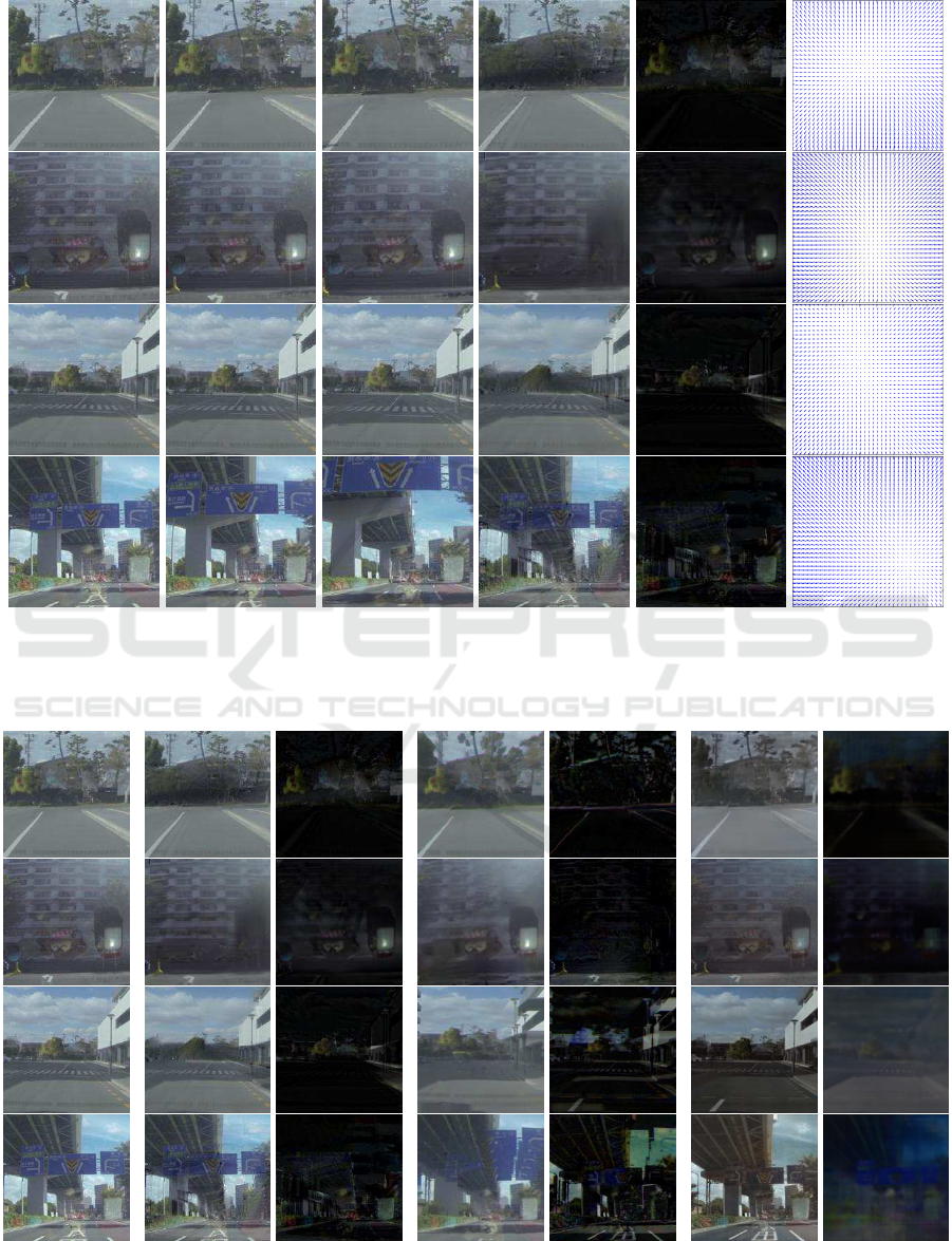
(a) t = 0 (b) t = 1 (c) t = 2 (d) outside (e) inside (f) flow
Figure 8: Result of signal separation from in-vehicle image into outside image and inside image. (a), (b) and (c) show three
sequential images obtained by in-vehicle camera. (d) and (e) show outside image and inside image obtained by the proposed
method from images in (a), (b) and (c). The estimated optical flow is shown in (f).
(a)Input (b)Our results (c)Xue’s method (d)Zhang’s method
Figure 9: Comparison of reflection removal images obtained by our proposed method, Xue’s method (Xue et al., 2015) and
Zhang’s method (Zhang et al., 2018).
Removing Reflection from In-vehicle Camera Image
227
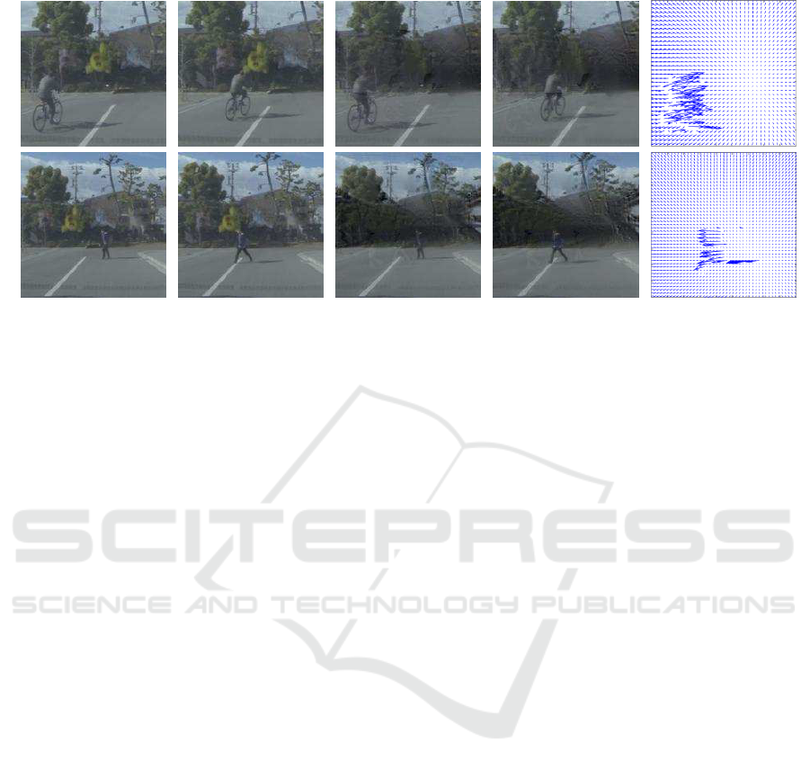
(a) input image (b) reflection removal image (c) optical flow
test scene 1test scene 2
t=0 t=2 t=0 t=2
Figure 10: Results of generating reflection removal image and computing optical flow under the existence of independent
motions.
The experimental results show that the pro-
posed method outperforms the existing state-of-the-
art methods.
REFERENCES
Cordts, M., Omran, M., Ramos, S., Rehfeld, T., Enzweiler,
M., Benenson, R., Franke, U., Roth, S., and Schiele,
B. (2016). The cityscapes dataset for semantic urban
scene understanding. In Proc. of the IEEE Conference
on Computer Vision and Pattern Recognition (CVPR).
Fan, Q., Yang, J., Hua, G., Chen, B., and Wipf, D. (2017).
A generic deep architecture for single image reflection
removal and image smoothing. In Proceedings of the
IEEE International Conference on Computer Vision,
pages 3238–3247.
Isola, P., Zhu, J.-Y., Zhou, T., and Efros, A. A. (2016).
Image-to-image translation with conditional adversar-
ial networks. arxiv.
Ju, S. X., Black, M. J., and Jepson, A. D. (1996). Skin
and bones: Multi-layer, locally affine, optical flow
and regularization with transparency. In Computer
Vision and Pattern Recognition, 1996. Proceedings
CVPR’96, 1996 IEEE Computer Society Conference
on, pages 307–314. IEEE.
Levin, A., Zomet, A., and Weiss, Y. (2004). Separating
reflections from a single image using local features.
In ECCV.
Nandoriya, A., Elgharib, M., Kim, C., Hefeeda, M., and
Matusik, W. (2017). Video reflection removal through
spatio-temporal optimization. In The IEEE Interna-
tional Conference on Computer Vision (ICCV).
Sabater, N., Leprince, S., and Avouac, J.-P. (2012). Con-
tract invariant and affine sub-pixel optical flow. Inter-
national Conference on Image Processing.
Wan, R., Shi, B., Duan, L.-Y., Tan, A.-H., and Kot, A. C.
(2018). Crrn: Multi-scale guided concurrent reflection
removal network. In Proceedings of the IEEE Con-
ference on Computer Vision and Pattern Recognition,
pages 4777–4785.
Xue, T., Rubinstein, M., Liu, C., and Freeman, W. T.
(2015). A computational approach for obstruction-
free photography. ACM Transactions on Graphics
(Proc. SIGGRAPH), 34(4).
Yu, L. and Brown, M. (2013). Exploiting reflection change
for automatic reflection removal. pages 2432–2439.
Zhang, X., Ng, R., and Chen, Q. (2018). Single image re-
flection separation with perceptual losses. In Proceed-
ings of the IEEE Conference on Computer Vision and
Pattern Recognition, pages 4786–4794.
VISAPP 2020 - 15th International Conference on Computer Vision Theory and Applications
228
