Patient Motion Compensation for Photogrammetric Registration
Hardik Jain
1 a
, Olaf Hellwich
1
, Andreas Rose
2
, Nicholas Norman
2
, Dirk Mucha
2
and Timo Kr
¨
uger
2
1
Department of Computer Vision & Remote Sensing, Technische Universit
¨
at Berlin, Germany
2
Fiagon GmbH, Germany
Keywords:
Visual Structure from Motion, Dynamic Scene, Motion Compensation, Photogrammetric Registration.
Abstract:
Photogrammetry has evolved as a non-invasive alternative for various medical applications, including co-
registration of the patient at the time of a surgical operation with pre-surgically acquired data as well as
surgical instruments. In this case body surface position regularly has to be determined in a global co-ordinate
system with high accuracy. In this paper, we treat this task for multi-view monocular imagery acquiring both
body surface as well as e.g. reference markers. To fulfill the high accuracy requirements the patient is not
supposed to move while images are taken. An approach towards relaxing this demanding situation is to mea-
sure small movements of the patient, e.g. with help of an electromagnetic device, and to compensate for the
measured motion prior to body surface triangulation. We present two approaches for motion compensation:
disparity shift compensation, and moving cameras compensation - both capable of achieving patient registra-
tion qualitatively equivalent to motion-free registration.
1 INTRODUCTION
In surgical applications precise positioning of a navi-
gation instrument is essential to carry out a successful
surgery. In some cases, such as nasal surgery, non-
invasive methods are used to establish a registration
between pre-surgical data such as computed tomogra-
phy (CT) data and the patient’s surface. In this work,
photogrammetric reconstruction is used for this pur-
pose. Besides the co-ordinate systems of photogram-
metric surface reconstruction and pre-surgical data,
the co-ordinate system of the navigated instrumenta-
tion is of importance in this setting. Usually, the latter
is defined by electromagnetic field emitter. The refer-
ence between the co-ordinate system of a photogram-
metric reconstruction and the pre-surgical co-ordinate
system is established via the patient’s body surface,
e.g. the facial surface, which is available in both pho-
togrammetric imagery as well as pre-surgical data.
The reference from photogrammetric co-ordinates to-
wards electromagnetic co-ordinate system of the nav-
igation device can be established via visible reference
markers that can both be photogrammetrically recon-
structed as well as electromagnetically tracked. If the
photogrammetric imagery is acquired by a monoc-
ular camera, a pre-requisite for a successful patient
co-registration is a static (motionless) arrangement of
patient surface and reference marker ensemble while
images are taken. This is potentially difficult for the
a
https://orcid.org/0000-0001-9499-8040
patient to achieve, in particular if required to sit with-
out anesthesia e.g. in a dental chair being less stable
than lying with anesthesia on a surgical table. Then
measuring patient motion that occurs in-between im-
age shots is a reasonable idea to compensate for mo-
tion. This is particularly appropriate, if the patient’s
body is already tracked electromagnetically in order
to allow patient motion after co-registration to pre-
surgical data has been established.
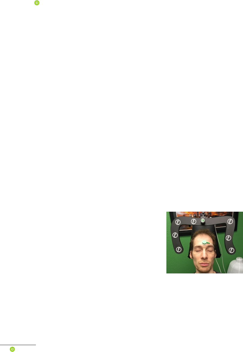
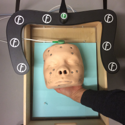
Figure 1: A seated patient next to a mapper frame carry-
ing an ensemble of reference markers. The electromagnetic
patient localizer, a device which provides position and ori-
entation in electromagnetic co-ordinate system, on the fore-
head (in green) is used to track the head motion relative
to the mapper frame while several photogrammetric images
are acquired.
This setting is treated in this paper: monocular
“visual structure-from-motion” (VSfM) surface re-
construction is done for both, patient’s body surface
as well as an ensemble of reference markers located
on a mapper frame next to the patient (Fig. 1). While
the patient may unwillingly conduct small motions
w.r.t. the marker ensemble, the required high preci-
sion of patient co-registration prohibits such motion.
Motion is, therefore, compensated for by measuring
patient’s movement electromagnetically and calculat-
ing its influence on stereoscopic matching.
In order to allow navigated surgery, the surgical
navigation system needs to co-register the patient’s
facial surface at the time of the operation with pre-
surgically acquired data. The patient’s facial surface
is acquired by stereo photogrammetry in co-ordinates
of the mapper frame (shown in Fig. 1, bearing the
reference markers). The facial surface is also con-
tained in the 3D pre-surgical data. It is matched with
the photogrammetric facial surface. The matching of
the two surfaces is the measurement providing the re-
quired co-registration information.
In an online data acquisition the quality of co-
registration can be tested using an electromagnetic
touch-based pointer device on the patient’s facial sur-
face as long as he/she remains in the operational set-
ting with the electromagnetic forehead patient local-
izer unchanged (Fig. 1). During a check the local-
izer’s position is superimposed to the pre-surgical
face surface on the display. In other words, the
touch-pointer device coordinates are transformed to
the pre-surgical surface from electromagnetic touch-
pointer localizer co-ordinate system via electromag-
netic field emitter, electromagnetic mapper-frame lo-
calizer, marker-based optical mapper frame defini-
tion, photogrammetric facial surface reconstruction,
and facial surface matching solution towards the co-
ordinate system of the pre-surgical data. So a concate-
nated transformation involving six coordinate systems
is conducted. The procedure includes calibration data
of different devices, e.g. calibration data of the touch-
pointer device, or of the mapper frame.
After photogrammetric co-registration with the
pre-surgical data has been conducted, the continued
online measurements of the patient localizer allow
movements of the patient during the operation with-
out loosing reference between pre-surgical and actual
facial surface. The difference between patient local-
izer during photogrammetric acquisition and patient
localizer at any other time (e.g. at time of check with
the electromagnetic touch-based pointer) is taken into
account by the transformation difference between cur-
rent patient localizer coordinate system and patient
localizer coordinate system at the time of photogram-
metric image acquisition.
We focus on the elimination of patient motion ef-
fects that occur in-between the acquisitions of the
first and the subsequent monocular images used for
photogrammetric surface reconstruction. Compensa-
tion of these motions is both essential for geometri-
cally accurate “visual structure from motion” recon-
struction as well as uncommon in standard processing
chains, which is why it is subject of this paper.
The rest of the paper in organised as follows: In
the next section, some of the related previous works
are discussed along with an outline of how our ap-
proach is different to them. In Section 3, the two ap-
proaches to motion compensation, and the impact of
no compensation are discussed. Experimental find-
ings on phantom and real patient are presented in Sec-
tion 4. Finally, in Section 5 the paper is concluded.
2 RELATED WORK
The inverse problem of 3D surface reconstruction
from multiple images is fundamental in computer vi-
sion. Solutions to this VSfM task can be found in
literature as early as in the 1980’s (Ullman, 1979;
Grimson, 1981). Initially, the field was dominated by
sparse feature-based reconstruction (Hartley and Zis-
serman, 2003). Over the years, with the surge in com-
putational resources, dense 3D reconstruction was in-
troduced (Furukawa and Ponce, 2009), and demon-
strated (Newcombe et al., 2015). Dense surface re-
construction from multiple images forms the back-
bone for various modern computer vision applica-
tions.
The improvements in the solution of the inverse
3D problem also led to its application in medical do-
main. In medicine, it is widely used as low-cost non-
invasive alternative for accurate and external mea-
surements. Recently, to investigate cranial deforma-
tion in infants, Barbero-Garc
´
ıa et al. (2019) proposed
use of smartphone-based photogrammetric 3D head
modelling. A video stream was recorded so as to ob-
tain 200-300 images, which were then used to create
a 3D head model. The accuracy of the photogram-
metric model was comparable to a radiological cra-
nial 3D model. A survey by Ey-Chmielewska et al.
(2015) highlights the application of photogrammetry
in screening tests of spinal curvature, ophthalmology,
dermatology, dentistry and orthodontics.
In the medical field, application of photogramme-
try is not restricted to external measurements and is
often used in planning and monitoring of surgeries.
This involves registration of available pre-surgical 3D
data with online-acquired data. Co-registration before
and during treatment is generally achieved by image-
based techniques. Registration of patient’s face sur-
face with pre-surgical data was utilized in navigated
surgery (Hellwich et al., 2016). For accurate localiza-
tion of EEG electrodes, photogrammetry-based head
digitization was adopted in Clausner et al. (2017).
Salazar-Gamarra et al. (2016) used mobile-phone im-
ages to obtain 3D model for facial prosthesis. In these
applications, to reduce motion distortion, the patient
was asked to stay still.
To simplify the solution, majority of applications
of VSfM in the medical domain assume that the scene
is static, i.e. there is no motion of the scene ob-
jects during image acquisition. However, for real-
patient (without anesthesia) this assumption doesn’t
hold true. Even if the patient is asked to stay still,
there are minor rigid motions which can substantially
be enlarged by the camera baseline
1
to distance ra-
tio. If small patient motions are occurring, the scene
is not static any more, but contains one or more inde-
pendently moving objects, which need to be treated
by the VSfM method explicitly.
Some of the early works by Fitzgibbon and Zis-
serman (2000), tried to recover structure and motion
from image sequences with several independently
moving objects. An extension of static-scene bun-
dle adjustment was presented which allowed multi-
ple motions to contribute to the estimation of cam-
era parameters. Other earlier works used a two
stage divide-and-conquer approach, by first segment-
ing the features corresponding to individual objects,
such that the problem is decomposed into several
static VSfM problems. Tola et al. (2005) used a
similar approach by performing segmentation using
epipolar constraint. Finally, the 3D reconstructions of
independently moving objects were performed using
standard techniques. To simplify the solution, their
method assumed motions in one direction, with suf-
ficiently large baseline between the first and the last
frame. Based on a similar paradigm, Ozden et al.
(2010) tried to bridge the gap between mathemati-
cal foundations of the problem and realistic appli-
cation. Their method considers a realistic scenario
where moving objects can enter or leave the field of
view, merge into static objects or split off from back-
ground. These approaches were mainly concerned
with determining the general 3D structure and not the
detailed shapes of objects.
In our experiment, we address photogrammetric
acquisition of two rigid independently moving ob-
jects. The mapper frame is fixed and the patient head
(even though the patient is asked to stay still) has rel-
ative rigid motions. To track these motions precisely,
mapper frame and patient head are placed in an elec-
tromagnetic field and electromagnetic localizers are
mounted on both of them. These localizers help to
track relative head motions in-between acquisitions of
1
in-between cameras distance
different images. For accurate reconstruction and po-
sitioning of patient facial surface relative to the map-
per frame, this work tries to reduce the impact of head
motion on 3D stereo reconstruction by compensating
motion occurring in-between image acquisitions mak-
ing use of electromagnetic measurements.
3 METHODOLOGY
The co-ordinate system of the photogrammetric re-
construction is defined by the reference markers on
the surface of the mapper frame. The task of pho-
togrammetry is the determination of the position of
the facial surface relative to the mapper frame, i.e. in
the coordinate system of the reference markers, with
high accuracy. The method to be used is a VSfM ap-
proach based on two or three monocular images taken
with the same camera. Between the image acquisi-
tions the camera has to be moved to viewpoints sep-
arated by suitable baseline lengths. This necessarily
requires short time intervals passing between image
acquisitions. Meanwhile the patient’s head may have
moved. Subsequently, we consider the head pose of
the first image acquisition as the reference position.
The motions from this reference position to the head’s
poses of the other image acquisitions is to be elimi-
nated.
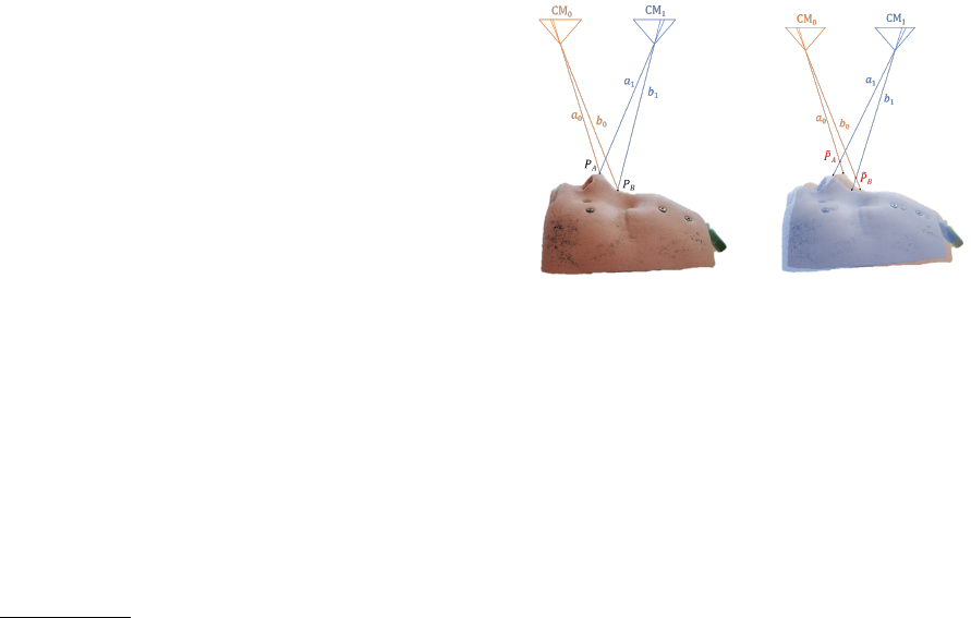
(a) No motion (b) Motion, but no compen-
sation
Figure 2: Graphical illustration of “no motion” and “mo-
tion” in-between image acquisitions, without any motion
compensation.
Visually, we demonstrate the impact of motion in-
between image acquisitions with help of Figure 2. For
ease of illustration, head side-view is used and refer-
ence mapper frame (which is fixed as in Figure 1) is
not shown. In Figure 2 (a) the 3D face points P
A
and
P
B
are imaged from first camera location CM
0
and
second camera location CM
1
. In this case, there is no
motion in-between the image acquisitions and rays a
0
,
a
1
for camera CM
0
, CM
1
, respectively, reconstruct
point P
A
correctly; similarly rays b
0
, b
1
reconstruct
point P
B
. If there is some motion in between the im-
age acquisitions, the face would have been moved to
a new position (shown in blue shade in Figure 2 (b)).
Because of this motion, the two points would appear
at relatively same but different positions. Rays from
the two cameras would then intersect at points
˜
P
A
and
˜
P
B
significantly above the actual facial surface.
We implemented two methods to eliminate this
motion effect. The first one considers the cameras
to have their veridical positions and corrects for mo-
tion by shifting facial image points to image coordi-
nates they would have had, if no motion had occurred.
We call the method “disparity correction”. The sec-
ond method corrects for motion by computationally
“moving” the cameras to positions and orientations
from where they would have acquired the images they
really acquired, however, if the head had not moved.
3.1 Object Motion Compensation by
Disparity Correction
In this method, the disparity change an image point
experiences due to the head’s motion is to be esti-
mated. This requires the 3D positions of the object
points w.r.t. the cameras’ poses to be known. Gen-
erally, object points can easily be determined by ray
intersection (“triangulation”). However, as long as the
object motion is not considered, point triangulation by
ray intersection of homologous image points can only
be approximately correct. Once such approximate 3D
co-ordinates are computed, the motion’s effect on im-
age co-ordinates can be predicted and corrected for -
provided it is known.
As mentioned previously, in our setup object mo-
tion is measured with an electromagnetic localizer
mounted on the facial surface. As markers on the
surface of the mapper frame provide a reference co-
ordinate system in which camera orientations can be
computed, and as the mapper frame carries an elec-
tromagnetic localizer, the motion of the triangulated
object point can be calculated in camera coordinates.
Re-projection to the image provides motion-corrected
image co-ordinates. Using the corrected image co-
ordinate pair, 3D object space co-ordinates can be
recomputed with higher accuracy. Within few iter-
ations, image co-ordinate pairs, disparities and 3D
space co-ordinates free from motion effects can be ob-
tained.
In the preparatory computational steps
2
, exterior
orientations of the images are computed by e.g. spa-
2
These steps are also necessary when patient co-
registration is done without compensating inter-image pa-
tient motion.
tial resection using the markers on the mapper frame.
Using the mapper frame localizer data, image orienta-
tions are computed in co-ordinates of the electromag-
netic navigation system. Therefore, the motion effect
on preliminary triangulated 3D co-ordinates can be
computed from:
˜
X = H · X (1)
where X is the (approximate) 3D space point before,
˜
X is the 3D space point after the motion, and H is the
homography describing the motion effect as:
H = H
i
· H
−1
0
(2)
where H
i
corresponds to the position of head at the
time of i
th
image acquisition, with i = 0 being the in-
dex of the reference homography. Then the approx-
imate 3D space point
˜
X is re-projected to the image.
The difference of the re-projected and actual image
points provides the motion disparity, which is then
subtracted from the points image co-ordinates provid-
ing motion-compensated image co-ordinates. This is
used for the next iteration’s triangulation. Empirically
it was observed that no more than four iterations of
this procedure are necessary until convergence.
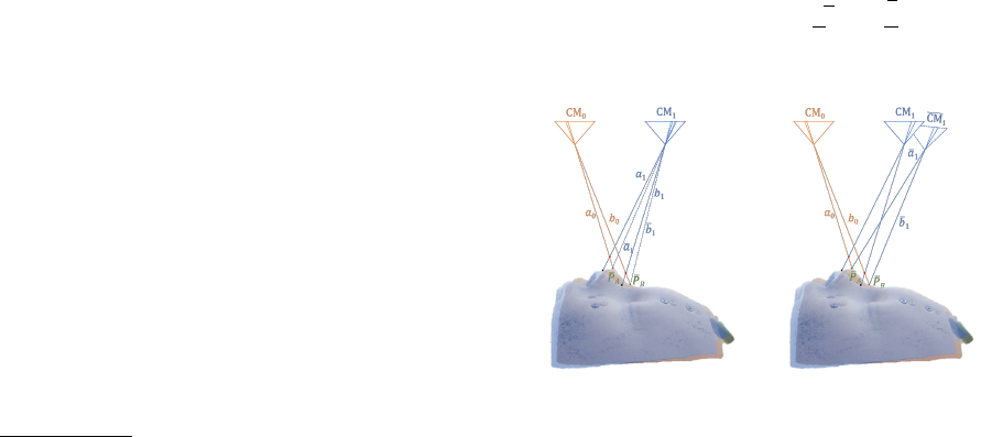
Unless the motion occurring in-between acqui-
sitions is compensated, two pairs of rays (a
0
, b
0
)
and (a
1
, b
1
) shown in Fig. 2 (b) would result in
wrongly reconstructed 3D points
˜
P
A
and
˜
P
B
, respec-
tively. Fig. 3 (a) shows the graphical illustration of
the motion compensation with disparity shift. From
the intersection of rays a
0
and a
1
(b
0
and b
1
), motion
disparity is computed and used to shift the image co-
ordinates to the corrected position, such that the rays
a
1
and b
1
are iteratively shifted to a
1
and b
1
, produc-
ing correct reconstructed points P
A
and P
B
, respec-
tively.
(a) Motion compensation
by disparity correction
(b) Motion compensation
by moving cameras
Figure 3: Motion compensation using the two proposed
methods.
3.2 Object Motion Compensation by
Moving Cameras
According to the moving cameras approach the cam-
eras are “imagined” to be fixed to the patient’s facial
surface, while they are not really so. Therefore, the
exterior orientations of the images have to be changed
in order to compensate for the actual motion of the
facial surface. This is formulated for each camera’s
projection center C
i
and rotation matrices R
i
as
˜
C
i
= H
i
· C
i
(3)
˜
R
i
= R
i
· R
H
−1
i
(4)
where
˜
C
i
and
˜
R
i
corresponds to the shifted projection
center and rotation matrix, respectively, after com-
pensating for the motion of the i
th
image acquisition
w.r.t. the reference acquisition. R
H
i
corresponds to
the rotational component of H
i
. With the new exte-
rior orientations
˜
C
i
and
˜
R
i
, the correct facial points
are triangulated.
Finally, the inverse of the motion adaptation ap-
plied to the reference camera needs to be applied to
the triangulated points by transforming them using the
electromagnetic reference homography H
−1
0
.
V = H
−1
0
·
˜
V (5)
where
˜
V is a 3D point in the co-ordinate system of
the moved cameras and V is the same point in co-
ordinates defined by the mapper frame.
Fig. 3 explains moving camera motion compensa-
tion graphically. Relative to reference camera CM
0
,
the camera position CM
1
in Fig. 3 (b) is shifted to
CM
1
. Rays a
1
and b
1
from this corrected camera posi-
tion intersect with their corresponding rays a
0
and b
0
to produce corrected points P
A
and P
B
, respectively.
3.3 Impact of Uncompensated Motion
When the two algorithms are applied to real data they
produce significantly differing results. This is due
to the fact that electromagnetic motion measurements
are - like any measurements - subject to noise, and
that individual noise components in a measurement
could have large effect on results. This we want to ex-
plain and graphically demonstrate in this subsection.
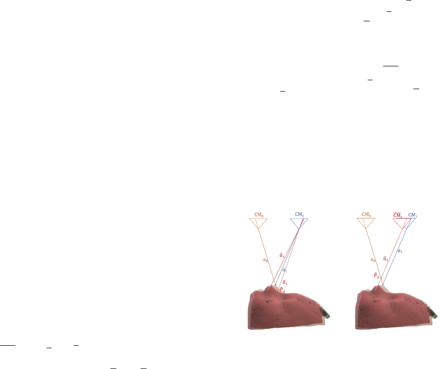
Fig. 4 shows a case where no motion occurs, but
the electromagnetic sensors - due to noise effects -
“pretend” that some motion is present. Rays a
0
and
a
1
cause image points in the CM
0
and CM
1
cam-
eras, respectively. In case of the disparity shift ap-
proach (Fig. 4 (a)), the erroneous motion measure-
ment wrongly informs that ray a
1
in CM
1
is com-
ing from direction ˆa
1
which is where the visible point
should be (shown in red shade), if the motion had oc-
curred. Disparity correction adds the viewing differ-
ence between ˆa
1
and a
1
, not to ˆa
1
, but to the visible
point generated by ray a
1
such that direction a
1
is gen-
erated. Triangulation with rays a
0
and a
1
then results
in a wrongly reconstructed point P
A
far below the ac-
tual face surface.
In case of moving cameras approach (Fig. 4 (b)),
the erroneous motion measurement transforms the
camera CM
1
to the wrong position CM
1
such that
the original ray a
1
is at position a
1
. Intersection of
rays a
0
and a
1
lead to the reconstructed point P
A
well
above the patient surface. So while moving camera
generates the point above the actual surface, the dis-
parity correction generates the same point more deep
into the actual surface. As there is noise in any (elec-
tromagnetic) measurement, this effect occurs also in
presence of an actual facial motion - which is why on
the same data both compensation methods give com-
pensation results that do not precisely agree with each
other while functioning correctly.
(a) no motion but compen-
sation by disparity shift
(b) no motion but compen-
sation by moving cameras
Figure 4: Motion compensation for noisy motion measure-
ment.
4 EXPERIMENTS AND
EVALUATIONS
In this section, we evaluate the two discussed motion
compensation algorithms. Any motion in-between the
three image acquisitions has a direct influence on the
reconstructed facial surface, which is then used for the
photogrammetric co-registration. A poor reconstruc-
tion without any motion compensation would affect
the photogrammetric co-registration. We try to quan-
tize this influence based on the difference between a
reference transformation and a photogrammetrically
obtained transformation.
A reference co-registration was carefully obtained
with non-photogrammetric tactile (i.e. touch-based)
measurements for real patient. For phantom face the
reference could also be obtained by photogrammetry
without moving the phantom in between image acqui-
sitions. This reference transform is termed as H
R
. Its
quality can be visually verified by an expert as suffi-
ciently good based on electromagnetic pointer super-
imposition displayed on screen. This reference trans-
form remains stable as long as the position of patient
localizer on the patient’s face remains fixed. Any pho-
togrammetric co-registration transform H
N
obtained
for the same mounting of patient localizer has to be
equal to the reference transform H
R
.
The transformation difference δH = H
R
× H
−1
N
is not an easily interpretable numeric measure. For
instance, if the units in which coordinates are ex-
pressed is changed from mm to cm the weighting
of rotation differences versus translation differences
changes resulting in meaningless changes of the mea-
sure (i.e. the numbers in the transformation matrix).
Therefore, a volume grid of n
3
points in the region of
3D space where the facial surface is approximately lo-
cated is evaluated instead. This volume grid is trans-
formed by δH, to obtain a new volume grid. Vectors
are calculated as difference of new grid positions to
the reference grid positions. The average length of
these vectors is used as divergence measure for com-
parison. Lower divergence measure would mean that
the photogrammetric transform H
N
is closer to refer-
ence transform H
R
.
4.1 Phantom Face
The first set of experiments was performed for a
phantom face, with supervised motion in-between the
three images. In these experiments, controlled mo-
tion was also verified with the head-mounted electro-
magnetic sensor’s response. A non-metallic six de-
gree of freedom stage was designed, mainly consist-
ing of wood and plastic in order to avoid metal in-
fluencing the electromagnetic field of the navigation
system. The bottom of the wooden box was equipped
with a fixed plastic glass allowing a second plastic
glass holding the phantom to slide smoothly on verti-
cal plastic screws located close to its corners. The ver-
tical screws allowed translation in z direction and ro-
tations around x and y axes. The sliding plastic glass
was held by four pairs of horizontal screws (one for
each side) allowing translations in x and y and rota-
tions around the z axis. The mapper frame was inde-
pendently fixed on a tripod stand.
First a reference registration was performed with-
out motion in-between image acquisitions, thereby
obtaining H
R
. Without disturbing the patient local-
izer, systematic motions were applied on the phantom
face between the three image acquisitions. Experi-
ments were conducted to include independent trans-
lations in the three directions and rotations around the
three axes. These motions were verified with the elec-
tromagnetic patient localizer and variations were ob-
served to be in permissible limits. Table 1 shows the
type and extent of motion applied for various cases
of this experiment. The same motion was applied in-
between the first and second as well as in-between
second and third image acquisition.
For this experiment, photogrammetrically ob-
tained no-motion reference facial surface was com-
pared against the photogrammetric surface of indi-
vidual motion-compensation cases. Distance between
the two surfaces encoded with color is included in Ta-
ble 1 for different compensation schemes. The diver-
gence measure with and without motion compensa-
tion was calculated for a 3D grid with n = 6 (shown
below the colored surface plots). With the inclusion
of motion compensation in the facial surface recon-
struction, photogrammetric co-registration improves
significantly. Deviation as large as 7.5 mm are re-
duced to 1.3 mm.
Handheld Phantom
Figure 5: Image of a handheld phantom, which is involun-
tary subjected to small movements.
To further observe the effectivity of motion compen-
sation on real scenario, experiments were performed
with the phantom face unstably held by hand (c.f. Fig.
5). This would allow the natural hand vibrating mo-
tions to influence the phantom position in-between the
three image acquisitions. Table 2 shows three exper-
iments performed in this series. To quantify the mo-
tion in-between image acquisitions, translation in the
approximate nose position is measured. Case 3 in Ta-
ble 2 shows that even for small motions, without any
motion compensation the divergence could be very
large. This large divergence is reduced to within 2
mm by proposed methods. A more comprehensive
record of the actual motion of the phantom’s facial
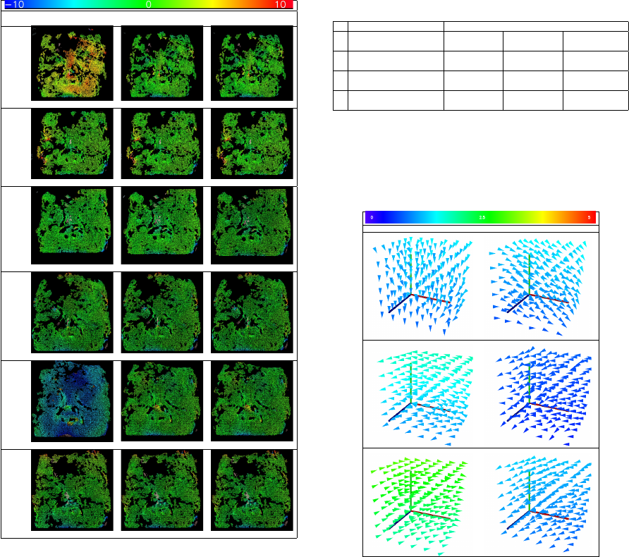
Table 1: Deviations remaining after different compensation
algorithms for controlled motion of phantom in-between the
three images. Distance encoded colored surface shows the
registration quality of the individual case followed by diver-
gence measure. Color scale on the top is in mm.
Motion
No Motion
Compensation
Disparity Shift
Compensation
Moving Camera
Compensation
x shift: 0.7mm
5.488 1.056 1.055
y shift: 0.7mm
1.891 1.241 1.231
z shift: 0.7mm
0.534 0.327 0.345
x rotation: 0.32
◦
1.149 0.947 0.943
y rotation: 0.48
◦
7.564 1.392 1.389
z rotation: 0.32
◦
2.907 1.098 1.103
surface is shown in Table 3. These plots show the
facial motion via grid points (approximately located
around the facial surface) in between the image ac-
quisitions. So the graph visualizes the motion that is
to be compensated by the motion compensation ap-
proach.
4.2 Real Patient
Finally, evaluations were performed on real patients
where the reference registration H
R
was obtained
by touch-based tactile registration. This touch-
based reference registration is compared against the
photogrammetry-based registration H
N
. Table 4 lists
the deviation of the compensation algorithms, when
Table 2: Deviations remaining after applying different com-
pensation algorithms for handheld phantom. Motion in-
between image acquisition as measured by an approximate
point near the patient’s nose. Two motions for each case
denote the translation in the nose in-between images 1 and
2 as well as images 2 and 3.
Motion Deviation [mm]
Translation [mm] No Motion
Compensation
Disparity Shift
Compensation
Moving Camera
Compensationx y z
1
0.046 0.798 -0.354
3.828 2.148 2.145
-0.165 0.073 -0.076
2
0.214 0.645 -0.268
4.165 1.535 1.543
0.234 0.423 -0.282
3
-0.657 -1.129 0.656
54.668 1.970 1.987
0.336 0.852 -0.349
Table 3: In-between images motion shown as deviation of
grid points approximated around patient’s head for hand-
held phantom experiments of Table 2. The color bar on top
shows the color coding (in mm) used as distance measure of
these vectors.
Difference between image 1 and image 2 Difference between image 2 and image 3
used on real patients for three cases. A large devia-
tion of 20 mm is compensated to surgical precision of
within 3 mm. Motion in-between images as measured
by an approximate point near the patients nose is also
specified. Table 5 shows deviation of grid points (ap-
proximated around the patients head) in-between the
image acquisitions.
5 CONCLUSION
With the advancement in photogrammetry, its use
has been increasing in the medical fields. Image-
based surface reconstruction provides a non-invasive
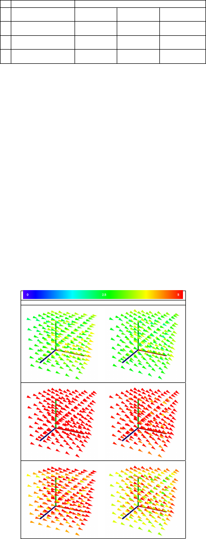
Table 4: Deviations remaining after different compensa-
tion algorithms for a real patient in three different cases.
Motion in-between images as measured by an approximate
point near the patient’s nose is specified as translations in-
between images 1 and 2 as well as images 2 and 3.
Motion Deviation [mm]
Translation [mm] No Motion
Compensation
Disparity Shift
Compensation
Moving Camera
Compensationx y z
1
-3.846 0.852 0.313
8.965 3.103 2.981
-3.320 1.892 0.948
2
-8.235 4.537 2.942
20.191 1.686 1.774
-5.637 3.689 2.311
3
-5.886 1.223 0.964
15.853 2.841 2.845
-4.434 2.483 1.538
alternative for various medical applications. How-
ever, while surgical precision is required, VSfM pho-
togrammetry can be affected even by small motions
in between acquisitions of monocular images. In this
work, we remedy the effect of motion in-between im-
age acquisitions by compensating the measured mo-
tion. We introduced disparity correction and moving
camera methods as the two techniques to compen-
sate the motion in-between image acquisitions. Our
experiments on phantom face and real patient show
the robustness of the proposed techniques. Both pro-
posed methods give similar results, moving cameras
approach being preferred because of its non-iterative
solution.
Table 5: In-between images motion shown as deviation of
grid points for real patient data of Table 4. The color bar
shows the color coding (in mm) used as distance measure of
these vectors.
Difference between image 1 and image 2 Difference between image 2 and image 3
REFERENCES
Barbero-Garc
´
ıa, I., Lerma, J. L., Miranda, P., and Marqu
´
es-
Mateu,
´
A. (2019). Smartphone-based Photogrammetric
3D Modelling Assessment by Comparison with Radio-
logical Medical Imaging for Cranial Deformation Anal-
ysis. Measurement: Journal of the International Mea-
surement Confederation, 131:372–379.
Clausner, T., Dalal, S. S., and Crespo-Garc
´
ıa, M. (2017).
Photogrammetry-based Head Digitization for Rapid and
Accurate Localization of EEG Electrodes and MEG
Fiducial Markers Using a Single Digital SLR Camera.
Frontiers in Neuroscience, 11:264.
Ey-Chmielewska, H., Chru
´
sciel-Nogalska, M., and
Fra¸czak, B. (2015). Photogrammetry and its Potential
Application in Medical Science on the Basis of Selected
Literature. Advances in clinical and experimental
medicine : official organ Wroclaw Medical University,
24(4):737–741.
Fitzgibbon, A. W. and Zisserman, A. (2000). Multibody
Structure and Motion: 3D Reconstruction of Indepen-
dently Moving Objects. In European Conference on
Computer Vision, pages 891–906. Springer.
Furukawa, Y. and Ponce, J. (2009). Accurate, Dense,
and Robust Multiview Stereopsis. IEEE transactions on
pattern analysis and machine intelligence, 32(8):1362–
1376.
Grimson, W. E. L. (1981). From Images to Surfaces: A
Computational Study of the Human Early Visual System.
MIT press.
Hartley, R. and Zisserman, A. (2003). Multiple View Geom-
etry in Computer Vision. Cambridge university press.
Hellwich, O., Rose, A., Bien, T., Malolepszy, C., Muchac,
D., and Kruger, T. (2016). Patient Registration using
Photogrammetric Surface Reconstruction from Smart-
phone Imagery. International Archives of the Pho-
togrammetry, Remote Sensing and Spatial Information
Sciences - ISPRS Archives, 41(July):829–833.
Newcombe, R. A., Fox, D., and Seitz, S. M. (2015). Dy-
namicfusion: Reconstruction and Tracking of Non-Rigid
Scenes in Real-Time. In Proceedings of the IEEE confer-
ence on computer vision and pattern recognition, pages
343–352.
Ozden, K. E., Schindler, K., and Van Gool, L. (2010).
Multibody Structure-from-Motion in Practice. IEEE
Transactions on Pattern Analysis and Machine Intelli-
gence, 32(6):1134–1141.
Salazar-Gamarra, R., Seelaus, R., Da Silva, J. V. L., Da
Silva, A. M., and Dib, L. L. (2016). Monoscopic Pho-
togrammetry to obtain 3D Models by a Mobile Device:
A Method for Making Facial Prostheses. Journal of Oto-
laryngology - Head and Neck Surgery, 45(1):1–13.
Tola, E., Knorr, S., Imre, E., Alatan, A. A., and Sikora, T.
(2005). Structure from Motion in Dynamic Scenes with
Multiple Motions. In Workshop On Immersive Commu-
nication and Broadcast Systems.
Ullman, S. (1979). The Interpretation of Structure from
Motion. Proceedings of the Royal Society of London,
203(1153):405–426.
