
A Methodological Assistant for Use Case Diagrams
Erika Rizzo Aquino
1,2 a
, Pierre de Saqui-Sannes
1 b
and Rob A. Vingerhoeds
1 c
1
ISAE-SUPAERO, Universit
´
e de Toulouse, France
2
ITA, S
˜
ao Jos
´
e dos Campos, Brazil
Keywords:
Use Case Diagram, Methodology, SysML, UML.
Abstract:
Use case driven analysis is the corner stone of software and systems modeling in UML and SysML, respec-
tively. Although many books and tutorials have discussed the use of use case diagrams, students and industry
practitioners regularly face methodological problems in writing good use cases. This paper defines a method-
ological assistant that helps designing use case diagrams relying on formalized rules and reuse of previous
diagrams. The methodological assistant is implemented in Python. It is interfaced with the free SysML soft-
ware TTool, and with Cameo Systems Modeler.
1 INTRODUCTION
Adoption of Model-Based Systems Engineering ap-
proaches is a challenging issue for systems and soft-
ware manufacturers. Implementing a MBSE ap-
proach requires working on a triptych (language,
tools, method). Ranging from formal methods to dia-
grammatic notations such as UML (OMG, 2018) and
SysML (OMG, 2017), many papers have discussed
model simulators, formal verification tools, and code
generators. By contrast, little work has been pub-
lished on tools that may assist UML and SysML dia-
grams designers in implementing a method.
This paper discusses the use of UML and SysML
use case diagrams, and good ways of developing them
using a methodological assistant. Two complemen-
tary avenues are explored. First, the assistant can help
constructing use case diagrams relying on formalized
rules and repositories of previously designed use case
diagrams. Second, the assistant can check use case
diagrams a posteriori.
The paper is organized as follows. Section 2 iden-
tifies difficulties in writing good use case diagrams.
Section 3 discusses the design and implementation
of UCcheck, a methodological assistant that is coded
in Python and interfaced with TTool (TTool, 2019)
and Cameo Systems Modeler (Casse, 2018). Section
4 discusses a case study. Section 5 surveys related
a
https://orcid.org/0000-0002-1840-691X
b
https://orcid.org/0000-0002-1404-0148
c
https://orcid.org/0000-0002-2339-4853
work. Section 6 concludes the paper and outlines fu-
ture work.
2 GUIDELINES FOR DRAWING
USE CASE DIAGRAMS
2.1 Use Case diagrams
A SysML (resp. UML) use case diagram identifies the
main functions and services to be offered by a system
(resp. a piece of software).
A rectangle defines the boundary of the system
or software, and names it (On Figure 1 the system
is named Real-Time System). The ovals depict the
use cases that contain the names of the functions
or services to be offered. On Figure 1, Perform
Computation is a use case.
A use case diagram defines relations between
pairs of use cases. On Figure 1, the extend relation
makes InformUsers and StoreResults an option of
PerformComputation. The include relation from
PerfomComputation to AcquireInputs states each
computation demands to acquire values from sensors.
A use case diagram also shows the system or soft-
ware interacts with its environment, the latter being
depicted by a set of actors. On Figure 1, a link con-
nects use case AcquireInputs to actor Sensors.
Aquino, E., de Saqui-Sannes, P. and Vingerhoeds, R.
A Methodological Assistant for Use Case Diagrams.
DOI: 10.5220/0008938002270236
In Proceedings of the 8th International Conference on Model-Driven Engineering and Software Development (MODELSWARD 2020), pages 227-236
ISBN: 978-989-758-400-8; ISSN: 2184-4348
Copyright
c
2022 by SCITEPRESS – Science and Technology Publications, Lda. All rights reserved
227
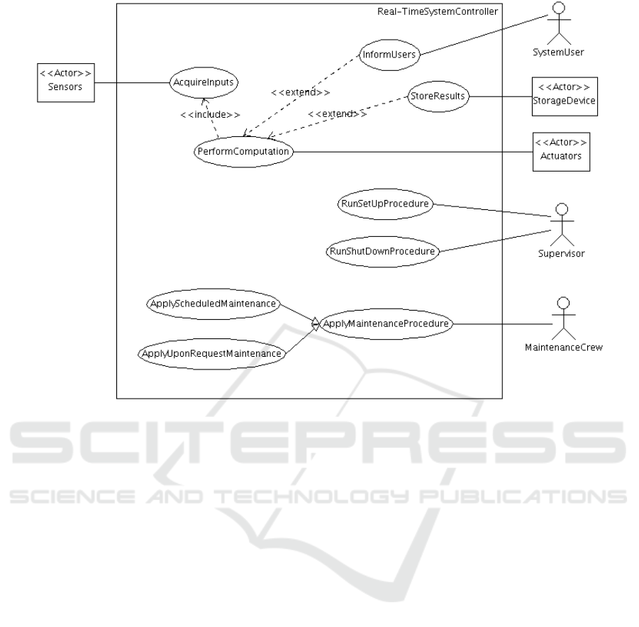
Figure 1: Use Case Diagram for real-time systems.
2.2 Generic Use Case Diagram
To create a generic use case diagram for a large vari-
ety of systems, one needs to keep in mind that:
• A system has a nominal behavior.
• A system may enter downgraded modes.
• A system must run a set up procedure before start-
ing its execution.
• A system must run a shutdown procedure be-
fore being moved or updated, and more generally
maintained and serviced.
• Maintenance is a normal concern when one is de-
signing a system.
Relying on previous principles, Figure 1 depicts a
generic use case diagram for a real-time system con-
troller that receives inputs from sensors and triggers
output devices, part of the latter being in charge of
informing the user and the supervisor of the system.
The use case diagram in Figure 1 depicts the set-
up, shutdown and maintenance phases that are usually
concealed by the use case diagrams presented in paper
or books addressing real-time systems modeling. One
may note that Figure 1 does not mention degraded
modes: they will be addressed in sequence or activ-
ity diagrams associated with the use case diagrams.
These documentation-purpose sequence and activity
diagrams are not presented in this paper. Discussion
is limited on use case diagrams for themselves.
2.3 Difficulties for Beginners
SysML textbooks and tutorials usually recommend a
four-step process to create a use case diagram: (1) de-
fine the boundary of the system; (2) identify the actors
as external entities that interact with the system; (3)
identify the use cases from the actors’ goals; (4) es-
tablish the connections between actors and use cases,
and set up relations between pairs of use cases. This
methodology is usually explained through an example
for a simple system (Weilkiens, 2011).
However, a major difficulty among beginners is to
maintain the use cases at the right level and to not
confuse between high-level functions and elementary
actions. The structure of the use case diagram induces
functional decomposition and consequent insertion of
low-level functions that do not generate value for the
actors (Holt and Perry, 2008).
With experience, the identification of use cases
becomes easier as the designer can rely on past mod-
els. Thus, one way to help beginners is to provide
various examples of use case diagrams. However,
the number of examples needed to cover multiple do-
MODELSWARD 2020 - 8th International Conference on Model-Driven Engineering and Software Development
228

mains may be very large. A better solution is to pro-
vide generic diagrams, which can be adapted to sim-
ilar systems. These diagrams can be designed by ex-
perts based on experience, and then be provided to be-
ginners to serve as guides. Consequently, an assistant
for use case diagrams should manage a repository of
example diagrams, helping to retrieve and customize
them.
Other common beginners’ errors have been inves-
tigated in the literature. The studies were conducted
with students and identified difficulties with choosing
the right type of relationship, defining the direction
of the extend relationship and proper naming of ele-
ments (Kruus et al., 2014a) (Chren et al., 2019a) (Holt
and Perry, 2008). For example, they reported the ab-
sence of verbs in use case names and the use of proper
names for actors rather than a common name repre-
senting a role. Consequently, an assistant for use case
diagrams should not only guide the identification of
actors and use cases, but also verify the diagram com-
pliance with SysML/UML and systems engineering
guidelines.
3 METHODOLOGICAL
ASSISTANT
3.1 Overview
In order to help designing use case diagrams, two
forms of assistance can be proposed: a priori assis-
tance, to facilitate the creation of a correct diagram
from scratch; and a posteriori assistance, to increase
quality and correctness of a semi-finished diagram.
The methodological assistant discussed in this paper
offers the two forms of assistance. The first version
of the tool merely verified whether a diagram is com-
pliant with SysML and Systems Engineering guide-
lines or not. This was insufficient to help beginners,
who find it difficult to select elements (actors and use
cases) at a good level of abstraction. The tool was en-
hanced to guide the creation of a new diagram from a
reference one. An additional module was developed
to store the reference use case diagrams in a database.
The methodological assistant is developed using
Python and the Tkinter library for user interfaces.
The rest of this section overviews the main modules of
the tool, the use of which will be illustrated in Section
4.
3.2 Verification Module
The Verification module receives a use case diagram
in XML format, identifies its elements and verifies
them against SysML rules and guidelines. The mod-
ule accepts XML files generated by two modeling
tools: TTool (TTool, 2019), a free software devel-
oped by Telecom Paris, and CAMEO Systems Mod-
eler (Casse, 2018), a tool developed by NoMagix,
now a subsidiary of Dassault Syst
`
emes.
A first step of the analysis consists of transform-
ing the XML file to a common object-oriented struc-
ture. In this structure, the diagram is a class that pos-
sess components and connectors. Components have
as attributes: name, type and position in the diagram.
Connectors, on the other hand, have name, position
and a reference to each one of two components being
linked. The objective of this pre-processing step is
to gain independence from the modelling tool. Then,
to extend the assistant to a new SysML/UML tool,
one need only to write a program that extracts the el-
ements and stores them in the class structure.
A set of rules, not listed here for space reasons,
has been established (Rizzo Aquino, 2019). Part of
these rules can be verified automatically. Others re-
quire user confirmation about the compliance with the
rules.
Two Python libraries were important for the veri-
fication module: wordnet to identify the grammatical
class of actors’ and use cases’ names, and networkx
to verify some relationship properties after transform-
ing the diagram into a graph.
3.3 Import Module
The Import module accepts a use case diagram in
XML format from TTool or CAMEO Systems Mod-
eler and stores it into a database.
A graphical interface asks the user whether the in-
serted file is a reference or an example one. A ref-
erence is defined as a general diagram for a group of
similar systems and can be used to guide the concep-
tion of new diagrams. An example is a diagram for
a specific system, which must be associated with the
name of a general category.
Using a database structure allows one to represent
the diagrams independently of the SysML tool. The
database model mimics the object-oriented structure
explained in 3.2. Moreover, a database stores a large
number of diagrams, and the execution of complex
queries.
3.4 Creation Module
The Creation module guides the user on the identifi-
cation of actors, use cases and relationships based on
a reference diagram chosen from the database. Then,
A Methodological Assistant for Use Case Diagrams
229

a graph is drawn to display elements and connections
identified in the diagram.
At each design step, the program suggests im-
provements. For example, if two actors are associated
with the same use cases, the program asks whether
they cannot be grouped into one common general ac-
tor.
4 CASE STUDY
4.1 A Priori Assistance
To demonstrate the functionalities and benefits of the
verification module, this section uses an agricultural
drone. The first version of the use case diagram (Fig-
ure 2) contains purpose-made errors that will be iden-
tified by the assistant.
According to the use case diagram, the system
possess two main functions: “control drone” and
“spread pesticides”. Actor Buyer is interested in the
two main functions. Actor Farmer is interested in
pesticide application. Actor operator is responsible
for controlling the drone. An actor named Customer
can be seen isolated in the diagram.
The interface of the verification assistant is di-
vided into tabs, each tab for one group of rules. (Fig-
ure 3) shows the tabs. The first one overviews the use
case diagram and the points to be verified. A check-
list helps clarifying the step-by-step verification pro-
cess and quickly localizing the mistake(s). Addition-
ally, the program helps the user to improve the level
of abstraction of the diagram. Having more than 20
(Balzert, 2006) use-cases may indicate the presence
of too low-level functions.
The next two tabs are focused on actors and use
cases. The program automatically verifies rules such
as “Names must start with a capital letter, be unique
and belong to correct grammar class.” The actors
should be named by common nouns. Use cases
should start with a verb. Also, the program looks for
use cases and actors that remain isolated.
The semantic compliance checks whether the ac-
tors and the use-cases respectively represent external
roles and high-level functions that produce an observ-
able result to an actor.
Note that verifying string equality is not sufficient
to assure uniqueness of actor’s names. Therefore, the
Leacock-Chodorow similarity function of Python’s li-
brary wordnet is used to certify that all names are se-
mantically different.
For our case study, it was possible to identify syn-
tactical errors. For instance, actor operator does not
start with a capital letter. Further, actor Adjustment
in strong wind must be rephrased with the verb
Adjust. The program also pointed out that the ac-
tor Customer is isolated in the diagram. Through the
semantic analysis mentioned above, a high correlation
is identified between the names Customer and Buyer.
Thus, one could hypothesize that the user changed the
name of actor from Customer to Buyer but forgot to
delete the old one. In this case, the correction will be
to remove the isolated actor from the diagram. How-
ever, in other situations, the problem may be a rela-
tionship that is missing.
Besides, through answering the questions, the
user noticed some incorrect use cases: Control
valves was too low-level and could be removed, and
Control drone was in the point of view of the user
and should be rewritten as the real function performed
by the drone, which is “Change direction by remote
control”. An extract of the actors check tab is pro-
vided by Figure 3. The use cases check tab follows
the same structure.
Then, the assistant checks the correctness of the
relationships between elements of the use case dia-
gram. Similarly, it is possible to automatically verify
some basic properties, such as no double linkage be-
tween the same pair of elements, no cycles, and cor-
rect type of elements for each type of relationship (for
example, an association can only be defined between
one actors and one use case). These checks guarantee
no relationship was left unintentionally.
For our case study, it was identified the incorrect
use of an association to link two use cases. This re-
lation needs to be changed to either an “include’, an
“extend” or a “generalization” relation - the only pos-
sibilities between use cases. The correction applied
by the user is to change the association to a include
relationship. Further verification of relationships is
only possible if all the above properties are respected.
The user has to apply the corrections mentioned un-
til then and resubmit an intermediate version of the
diagram.
The correctness of the basic properties allows the
user to verify whether the type of relationships be-
tween use cases agrees with the desired meaning.
Asking the user if it is a necessary, an optional or a
specialization relation accomplishes this. These ideas
should correspond to the “include”, “extend” and
“generalization” relationship, respectively. A warn-
ing message is exhibited in case of mismatch. The
user is also asked if the relation is in the correct direc-
tion or not. Only with the use case diagram, it is not
possible to verify automatically if relationships are
consistent with their meaning. Therefore, the check is
user dependent. The advantage of the designed inter-
face is that it does not directly use the SysML/UML
MODELSWARD 2020 - 8th International Conference on Model-Driven Engineering and Software Development
230
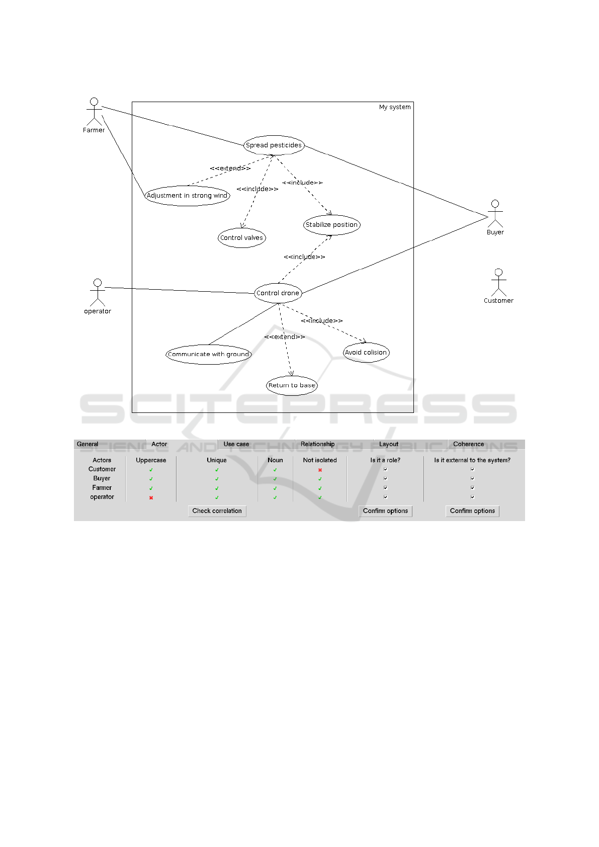
Figure 2: Initial use case diagram for an agricultural drone.
Figure 3: Extract of Actor Tab for verifying the name and meaning of the actors.
nomenclature, which poses problems for beginners.
Instead, it uses to idea behind the relationship type,
which is less prone to confusion and helps to rein-
force nomenclature learning. The interface designed
to verify the points mentioned above is portrayed in
Figure 4.
For the diagram in Figure 2, the user of the
methodological assistant identified two reverse rela-
tions, and one incorrect meaning. He noticed that
the use case Return to base should be rewritten to
represent an action performed only in case of bad
weather conditions. With the right set of questions,
the assistant reinforces inspection on commonly mis-
understood points.
Furthermore, the tool contributes for a cleaner di-
agram by identifying unnecessary relations. For ex-
ample, an actor associated to a use case does not need
to be associated to its refined use cases, since there
is already an implicit communication. Similarly, a
specialized actor implicit communicates with the use
cases linked to the generalized actor. No unnecessary
relationship was found in our case study.
Finally, by analyzing relationships, the assistant
can identify those actors and use cases that are possi-
bly of too high-level, in the case they are connected
to all elements. It can also identify actors that may
represent the same role in the case they are associated
to the same set of use cases.
The assistant identifies that actor Buyer is a too
high-level one. This means that either the diagram
A Methodological Assistant for Use Case Diagrams
231

Figure 4: Extract of Relationships Tab for verifying connection properties.
conveys the point of view of Buyer and the latter does
not need to appear, or that Buyer represents multi-
ple roles and should be decomposed, or that some use
case is missing. For the case study, a decomposition
of actor Buyer leads to actors that are either similar to
Farmer or to Operator, in the sense that they would
be connected to the same set of use cases. Thus, the
user finds out that actor Buyer actually combines the
two roles already in the diagram and can be taken out
of it. In other words, one can say that the diagram is
represented from the buyer’s point of view.
The two remaining tabs are focused on points not
directly related to actors, use cases and relationships.
The layout tab checks for the presence of a border.
It also verifies whether the actors were positioned
according to the categorization into primary actors
whose goal is fulfilled by the system, and secondary
actors who support the system. Although the clas-
sification into primary or secondary actors is not a
language standard, it is a common guideline among
SysML/UML community that should be followed for
interpretation purposes.
The coherence tab certifies that each use case is
documented by at least one scenario. This is accom-
plished by asking the user to match the use case to
the corresponding documentation, which can be a tex-
tual description, a sequence diagram or an activity di-
agram. Additionally, the matching must be coherent
with the relations between pairs of use cases. For ex-
ample, an included use case should appear in all the
scenarios of the including use case, because there is
a necessary relation between the two. On the other
hand, an extended use case should only appear in
some specific scenarios. Together, these checks rein-
force the completeness of the model and the meaning
of the relationships between use cases.
In summary, the case study demonstrated the as-
sistant’s ability to improve the diagram. The syntac-
tical errors were corrected, and the unnecessary re-
lationships were eliminated. The meanings of the
actors, use case and relationships were reinforced
through the questions answered by the user of the
tool. The two patterns (one element related to all
the others, and actors associated to the same use
cases) contributed to identify possible missing ele-
ments. Finally, the coherence matching helped to
check whether each use case was documented in a
scenario expressed by a sequence diagram.
However, one limitation of the verification mod-
ule is the dependence on user’s inputs, which may be
incorrect. Further work should explore how to auto-
mate the user dependent check. One idea would be to
use information from other diagrams of the model of
the system. For example, the context diagram could
be used to verify whether an actor is an external entity
to the system, or not. The sequence diagram together
with scenario matching could be used to verify the as-
sociation between actors and user cases.
4.2 A Posteriori Assistance
The functionalities of the creation assistant and its
potential benefits for beginners will be demonstrated
through a case study for a mobile phone camera. This
system belongs to the group of real-time systems,
whose generic use case diagram is presented in Sec-
tion 2.2.
The first step in the creation module consists of
filling up basic information about the model (author,
date and system’s name) and selecting the use case
diagram to use as reference. The process requires
the reference diagram to be previously inserted into
the database. In order to guide the user, the interface
presents the name of all example systems stored in the
database that are associated with the generic group.
Th user then proceeds to actor identification us-
ing the interface presented in Figure 5. A list of
suggestions is given based on the reference diagram.
For each suggested actor, the user can identify one
or more actors of the specific system being modeled.
For example, for a cellphone camera, the touch screen
corresponds to the sensor that receives capture or-
der and triggers the “Take photograph” functional-
ity. This function is executed by the cellphone camera
MODELSWARD 2020 - 8th International Conference on Model-Driven Engineering and Software Development
232

module itself, which corresponds to the actuator. The
given name must start with a capital letter, be unique
and contain a common noun.
For our case study, we identified two possible stor-
age devices: the cellphone internal memory and an
external memory. The system user plays the role of
taking and visualizing the photo and will be called
Photographer. The supervisor performs the role
of starting and closing the application and will be
identified as the Cellphone Owner. Often, these ac-
tors correspond to the same person in the physical
world. Additionally, no maintenance actor was se-
lected, since the part of the system being conceived
will not comprise maintenance functions.
Having a list of suggestions from a reference di-
agram facilitates actor identification, by transforming
it to an analogy exercise, and helps to keep the dia-
gram in an adequate level of abstraction. By combin-
ing a verification procedure, the assistant guarantees
the syntactic correctness of actors’ names.
Then, the user proceeds to use case identification.
The process is similar to that used for actors, ex-
cept that each suggestion only derives one use case.
For each suggested use case, the user must choose
whether or not to add it to the diagram, and by what
name. The name must start with capital letter, be
unique and start with a verb.
The suggestion list is optimized based on the ac-
tors selected. Only use cases that communicate to at
least one selected actor are suggested to the user. In
our case study, since no maintenance actor was cho-
sen, the use cases related to maintenance will not be
suggested to the user.
Finally, the user must establish the connections
between the chosen elements. Three tables are de-
picted in the interface: the first one for relations be-
tween actors, the second one for relations between use
cases, and the third one for associations between ac-
tors and use cases.
These tables are automatically semi-filled based
on the reference diagram. The user must input addi-
tional relations and make necessary changes. For ex-
ample, functions that are optional for some real-time
systems may be systematically executed in particular
ones. Then, the user has to manually change from
“extend” to “include” relationship. For a cellphone
camera, the use case Show image for the photogra-
pher when taking a photo will always happen, even if
for other types of camera it may be optional.
The advantage of the assistant is to combine orien-
tation from the pattern with a verification procedure.
For each new relationship, a series of functions pre-
vent the appearance of cycles, multiple inheritance
and unnecessary relationships, as explained in Sec-
tion 4.1.
The use case diagram created is displayed in a
graph format, where blue nodes represent actors, red
nodes represent use cases, and relationships are given
by edges. A list of warnings may be presented to indi-
cate the presence of isolated elements, too-high level
elements, that is, connected to all the others, or actors
that could represent the same role. Figure 6 exhibits
the use case diagram representation generated by the
assistant for the case study.
The benefits provided by the creation assistance
are an easier process of actors and use cases identifi-
cation, since it is replaced by an analogical reasoning
based on a reference diagram; and a final model more
in accordance with UML/SysML rules, as verification
procedures are automatically performed when possi-
ble.
One drawback of the implemented procedure lies
in the necessity to work with a generic diagram,
which introduces some dependence on the work of
an expert who created the generic diagram. How to
obtain generic diagrams automatically from a series
of example diagrams for a group of systems is still an
open issue.
At the moment, it is not possible to export the
graph representation of the use case diagram to a
modelling tool because of the positioning problem.
An automatic positioning function was used to ob-
tain the most readable graph. However, the arrange-
ment made does not comply with SysML/UML stan-
dards. The automatic layout of use case diagrams is a
complex problem addressed by some studies (Eichel-
berger, 2008).
5 RELATED WORK
5.1 Verifying Use Case Diagrams
Several studies have been conducted on verification of
UML/SysML diagrams. Unfortunately, research has
tended to focus on analysis of scenarios rather than of
use case diagrams. Scenarios can be either modeled
by sequence or activity diagrams, or documented by
a textual explanation of the use case. Analysis tech-
niques include graph transformation (Zhao and Duan,
2009) (Klimek and Szwed, 2010), logical verification
(Klimek and Szwed, 2010) and grammar formaliza-
tion (Chanda et al., 2009) (Christiansen et al., 2007).
In (Zhao and Duan, 2009) and (Klimek and
Szwed, 2010), the authors focused on verifying the
correctness and completeness of a scenario, but they
did not address a syntactical verification of UML stan-
dards. On the other hand, Chanda (Chanda et al.,
A Methodological Assistant for Use Case Diagrams
233
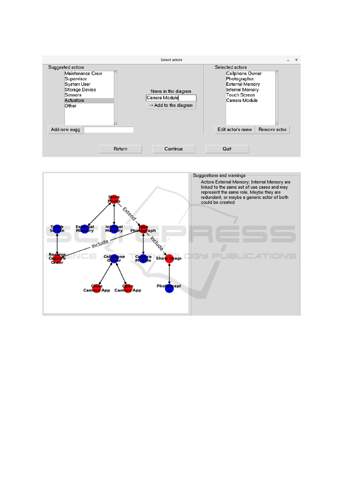
Figure 5: Selecting actors relying on a generic diagram.
Figure 6: Graph representation of the use case diagram created through the assistance for the cellphone camera. Suggestions
for improvements and warnings of missing elements are displayed next to the graph.
2009) investigated the use of formalization to verify
syntactical rules, however no computational tool is
proposed. The study in (Christiansen et al., 2007)
complements the prior by proposing the use of natural
language techniques to transform a use case descrip-
tion in the formal model. Deep natural language anal-
ysis is not necessary for the proposed assistant, since
it works with use case diagrams, in which phrases are
simpler and follow a structure - for example, to iden-
tify the verb of a use case, extracting the first word of
the sentence should be enough.
Some modeling tools have incorporated basic
checks for use case diagrams. For example, verifica-
tion of double relationships and of repeated elements
is available in Cameo System Modeler. The assistant
discussed in this paper is different from Cameo by the
broader spectrum of points to be verified, and by the
dialogue with the user of the assistant, asking him or
her questions such as “Is this actor really an external
entity?”
MODELSWARD 2020 - 8th International Conference on Model-Driven Engineering and Software Development
234

5.2 Assistance for Use Case Diagram
Creation
Many attempts have been made on how to automate
the creation of use case diagrams. Certain studies
proposed its derivation from other textual documents
through natural language processing. The transforma-
tion process has been applied to requirement (Seresht
and Ormandjieva, 2008), use case descriptions (El-
Attar and Miller, 2008) and user stories (Elallaoui
et al., 2018). The drawback of these proposals is that
the quality of the use case diagram highly depends on
the quality of the textual documents. Additionally, in
a system engineering logic, these documents are sup-
posed to be conceived from the use case diagram, and
not the opposite.
Other studies proposed the reuse of previous dia-
grams using case base reasoning (CBR) (Srisura and
Daengdej, 2010) or ontology (Bonilla-Morales et al.,
2012) approaches. From an initial draft of a use case
diagram, it was possible to retrieve the most similar
diagram from a database. However, the authors did
not investigate how to use this approach to create dia-
grams for new systems.
Finally, some authors examined the problem of
UML design from the educational point of view.
The studies (Chren et al., 2019b) and (Kruus et al.,
2014b) had pointed out the common mistakes made
by students in SysML/UML courses. In (Ramollari
and Dranidis, 2007), Ramollari proposed an object-
oriented modelling tool suitable for students. The
tool, called StudentUML, includes design and veri-
fication of some UML diagrams, as the sequence and
class diagram. Particularly, the use case diagram is
not addressed. Verification is only available for di-
agrams drawn in the platform. With respect to cre-
ation, the assistant proposed in this article differs from
Ramollari’s tool by the guidance functionality that is
provided to beginners. Actually, StudentUML works
like other modelling tools, but it offers a simpler in-
terface and further verifications.
6 CONCLUSIONS
A MBSE approach relies on a triptych (language,
tool, method). In terms of language, this paper fo-
cuses on use case diagrams and more precisely on
the version of them supported by the OMG-based
languages UML and SysML. In terms of tool and
method, the authors of this paper make a 3-fold state-
ment: (1) use-case diagrams have been existing for
many years ; (2) their use is the cornerstone of the use
case driven analysis step of the methods associated
with UML and SysML, and (3) Nevertheless, many
people still have difficulties in writing good use cases.
Previous three statements provide the rationale be-
hind the design and prototyping of a methodological
assistant that help UML and SysML model design-
ers to create and review their use case diagrams. The
tool named UCcheck helps constructing use case dia-
grams relying on formalized rules and repositories of
previously designed use case diagrams. It also check
use case diagrams a posteriori and suggests improve-
ments.
UCcheck is a free software coded in Python.
UCcheck was first interfaced with TTool, the free soft-
ware from Telecom Paris that we used to draw the use
case diagrams in Figure 1 and Figure 2. TTool has fur-
ther been applied for teaching, enhancing the expres-
sion power of SysML (de Saqui-Sannes and Apvrille,
2016), and for tooling the first steps of the life cycle of
systems (de Saqui-Sannes et al., 2018) (Mattei et al.,
2017) (Daigmorte et al., 2019).
The use of UCcheck is not restricted to TTool.
Indeed, UCcheck stores use case diagrams using an
intermediate form that is not specific to one partic-
ular UML or SysML tool. An interface exists for
Cameo Systems Modeler, a commercial tool from
Dassault Systems. Similarly, UCcheck can be inter-
faced with other SysML tools such as Entreprise
Architect (SparkSystems, 2019) and Rhapsody
(IBM-Rhapsody, 2019).
Beyond its interfaces with SysML tools, UCcheck
can be extended in several directions. In terms of
language, the tool may evolve if SysML2 (Object-
Management-Group, 2017) modifies the syntax or se-
mantics of use case diagrams. In terms of assis-
tance technique, introduction of Case Base Reason-
ing (CBR) may contribute to reuse SysML models or
patterns to assist the designer of use case diagrams.
ACKNOWLEDGEMENTS
First author has received financial support from the
BRAFITEC program funded by CAPES. The authors
acknowledge the support of ARISE chair and Thales.
REFERENCES
Balzert, H. (2006). UML 2 compact (In French). Eyrolles.
Bonilla-Morales, B., Crespo, S., and Clunie, C. (2012).
Reuse of use cases diagrams: an approach based on
ontologies and semantic web technologies. IJCSI In-
ternational Journal of Computer Science Issues, 9(2).
Casse, O. (2018). SysML in Action with Cameo Systems
Modeler. ISTE Press, Elseiver.
A Methodological Assistant for Use Case Diagrams
235

Chanda, J., Kanjilal, A., Sengupta, S., and Bhattacharya,
S. (2009). Traceability of requirements and consis-
tency verification of uml use case, activity and class
diagram: A formal approach. In 2009 Proceeding of
International Conference on Methods and Models in
Computer Science (ICM2CS), pages 1–4. IEEE.
Chren, S., Buhnova, B., Macak, M., Daubner, L., and Rossi,
B. (2019a). Mistakes in uml diagrams: analysis of
student projects in a software engineering course. In
Proceedings of the 41st International Conference on
Software Engineering: Software Engineering Educa-
tion and Training, pages 100–109. IEEE Press.
Chren, S., Buhnova, B., Macak, M., Daubner, L., and Rossi,
B. (2019b). Mistakes in uml diagrams: analysis of
student projects in a software engineering course. In
Proceedings of the 41st International Conference on
Software Engineering: Software Engineering Educa-
tion and Training, pages 100–109. IEEE Press.
Christiansen, H., Have, C. T., and Tveitane, K. (2007).
From use cases to uml class diagrams using logic
grammars and constraints. In RANLP, volume 7,
pages 128–132.
Daigmorte, H., de Saqui-Sannes, P., and Vingerhoeds, R. A.
(2019). A sysml method with network dimensioning.
5th IEEE International Symposium on Systems Engi-
neering (ISSE 2019).
de Saqui-Sannes, P. and Apvrille, L. (2016). Making mod-
eling assumptions an explicit part of real-time systems
models. the 8th European Congress Embedded Real
Time software and systems (ERTS2)).
de Saqui-Sannes, P., Vingerhoeds, R. A., and Apvrille, L.
(2018). Early checking of sysml models applied to
protocols”. In 12th International Conference on Mod-
eling, Optimisation and Simulation (Mosim 2018),
Toulouse, France.
Eichelberger, H. (2008). Automatic layout of uml use case
diagrams. In Proceedings of the 4th ACM symposium
on Software visualization, pages 105–114. ACM.
El-Attar, M. and Miller, J. (2008). Producing robust use
case diagrams via reverse engineering of use case de-
scriptions. Software & Systems Modeling, 7(1):67–83.
Elallaoui, M., Nafil, K., and Touahni, R. (2018). Automatic
transformation of user stories into uml use case dia-
grams using nlp techniques. Procedia computer sci-
ence, 130:42–49.
Holt, J. and Perry, S. (2008). SysML for systems engineer-
ing, volume 7. IET.
IBM-Rhapsody (2019). https://www.ibm.com/ca-
en/marketplace/architect-for-systems-engineers.
Klimek, R. and Szwed, P. (2010). Formal analysis of use
case diagrams. Computer Science, 11:115–131.
Kruus, H., Robal, T., and Jervan, G. (2014a). Teach-
ing modeling in sysml/uml and problems encountered.
In 2014 25th EAEEIE Annual Conference (EAEEIE),
pages 33–36. IEEE.
Kruus, H., Robal, T., and Jervan, G. (2014b). Teach-
ing modeling in sysml/uml and problems encountered.
In 2014 25th EAEEIE Annual Conference (EAEEIE),
pages 33–36. IEEE.
Mattei, A.-P., Loures, L., de Saqui-Sannes, P., and Escudier,
B. (2017). Feasibility study of a multispectral cam-
era with automatic processing onboard a 27u satellite
using model based space system engineering. IEEE
Systems Conference (SysCon).
Object-Management-Group (2017). Systems modeling lan-
guage (sysml) v2 rfp.
OMG (2017). OMG Systems Modeling Lan-
guage. Object Management Group,
https://www.omg.org/spec/SysML/1.5.
OMG (2018). OMG Unified Modeling Language (OMG
UML) Version 2.5. Object Management Group,
https://www.omg.org/spec/UML/2.5/PDF.
Ramollari, E. and Dranidis, D. (2007). Studentuml: An ed-
ucational tool supporting object-oriented analysis and
design. In Proceedings of the 11th Panhellenic Con-
ference on Informatics, pages 363–373.
Rizzo Aquino, E. (2019). Guidelines and tools for uml and
sysml use case diagrams. Internal Report RT/2019/2 -
DISC Department - ISAE SUPAERO.
Seresht, S. M. and Ormandjieva, O. (2008). Automated
assistance for use cases elicitation from user require-
ments text. In Proceedings of the 11th Workshop on
Requirements Engineering (WER 2008), volume 16,
pages 128–139.
SparkSystems (2019). Entreprise-architect,
https://www.sparxsystems.com/products/ea/.
Srisura, B. and Daengdej, J. (2010). Retrieving use case
diagram with case-based reasoning approach. Journal
of Theoretical and Applied Information Technology,
19(2):68–78.
TTool (2019). An open-source uml and sysml toolkit,
https://ttool.telecom-paristech.fr.
Weilkiens, T. (2011). Systems engineering with
SysML/UML: modeling, analysis, design. Elsevier.
Zhao, J. and Duan, Z. (2009). Verification of use case with
petri nets in requirement analysis. In International
Conference on Computational Science and Its Appli-
cations, pages 29–42. Springer.
MODELSWARD 2020 - 8th International Conference on Model-Driven Engineering and Software Development
236
