
Generation of Tree Surface Mesh Models from Point Clouds using Skin
Surfaces
Chi Wan Lim
a
, Like Gobeawan
b
, Sum Thai Wong
c
, Daniel J. Wise
d
, Peng Cheng
e
,
Hee Joo Poh
f
and Yi Su
g
Institute of High Performance Computing, A*STAR, Singapore
Keywords:
Tree Modelling, Point-based Processing, Skin Surfaces.
Abstract:
This work focuses on the extraction and reconstruction of the tree branching models from large scale 3D
LiDAR point clouds, utilizing the concept of skin models for modelling tree joints. Tree joints are one of
the most challenging components to model due to its potential for highly intricate morphology and complex
branching topology. During the reconstruction process, point clouds first undergo a classification process to
remove leaves and then skeletonization to derive the branching morphology and estimate individual branch
thicknesses. The tree branching model can then be modelled as a collection of cylindrical volumes connected
by fused tree joints. The novelty of this work lies in the usage of skin surfaces as a proxy for modelling the
tree joints. The generated tree triangular mesh surface is smooth and continuous, and we further propose a
method to convert it into quadrilateral patches. The benefits of having piecewise components of branches and
joints are such that it facilitates the subsequent generation of 3D finite elements, as they can be handled and
meshed independently.
1 INTRODUCTION
With the advent of laser scanning technologies and
larger storage capabilities, there is a growing inter-
est in digitization of entire cities, including its dis-
tinctive flora landscape. This not only serves the pri-
mary purpose of visualization but also affords multi-
ple possibilities for urban climatology-related simula-
tions. The range of computation and simulation that
municipal arborists are interested in includes measur-
ing the leaf area index, studying the morphology of
various tree species (Gobeawan et al., 2019), deter-
mining the effect of pruning on structural integrity,
and the effect of torrential winds on trees planted near
coastal regions.
The motivation for this work arises from the need
for a simulation-ready 3D finite element mesh, of-
ten required for computer simulations such as wind-
a
https://orcid.org/0000-0002-8319-9742
b
https://orcid.org/0000-0001-6501-6394
c
https://orcid.org/0000-0003-1131-3646
d
https://orcid.org/0000-0002-0347-6827
e
https://orcid.org/0000-0002-9594-0120
f
https://orcid.org/0000-0003-3029-7012
g
https://orcid.org/0000-0001-5416-7138
loading (Poh et al., 2019). A tree can be modelled
as a collection of connected cylinders, similar to a
skeletal model with thickness. However, at the point
of joint connection, different trees can exhibit very
diverse morphology, with some species having com-
pressed inter-node distance resulting in multiple child
branches sprouting from a single point. From a mesh-
ing viewpoint, this can be challenging to model while
maintaining a smooth manifold surface, which is crit-
ical for 3D meshing. In this work, our contribution is
a computational geometry approach that models each
branch joint as a skin surface model (Edelsbrunner,
1999), separately from the other connecting branches.
Each branch joint is then handled and meshed inde-
pendently, with a localized half-sphere region cutout
for a seamless connection with its connected branches
in order to create a full tree mesh surface.
1.1 Objective
To address the growing need for fast processing of
large laser scanned data comprising of hundreds of
trees in a single LiDAR scan and generate simulation-
ready individual tree models, our work focuses on two
main components:
• An automated classification and segmentation of
Lim, C., Gobeawan, L., Wong, S., Wise, D., Cheng, P., Poh, H. and Su, Y.
Generation of Tree Surface Mesh Models from Point Clouds using Skin Surfaces.
DOI: 10.5220/0008937100830092
In Proceedings of the 15th International Joint Conference on Computer Vision, Imaging and Computer Graphics Theory and Applications (VISIGRAPP 2020) - Volume 1: GRAPP, pages
83-92
ISBN: 978-989-758-402-2; ISSN: 2184-4321
Copyright
c
2022 by SCITEPRESS – Science and Technology Publications, Lda. All rights reserved
83

woody structures from LiDAR point clouds of
trees.
• Usage of skin models as a proxy for modelling
tree joints in order to produce a smooth continu-
ous mesh surface of an entire tree.
2 RELATED WORK
Modelling of tree branching structures that are based
on point clouds acquired from laser scanners is typ-
ically dependent on a few stages. The first stage
separates the point clouds into leaf and branch re-
gions. During the laser acquisition process, the in-
tensity value of the surface which the laser comes
into contact with can indicate whether it is a leaf or
branch surface (Li et al., 2017). Other approaches for
classification includes using filters such as Gaussian
mixture model (Belton et al., 2013) based on parame-
ters extracted by using principal component analysis,
clustering based on small surface patches (Raumo-
nen et al., 2013) formed using local neighbourhood,
supervised classification based on photographs (Xie
et al., 2018), or voxelization-based branch structure
detection (Hu et al., 2017).
After the removal of the leaves, the remaining
point cloud goes through a skeletonization process to
construct a connectivity graph. This facilitates not
only the final model generation but provides a sec-
ondary structural map of the branching morphologi-
cal structure. A popular approach is to make use of
Dijkstra’s shortest path algorithm to create a branch-
structure graph (BSG), which is a spatially embed-
ded and connected acyclic graph (Xu et al., 2007;
Livny et al., 2010). This approach is particularly ro-
bust even on sparse point clouds. Other graph con-
struction approaches include using laplacian-based
contraction (Cao et al., 2010; Su et al., 2011) and
voxel/octree thinning (Hu et al., 2017; Bucksch and
Lindenbergh, 2008). For point cloud with normals,
the work on curve skeleton extraction (Tagliasacchi
et al., 2009) using the concept of rotational symmetry
axis is specially catered for cylindrical-like objects.
A more generalized skeleton extraction (Huang et al.,
2013) using L
1
-medial is subsequently proposedwith-
out prior assumption regarding topology or shape ge-
ometry, but parameter adjustments might be required
for point clouds under different scanning conditions.
Once a skeletal graph is obtained, the point cloud
can be segmented into smaller groups and replaced
with a cylindrical shape form. Chains of cylinders are
often used as an approximation for tree branches by
fitting cylinders onto the point clouds itself (Pfeifer
et al., 2004; Hackenberg et al., 2014). Few works,
however, go into detail of how to merge the resulting
set of cylinders into a single polygonal mesh model
with smooth surfaces, especially at the tree joint re-
gions. Bloomenthal (Bloomenthal, 1985) was one of
the first to model tree joint surfaces using a ramiform
shape, but with only two outgoing branching outlets.
The work of (Yan et al., 2009) uses a B-splines loft-
ing method to approximate the cylinders and can be
converted into a piecewise linear mesh representation
that is suitable for simulation. Another work by Zhu
et al. (Zhu et al., 2015) uses a local convolution sur-
face approximation method based on B-Meshes (Ji
et al., 2010) to create a combined high-quality quad-
only mesh.
Our work differs by modeling tree joints individ-
ually using skin surfaces as an intermediary model,
before joining them to the cylindrical branch models.
This provides two significant benefits. The first is that
each joint can be modeled to fully accommodate any
number of branches that are joined to it while main-
taining a smooth surface overall. Secondly, breaking
down a tree model into branches (sequence of cylin-
ders) and joints (skin models) facilitates the genera-
tion of 3D finite elements, as compared to a combined
tree model which might have multiple thin branches
that are complicated to mesh as a single tree. In terms
of classification between leafy and woody regions of
the points cloud, an automatic approach is proposed
based on each point’s intensity value and the sparsity
of their local neighbourhood. Lastly, our work pro-
poses an approach to convert the existing triangular
tree joint mesh into quadrilateral patches that further
improves its viability for downstream simulation ap-
plications.
3 PRE-PROCESSING OF POINT
CLOUDS
LiDAR scans, both in ALS (airborne) and MLS
(mobile) format, were acquired as referenced in the
work by Soon & Khoo (Soon and Khoo, 2017).
The point clouds used in this work are mostly MLS
data, collected using a Riegl VMX-450 at around
40 points/m
2
, typically around 70m range at a speed
of 60 km/hr. The point clouds are contained in the
LAS format, which is a public file format for the
interchange of 3-dimensional point cloud data be-
tween data users. Typically for LiDAR MLS data,
point clouds covering entire streets with multiple trees
are captured in a single LAS file. The individual
tree isolation procedure is performed by generating
best-fitting ellipses around each identified tree trunks
enveloping their respective canopy, see (Gobeawan
GRAPP 2020 - 15th International Conference on Computer Graphics Theory and Applications
84

et al., 2018) for a more detailed description of the
procedure. Once the point cloud of a single tree is
isolated, the goal is to decimate it further such that it
only contains points that are lying on the woody sur-
face. A skeletal graph model of the tree branching can
then be generated. This whole process is fully auto-
mated.
3.1 Trunk Data Sampling
In order to remove the leafy regions from each iso-
lated tree point cloud, the 3-dimensional position and
intensity parameter of each data point are used. There
is a characteristic differencebetween points generated
by the laser scanner as it strikes a woody surface or
a leafy surface. First, points lying on woody surfaces
havea slightly higher intensities. Second, the sparsity,
as measured by the distance to the nearest neighbour,
is also different, with points on woody structures hav-
ing a denser group of nearest neighbours. Although
both factors can be used as a means to classify woody
structures, the separation limit differs from tree to
tree. Hence, to automate the classification process for
large datasets, there is a need to acquire some initial
sampling results.
Figure 1: Histogram of Intensity and Neighbourhood Spar-
sity. The normalised spread of both parameters taken from
a portion of the trunk region as compared to the full tree
point cloud.
Based on the tree isolation procedure in (Gob-
eawan et al., 2018), the location of the trunk base
can be found. This information can be used to sep-
arate the tree from the ground surface reliably. Once
the base/root of the tree is identified, points that are
within a distance above it (based on 20% of the
tree height) can be used to sample for their inten-
sity ranges and neighbourhood sparsity. Since this re-
gion can be generally assumed to be the trunk region,
the sampling result is indicative for the rest of the
woody structures throughout the point cloud. Fig. 1
shows the distribution of the two parameters between
points taken from the trunk region and the full point
cloud data of the tree. It can be clearly seen that
points from the trunk region have a higher intensi-
ties and denser neighbourhood distance. The double
peak phenomenon is attributed to the fact that multi-
ple scans taken at different instances, which can be af-
fected by other factors such as weather conditions, are
merged together to form the full point cloud. Taking
the combined distribution of all points, the separation
limit for intensity is set at mean value plus two times
the standard deviation, while the neighbourhoodspar-
sity is set at mean value minus two times the standard
deviation. Additionally, the sampling can be further
improved by gradually increasing the contribution the
closer the points are to the trunk base, lessening the
arbitrary selection based on 20% of tree height.
3.2 Classification of Woody Structures
The classification procedure operates in a few stages.
The first stage extracts all the points that are within
the limits of both the pre-sampled intensity range
and neighbourhood sparsity. Selected points that are
within a k-nearest neighbourhood of each other are
clustered together, where k is typically a small num-
ber between 6 to 12. Small clusters under the size of 3
are discarded to removethe outliers. The second stage
expands each cluster by creeping outwards, achieved
through incorporating points into the clusters that are
within the neighbourhood distance limit, regardless of
the intensity. At this juncture, the points in all the
clusters are deemed to be lying on woody structure,
see Fig. 2(b). The next stage attempts to trace the
path from each point down to the root of the tree us-
ing the connected acyclic graph formed using Dijik-
stra’s shortest path algorithm. All the points traversed
by each path are absorbed into the clusters, forming
the full set of points classified as woody structure, see
Fig. 2(c).
3.3 Forming Branch Connectivity
The distance to the root of the tree for each woody
point can be calculated and used as a means to re-
cluster the points. A binning distance of around 1-2%,
depending on the required resolution, of the height of
the tree is employed. Each cluster of points have the
same binning distance and are grouped together based
on neighbourhood connectivity. In Fig. 2(c), the clus-
ters are colour-coded in an alternate fashion to illus-
trate the clustering approach using distance binning.
As each point has a connected path downwards to
the base of the tree, it can be used to establish cluster-
to-cluster connectivity. Let C = {C
1
···C
n
} be the set
of clusters. Each cluster has one single downward
Generation of Tree Surface Mesh Models from Point Clouds using Skin Surfaces
85
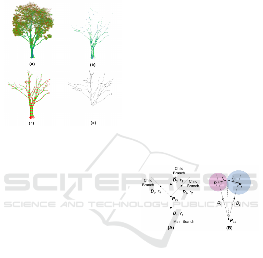
Figure 2: Stages of Branch Reconstruction. The different
stages of branch reconstruction is shown: (a) Original Point
Cloud, (b) Classification by Trunk-sampled Parameters, (c)
Shortest Path Tracing and (d) Cluster Connectivity Graph.
connectivity, represented by the function →, with the
exception of the cluster containing the root of the tree.
To establish the downward connectivity for C
i
, a path
traversal to the root for each point within the cluster
is performed. Once the path reaches a point of a dif-
ferent cluster, C
j
, a downward connection is formed,
i.e., C
i
→ C
j
. However, it is possible that points in the
same cluster have different paths to the root, thereby
forming connections with multiple clusters. In this
situation, the cluster which has the highest number
of connections forms the final downward connectivity
with it. Upward connectivity for the clusters can then
be inversely inferred. Clusters with multiple upward
connectivities are termed as joint nodes, while those
with single upward connectivity are termed as branch
nodes. An illustration depicting the connectivities of
clusters is shown in Fig. 2(d).
The centroid of each node can be computed as the
average location of all the points located within it. An
additional thickness parameter is attached to all the
branch nodes. The thickness parameter is estimated
by first projecting all the points onto a plane defined
by its centroid and a normal direction, estimated us-
ing the vector direction from itself to clusters which it
has a connection with. The average distance of all the
projected points to the centroid is taken to the node
thickness. Both the centroid and the thickness param-
eter are used in the subsequent sections for generating
the surface mesh of the tree branch model. The full
connectivity graph is termed the skeletal tree model.
4 SKIN SURFACES
Skin surfaces were introduced as a new paradigm for
defining smooth surfaces through the simple combi-
natorial of spheres. A skin surface S
B
is defined by
a set of spheres B in R
3
and a shrink factor s, where
0 ≤ s ≤ 1. It is the closed group of the infinite set of
spheres derived from B formed through convex com-
bination and shrinking. For further reading on the
mathematical formulation, we refer to (Edelsbrunner,
1999). There have been efficient algorithms, such as
(Cheng and Shi, 2009), which allow mesh surfaces
with guaranteed quality to be generated. In our imple-
mentation, we make use of an available package from
CGAL (CGAL, 2019) (Computational Geometry Al-
gorithm Library) which provides a closed manifold
surface mesh over the skin surface as defined through
an input array consisting of a group of spheres and a
shrink factor. The shrink factor allows for the con-
trol and tuning of the contouring surface shrinkage
between spheres. Other works such as (Li et al.,
2015) uses direct interpolation instead to form sur-
faces, which would require more sphere placements
to achieve the same contouring effect.
Figure 3: Computation of Sphere Position. A partial il-
lustration of the tree joint connectivity is shown in (A). The
ideal geometrical configuration for a pair of spheres B
i
and
B
j
is shown in (B).
4.1 Modelling Tree Joints
In a skeletal tree model, any node that is connected
to three or more distinct nodes is defined as a tree
joint. Each node has an associated thickness and a
centroid location. Using the thickness and position
of its connected nodes, a skin surface is constructed
around the tree joint node. Once the skin surface
for the tree joint is generated, a half-sphere region
corresponding to each connecting branch is identified
and removed from the skin surface, creating a circu-
lar opening. This circular opening would be used as a
mesh-connecting conduit with the cylindrical surface
mesh used for the mesh model of the branches, i.e.,
nodes with only two or fewer connections.
GRAPP 2020 - 15th International Conference on Computer Graphics Theory and Applications
86
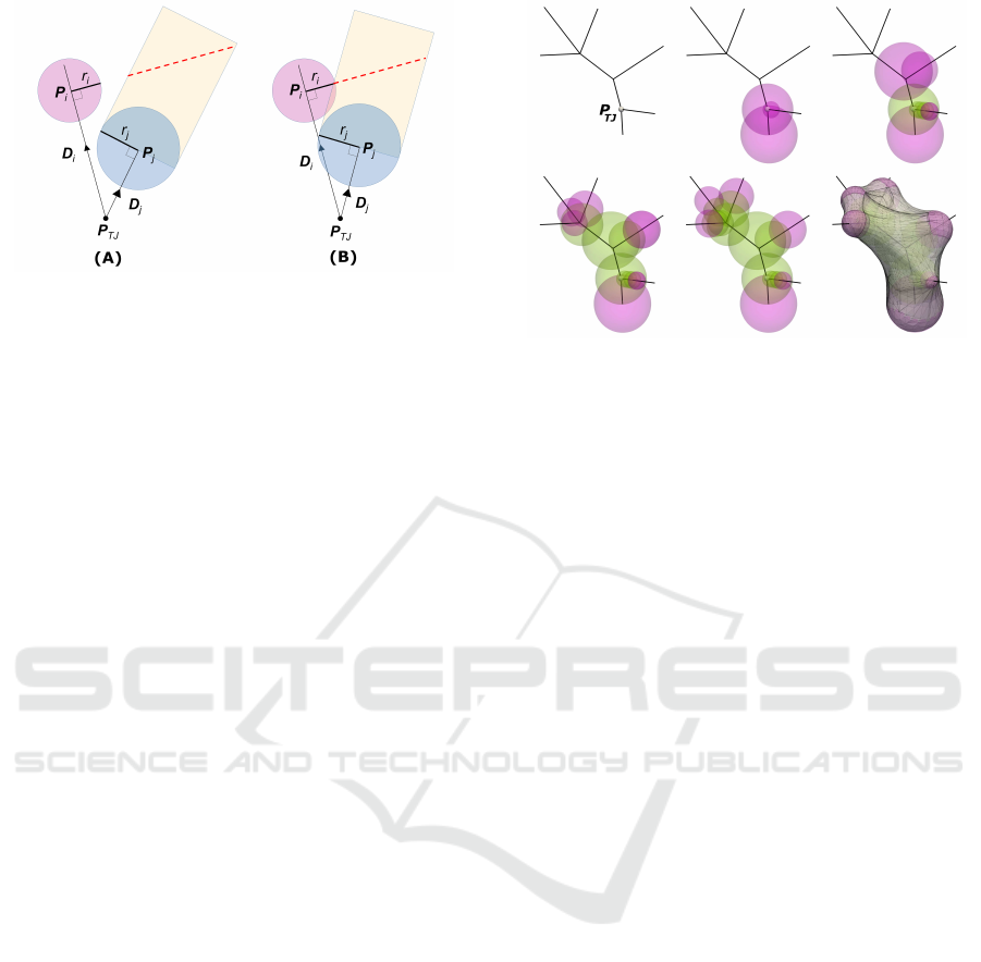
Figure 4: Intersection Test. Two different ball configuration
with different intersection outcomes. There is no intersec-
tion in (A) while there is one in (B).
4.1.1 Ideal Balls Placement
To generate the skin surface, a set of spheres B =
{B
1
·· ·B
n
} must be specified, along with a shrink fac-
tor s. Each B
i
contains two parameters, its position P
i
and radius r
i
. For s, a constant of 0.25 is employed
throughout our implementation for a look similar to
actual trees. Let P
TJ
be the centroid of a tree joint
TJ with n number of connecting branches, with their
vector directions termed as
−→
D
1
to
−→
D
n
and radii as
r
1
to r
n
(see Fig. 3A). Let
−→
D
1
be the main branch
while
−→
D
2
to
−→
D
n
are the child branches. The resulting
skin surface mesh should be such that when the set of
cylindrical rays, as defined by
−→
D
1
to
−→
D
n
and r
1
to r
n
,
are projected onto it, it will result in distinct and non-
intersecting patches. To achieve this goal, the set of
spheres placement to construct the skin surface should
be such that a half-sphere region for each sphere, cor-
responding to each branch, should be unobstructed by
other spheres.
The test can be conducted to check for intersection
based on the 2D illustration shown in Fig. 4. In (A),
a rectangular projection based on
−→
D
j
is intersected
with the perpendicular line defined by the orthogonal
line to
−→
D
i
and the point P
i
. The result of that inter-
section is the red dotted line. If the red dotted line
comes within a distance of r
i
to P
i
as shown in (B),
then an intersection is deemed to have occurred. In
the 3D case, the intersection test is between an ellipse
(resulting from an angled planar cut of the cylinder)
and a sphere.
4.1.2 Ball Generation
In Figure 3B, the ideal position of B
i
and B
j
can be
solved geometrically. However, the restriction lies in
the length of the branch, which might not be able to
accommodate in cases of tight angle difference. As
P
i
can only lie along the vector P
TJ
+ k
i
−→
D
i
, where k
i
Figure 5: Ball Generation Process. The series of images
depict the ball generation process for a single joint. Green
sphere are in the dormant set, while pink spheres are in the
active set. The final image on the lower right shows the skin
surface model.
is a scalar, there is a limit to the value of k. This is
constrained by the length of the immediate distance to
the next branch node. Hence, the path which B
i
can
lie upon follows the upward connectivity from branch
node to branch node. Therefore, an iterative approach
is required to generate the spheres.
The sequence of images, as depicted in Fig. 5,
shows the sequence of ball placements used to form
the skin surface for a tree joint. At the start of the
process, n number of spheres (equal to the number
of connected nodes) are generated and placed in set
B
active
(pink spheres). Each P
i
is initialized to the po-
sition P
TJ
+ r
i
−→
D
i
. The sphere’s radius parameters fol-
low directly from its corresponding branch’s radius.
This ensures that each half-sphere region is distinct
on the eventual skin surface mesh. We then iteratively
compare each possible pair of spheres in B
active
, using
the cylindrical projection approach shown in Fig. 4.
Once the projection from B
i
is determined to intersect
with another sphere B
j
, B
i
is duplicated and placed in
another set B
dormant
(green spheres). The B
i
in B
active
is then updated with its new position with k
i
= k
i
+ r
i
.
4.1.3 Merging of Tree Joints
In the event where k
i
> |P
TJ
− P
BN
|, where BN is the
next upward connected branch node, B
i
is similarly
duplicated and added to B
dormant
while updated with
its new position with P
BN
. We then merge the tree
joint with the newly intersected tree joint, spawning
m number of new child branches and the associated
new set of spheres B
new
= {B
1
·· ·B
m
}. The inter-
sected sphere B
i
is added to B
dormant
and discarded
from B
active
, while B
new
is added to it. The process
of testing for cylindrical intersection repeats. The fi-
Generation of Tree Surface Mesh Models from Point Clouds using Skin Surfaces
87
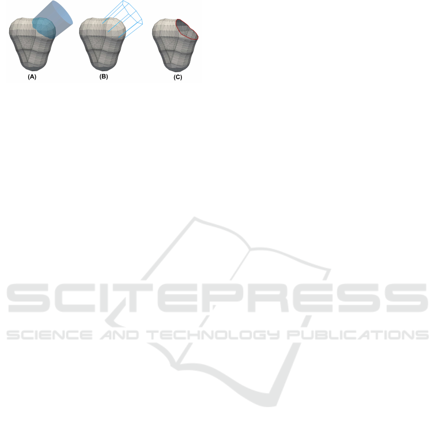
Figure 6: Half-Sphere Region Removal. In (A), a cylindri-
cal projection based on the connecting branch direction and
radius is projected onto the skin model. Based on an inter-
section test made at every 45
◦
interval as illustrated in (B), a
new point is added to the skin mesh surface. A planar walk
connecting all the points is executed and the half-surface
region is removed in (C).
nal tree joint model is created by using the two sets of
spheres listed in B
active
and B
dormant
. In Fig. 5, three
joints are shown and merged together as a single one.
The whole process stops when none of the spheres in
B
active
intersects with another.
4.2 Half Sphere Removal
To create a half-sphere opening for attachment with
the cylindrical mesh surfaces of the branch nodes,
the half-sphere region corresponding to each ball in
B
active
is required to be removed for connecting to the
branches. To identify the set of surface triangle ele-
ments corresponding to that half-sphere region, a con-
nected edge path delineating the border of the half-
sphere region has to be formed on the skin mesh sur-
face. Due to the nature of how the skin surface is
formed, using a planar cut would not likely provide a
satisfactory result due to the smoothed curved surface
resulting from multiple nearby spheres. Instead, we
first project points and add points onto the skin sur-
face at every 45
◦
interval based on a cylindrical ray
projection with the corresponding
−→
D and r parame-
ters of the child branch (see Fig. 6A & 6B). Next,
a planar walk on the surface creates the edge path
connectivity between each pair of adjacent projected
points. Each planar path lies on the intersection be-
tween the skin model and the plane formed by the pair
of adjacent projected points and the center of the inci-
dent sphere. The resulting mesh with the half-sphere
region removed is shown in Figure 6C.
5 QUADRILATERAL PATCH
GENERATION
Structured quadrilateral meshes offer many numeri-
cal advantages over unstructured meshes due to their
tensor product structures. However, the generation of
quadrilateral meshes is not trivial. In this section,
we explore a potentially viable approach to gener-
ate 6-sided patches on the tree joint triangular-based
meshes that are constructed based on an intrinsic De-
launay triangulation of the points at the tip of the
spheres in B
active
. Our approach takes reference from
works (Boier-Martin et al., 2004; Daniels II et al.,
2011), which use the concept of Voronoi regions to
decompose the underlying triangular base mesh into
separate domains, where further parametrization into
quadrilaterals can take place.
The quadrilateral patch decomposition is applied
to a tree joint node taken from the Khaya senegalen-
sis example, see Figure 8. Prior to the removal of the
half-sphere region (Figure 6B), tip-points are placed
for each B
i
at the position P
TJ
+ (k
i
+ r
i
)
−→
D
i
. Using
these tip-points, a Voronoi decomposition of the tree
joint model is applied (Figure 8A). The dual Delaunay
graph constitutes triangular connectivity between the
tip points. Geodesic paths are then plotted between
points with such connectivity (Figure 8B). Once the
half-sphere regions are removed from the base-mesh
(Figure 6C), the intersected portions of the geodesic
paths are removed and merged with the boundary, ef-
fectively forming 6-sided patches (Figure 8C).
A particular case can arise when one of the
geodesic path intersects with the half-sphere from the
opposite vertex in the triangulation, resulting in the
formation of two distinct quadrilateral patches. In
most cases, the 6-sided patches can be split relatively
easily into quadrilaterals using a 6-valence singular-
ity at the barycentric point. However, other config-
urations such as using two 5-valence singularities or
methods such as multi-block decomposition (Fogg
et al., 2013) can be adopted depending on the skew-
ness of the 6-sided patch. Each quadric patch can
then be quad-meshed with added singularity points,
depending on its aspect ratio.
6 RESULTS
We implemented our algorithm on a LiDAR scan
dataset of a group of trees along a roadside in Sin-
gapore. Each individual tree underwent the branch-
leaf classification process and the result is shown in
Fig 7. Based on the estimated parameters from the
lower trunk regions of each tree, most of the first
few branching orders can be seen to be classified (red
coloured) with good accuracy. For trees with sparser
leaf densities, especially for larger trees, the classifi-
cation can even reach the higher-order (and thinner)
branches.
GRAPP 2020 - 15th International Conference on Computer Graphics Theory and Applications
88
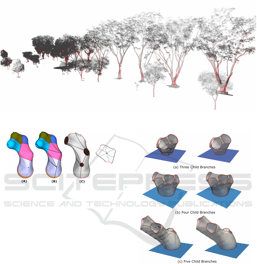
Figure 7: Branch Classification. The classification result of a group of trees, the points corresponding to woody regions are
coloured red.
Figure 8: Generating Quadrilateral Patches. The series of
images illustrate the patch generation process - (A) Voronoi
patches based on sphere tips, (B) Intrinsic Delaunay trian-
gulation, (C) 6-sided patches and the proposed quadrilateral
configuration (left to right).
Using the classified branch points, the skeletal
tree model and the tree surface model are recon-
structed. The tree joint generation algorithm is imple-
mented using C++, utilizing packages from CGAL.
The two main packages used are skin surface mesh
for skin surface generation, fast intersection and dis-
tance computation (AABB Tree) for point projection
on the surface mesh.
To test the validity of our tree joint construction
approach, we generate tree joints using multiple ran-
domly generated child branch directions and radii.
The results are shown in Fig. 9 for three, four, and
five child branches. The meshes on the left are di-
rectly generated using the CGAL skin surface pack-
age. CGAL offers further functionalities for a pro-
gressive surface subdivision that reduces the error
with respect to the mathematical formulation of the
skin surface. However, the resulting mesh quality can
be quite poor (see Figure 6 for an example). Hence,
a CGAL remeshing operation is applied to achieve a
smooth mesh surface with good qualities, as shown
on the right of Fig. 9.
Figure 9: Tree Joint Meshes. The following tree joint
meshes were created randomly with varying number of
child branches. The original mesh created using CGAL’s
skin surface is shown on the left, while the resmeshed ver-
sion is shown on the right.
6.1 Classification and Tree Skeletal
Model
We tested our algorithm on five commonly found tree
species in Singapore from the LiDAR dataset. These
are Tabebuia rosa, Swietenia macrophylla, Samanea
saman, Peltophorum pterocarpum and Khaya sene-
galensis. The result of the classification process and
the subsequent skeletal tree extraction is shown in
Generation of Tree Surface Mesh Models from Point Clouds using Skin Surfaces
89
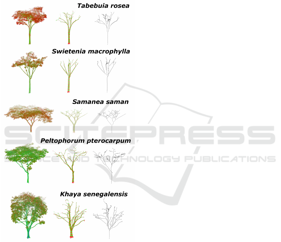
Fig 10. The original points are shown and coloured
based on their intensity values. From lowest to high-
est intensities, the corresponding color gradient goes
from red to green and then finally blue. As high-
lighted based on the color distribution, it can be seen
that the range of intensities differs from tree to tree,
depending on conditions such as the amount of sun-
light, temperature, or weather conditions.
Figure 10: Skeletal Tree Generation. The original point
clouds are shown on the left, the classification results in the
middle, and the skeletal tree model are shown on the right.
The classification is often most robust at the trunk
region since the sampling parameters were taken from
there. However, the fuzziness grows as it moves in-
wards in the crown region. This is to be expected:
the foliage affects the surface region of the branches
which the laser scanner can reach. A further pruning
operation is performed on the skeletal model to en-
sure that awkward (usually erroneous) connectivities
with large bending angles are removed.
Typically for point clouds acquired through laser
scanner, multiple passes are often merged together to
cover all sides of a tree. Slight variation during regis-
tration can result in overlapping surfaces. Depending
on other factors such as occlusion or weather condi-
tions, it can cause unevenness in the distribution of
points throughout the tree. Very often, manual adjust-
ment of parameters of intensity and sparsity can result
in superior classification results. In our case, we are
able to recover the first few tree branching order quite
accurately just by using the automated trunk-based
parameter estimation approach. Our current tree clas-
sification approach is a ”quick-and-dirty” that works
relatively well, and noted other more involved algo-
rithms such as (Vicari et al., 2019) and usage of ma-
chine learning approaches for point cloud classifica-
tion (Wang et al., 2017).
6.2 Surface Mesh Generation
Each of the five skeletal models generated from the
point clouds is used to generate a surface mesh of the
tree branching structure. A skin model is created for
each joint node in the skeletal model. The five surface
mesh tree models are shown in Fig 11. A few exam-
ples of the tree joints created using skin surface model
are shown on the right. A real tree can have very intri-
cate branching morphology, and some tree joints can
have up to 6 to 8 child branches. The generated tree
joints shown have smooth surfaces that mimic the ac-
tual tree surfaces. Furthermore, its simple construc-
tion approach based on a collection of spheres allows
it to be employed as a suitable intermediary model for
generating the complex branching structures of trees,
no matter the morphology.
Like any real-world data acquisition, it can be
subjected to noise and other external environmental
variables such as occlusion, leading to partial cov-
erage of branches. As such, radius estimate might
vary widely even along the same branch. Hence, all
radii along a branch (i.e., branch nodes that lies be-
tween two joints) are averaged out. This is why cylin-
ders are used as an approximation shape model rather
than cones. Additionally between the child and par-
ent branches, the general rule to follow is by using
Leonardo da Vinci’s rule (i.e., the sum of the cross-
sectional area of all tree branches above a branch-
ing point at any height is equal to the cross-sectional
area of the trunk or the branch immediately below the
branching point). An initial check of all node radii
is conducted, and in cases where significant discrep-
ancies occur, usually due to inadequate sampling, a
filtering operation is applied to ensure that it adheres
to this rule.
GRAPP 2020 - 15th International Conference on Computer Graphics Theory and Applications
90
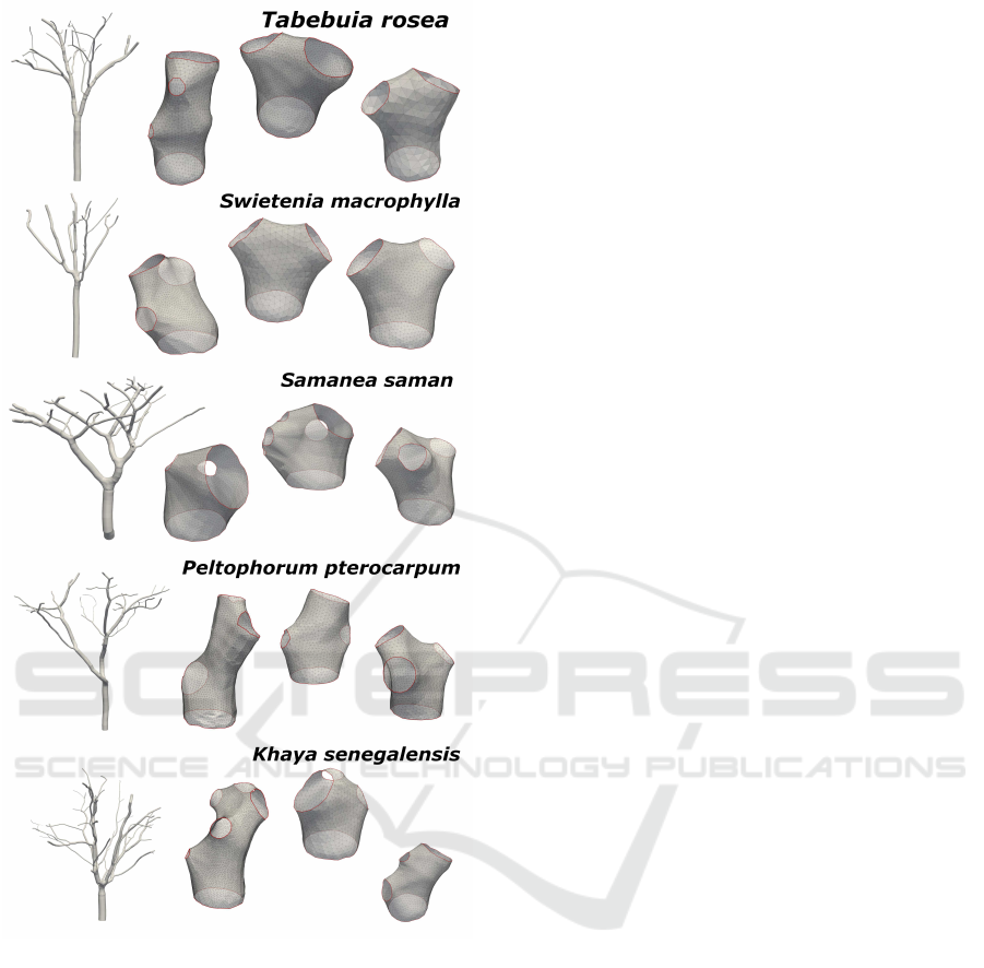
Figure 11: Full Meshed Model of the Trees. The five point
cloud test data is meshed and a few of the tree joint models
used are shown on the right.
The remeshing operation applied on the meshed
skin model can be adjusted to select for edge length.
Since the lower part of the tree can be substantially
larger in size than the upper region, a size-invariant
measurement has to be applied to preserve the mod-
elling accuracy, especially for the thinner branches.
For consistent preservation of details, the average
edge length of a tree joint mesh is set to be 1/30
th
of the smallest circular boundary created by the half-
sphere removal. This ensures that all cylindrical
branches, no matter the size, will have the same mesh-
ing density.
7 DISCUSSION AND
CONCLUSION
The intent of this work is to address the issue of con-
structing a simulation-ready 3D finite element mesh
model from point clouds of trees. A surface mesh
model of a tree typically has multiple long slender
branches that can be quite challenging to generate a
volumetric mesh. Hence, a piecewise model approach
such as ours wouldfacilitate the volumetric mesh gen-
eration process as the cylindricalbranches and the tree
joint models can be handled separately. By using a
template surface on each of the half-sphere openings,
and also on the cylindrical branch models, both can
be meshed separately and then merged. Furthermore,
a piecewise model facilitates the assignment of dif-
ferent material properties on various parts of the tree,
such as between trunk and branches.
We have also applied the tree surface mesh
generation for various tree species models which
were procedurally created based on L-system growth
rules (Gobeawan et al., 2019). The artificially created
tree is often written into an MTG file format (Godin
et al., 1999), which contains branching connectivities
and radii data that are sufficient for our method.
In conclusion, this paper describes an approach
to make use of skin surfaces as a representation of
tree joints. It facilitates the construction of a full tree
surface mesh from a skeletal model extracted from a
laser-scanned point cloud. Among the many works,
we find that the approach of (Ji et al., 2010) has
many similarity with our skin surface approach for
modelling complex joints, as used in (Zhu et al.,
2015). A proposed extension is to make comparison
studies between their approach and ours. Our future
work includes both improving our quadrilateral patch
formulation and exploring the formation of 3D finite
elements, both tetrahedral and hexahedral, using our
proposed piecewise tree joint construction method.
REFERENCES
Belton, D., Moncrieff, S., and Chapman, J. (2013). Process-
ing tree point clouds using gaussian mixture models.
Proceedings of the ISPRS Annals of the Photogram-
metry, Remote Sensing and Spatial Information Sci-
ences, Antalya, Turkey, pages 11–13.
Bloomenthal, J. (1985). Modeling the mighty maple. In
ACM SIGGRAPH Computer Graphics, volume 19,
pages 305–311. ACM.
Boier-Martin, I., Rushmeier, H., and Jin, J. (2004). Pa-
rameterization of triangle meshes over quadrilateral
domains. In Proceedings of the 2004 Eurograph-
Generation of Tree Surface Mesh Models from Point Clouds using Skin Surfaces
91

ics/ACM SIGGRAPH symposium on Geometry pro-
cessing, pages 193–203. ACM.
Bucksch, A. and Lindenbergh, R. (2008). Campino—a
skeletonization method for point cloud processing. IS-
PRS journal of photogrammetry and remote sensing,
63(1):115–127.
Cao, J., Tagliasacchi, A., Olson, M., Zhang, H., and Su,
Z. (2010). Point cloud skeletons via laplacian based
contraction. In 2010 Shape Modeling International
Conference, pages 187–197. IEEE.
CGAL (2019). CGAL User and Reference Manual. CGAL
Editorial Board, 4.14 edition.
Cheng, H.-L. and Shi, X. (2009). Quality mesh generation
for molecular skin surfaces using restricted union of
balls. Computational Geometry, 42(3):196 – 206.
Daniels II, J., Lizier, M., Siqueira, M., Silva, C. T., and
Nonato, L. G. (2011). Template-based quadrilateral
meshing. Computers & Graphics, 35(3):471–482.
Edelsbrunner, H. (1999). Deformable smooth surface de-
sign. Discrete & Computational Geometry, 21(1):87–
115.
Fogg, H. J., Armstrong, C. G., and Robinson, T. T. (2013).
Multi-block decomposition using cross-fields. Pro-
ceedings of adaptive modelling and simulation, Lis-
bon, pages 254–267.
Gobeawan, L., Lin, E., Tandon, A., Yee, A., Khoo, V., Teo,
S., Yi, S., Lim, C., Wong, S., Wise, D., et al. (2018).
Modeling trees for virtual singapore: From data ac-
quisition to citygml models. International Archives of
the Photogrammetry, Remote Sensing & Spatial Infor-
mation Sciences, 42.
Gobeawan, L., Wise, D. J., Yee, A. T. K., Wong, S. T.,
Lim, C., Lin, E. S., and Su, Y. (2019). Convenient
tree species modeling for virtual cities. In Advances
in Computer Graphics - 36th Computer Graphics
International Conference, CGI 2019, Calgary, AB,
Canada, June 17-20, 2019, Proceedings, pages 304–
315.
Godin, C., Ccostes, E., and Sinoquet, H. (1999). A
method for describing plant architecture which in-
tegrates topology and geometry. Annals of Botany,
84(3):343–357.
Hackenberg, J., Morhart, C., Sheppard, J., Spiecker, H., and
Disney, M. (2014). Highly accurate tree models de-
rived from terrestrial laser scan data: A method de-
scription. Forests, 5:1069–1105.
Hu, S., Li, Z., Zhang, Z., He, D., and Wimmer, M.
(2017). Efficient tree modeling from airborne lidar
point clouds. Comput. Graph., 67(C):1–13.
Huang, H., Wu, S., Cohen-Or, D., Gong, M., Zhang, H., Li,
G., and Chen, B. (2013). L1-medial skeleton of point
cloud. ACM Trans. Graph., 32(4):65–1.
Ji, Z., Liu, L., and Wang, Y. (2010). B-mesh: a modeling
system for base meshes of 3d articulated shapes. In
Computer Graphics Forum, volume 29, pages 2169–
2177. Wiley Online Library.
Li, P., Wang, B., Sun, F., Guo, X., Zhang, C., and Wang, W.
(2015). Q-mat: Computing medial axis transform by
quadratic error minimization. ACM Transactions on
Graphics (TOG), 35(1):8.
Li, R., Bu, G., and Wang, P. (2017). An automatic tree
skeleton extracting method based on point cloud of
terrestrial laser scanner. International Journal of Op-
tics, 2017:1–11.
Livny, Y., Yan, F., Olson, M., Chen, B., Zhang, H., and
El-Sana, J. (2010). Automatic reconstruction of tree
skeletal structures from point clouds. ACM Trans.
Graph., 29(6):151:1–151:8.
Pfeifer, N., Gorte, B., Winterhalder, D., et al. (2004). Au-
tomatic reconstruction of single trees from terrestrial
laser scanner data. In Proceedings of 20th ISPRS
Congress, volume 35, pages 114–119. ISPRS Istan-
bul.
Poh, H., Lim, C., Ge, Z., Wise, D., Lou, J., Eng, Y., Lin, E.,
Burcham, D., Li, K., Lee, I., Chang, S., Chan, W.-L.,
Lee, H., and Khoo, B. (2019). Fractal tree geometry
reconstruction and meshing: From point cloud model
to tree aerodynamic simulation. In The Eighth Inter-
national Symposium on Physics of Fluids (ISPF8).
Raumonen, P., Kaasalainen, M.,
˚
Akerblom, M.,
Kaasalainen, S., Kaartinen, H., Vastaranta, M.,
Holopainen, M., Disney, M., and Lewis, P. (2013).
Fast automatic precision tree models from terrestrial
laser scanner data. Remote Sensing, 5:491–520.
Soon, K. and Khoo, V. (2017). Citygml modelling for singa-
pore 3d national mapping. The International Archives
of Photogrammetry, Remote Sensing and Spatial In-
formation Sciences, 42:37.
Su, Z., Zhao, Y., Zhao, C., Guo, X., and Li, Z. (2011).
Skeleton extraction for tree models. Math. Comput.
Model., 54(3-4):1115–1120.
Tagliasacchi, A., Zhang, H., and Cohen-Or, D. (2009).
Curve skeleton extraction from incomplete point
cloud. ACM Trans. Graph., 28(3):71:1–71:9.
Vicari, M. B., Disney, M., Wilkes, P., Burt, A., Calders,
K., and Woodgate, W. (2019). Leaf and wood clas-
sification framework for terrestrial lidar point clouds.
Methods in Ecology and Evolution, 10(5):680–694.
Wang, D., Hollaus, M., and Pfeifer, N. (2017). Feasibility
of machine learning methods for separating wood and
leaf points from terrestrial laser scanning data. ISPRS
Annals of Photogrammetry, Remote Sensing & Spatial
Information Sciences, 4.
Xie, D., Wang, X., Qi, J., Chen, Y., Mu, X., Zhang, W., and
Yan, G. (2018). Reconstruction of single tree with
leaves based on terrestrial lidar point cloud data. Re-
mote Sensing, 10:686.
Xu, H., Gossett, N., and Chen, B. (2007). Knowledge and
heuristic-based modeling of laser-scanned trees. ACM
Trans. Graph., 26(4).
Yan, D., Wintz, J., Mourrain, B., Wang, W., Boudon, F., and
Godin, C. (2009). Efficient and robust reconstruction
of botanical branching structure from laser scanned
points. In 2009 11th IEEE International Conference
on Computer-Aided Design and Computer Graphics,
pages 572–575.
Zhu, X., Jin, X., and You, L. (2015). High-quality tree
structures modelling using local convolution surface
approximation. The Visual Computer, 31(1):69–82.
GRAPP 2020 - 15th International Conference on Computer Graphics Theory and Applications
92
