
Towards Abstract Test Execution in Early Stages of Model-driven
Software Development
No
¨
el Hagemann
a
, Reinhard Pr
¨
oll
b
and Bernhard Bauer
c
Software Methodologies for Distributed Systems, University of Augsburg, Augsburg, Germany
Keywords:
Test Execution, Model-based Testing, Domain-specific Modeling, Model-driven Software Development.
Abstract:
Over the last decades, systems immanent complexity has significantly increased. In order to cope with the
emerging challenges during the development of such systems, modeling approaches become an indispensable
part. While many process steps are applicable to the model-level, there are no sufficient realizations for test
execution yet. As a result, we present a semi-formal approach enabling developers to perform abstract test
execution straight on the modeled artifacts to support the overarching objective of a shift left of verification
and validation tasks. Our concept challenges an abstract test case (derived from test model) against a system
model utilizing an integrated set of domain-specific models, i.e. the omni model. Driven by an optimistic
dataflow analysis based on a combined view of an abstract test case and its triggered system behavior, possible
test verdicts are assigned. Based on a prototypical implementation of the concept, the proof of concept is
demonstrated and further on put in the context of related research.
1 INTRODUCTION
The steadily raising complexity of application soft-
ware may hardly be tackled by traditional develop-
ment techniques. In order to reduce the complexity,
the concepts of abstraction and automation are used in
many development phases. While concepts and tools
in the areas of executable modeling languages, model
simulation, formal verification and model-based test-
ing (MBT) show promising results on the way to-
wards model-centric development methodologies, the
main focus is on generating code from these models.
Apart from formal approaches for verification, none
of the mentioned techniques provides any significant
verification steps during development until the model-
to-code transformation is performed, either in a man-
ual or automated way. It is a well-known fact, that
faults introduced in early stages of development, de-
mand significantly more money and time for fixing,
than faults induced in later phases (Planning, 2002)
(Galin, 2004). Further, Jones et al. gave insights
about the most prominent development phases, where
defects are revealed, namely the late testing phases
(Jones, 2008).
a
https://orcid.org/0000-0001-9441-9889
b
https://orcid.org/0000-0002-3979-5483
c
https://orcid.org/0000-0002-7931-1105
1.1 Problem Statement
Based on the insight on impacts of design time faults
together with the steadily raising complexity of to-
day’s software, we follow a real shift left of verifica-
tion and validation (V & V) activities in model-driven
development processes. Apart from formal verifica-
tion approaches like model checking, and informal
techniques like reviews, which most of the time close
the gap between specification and code, up to our
knowledge there is no semi-formal and (semi-) au-
tomated technique for early stages of model-driven
software development (MDSD). Therefore, we see a
strong need for a semi-formal approach to perform
abstract test execution in model-driven development
processes.
In order to achieve this ambitious goal, we com-
bine concepts of model-based testing with model in-
terpretation mechanisms powered by dataflow anal-
ysis on models. Starting from an integrated model
basis, made up of domain-specific models used dur-
ing software and test development together with an
integration component, the combined dataflow is an-
alyzed. This means the model artifacts specified in
the constructive phases are linked with the test model
to perform an abstract execution of test cases. De-
pending on the level of concreteness and complete-
ness of model artifacts, the analysis results may ei-
216
Hagemann, N., Pröll, R. and Bauer, B.
Towards Abstract Test Execution in Early Stages of Model-driven Software Development.
DOI: 10.5220/0008934802160226
In Proceedings of the 8th International Conference on Model-Driven Engineering and Software Development (MODELSWARD 2020), pages 216-226
ISBN: 978-989-758-400-8; ISSN: 2184-4348
Copyright
c
2022 by SCITEPRESS – Science and Technology Publications, Lda. All rights reserved

ther be seen as a problem indication during ongoing
modeling work or as a first verification step before
code-based processing. In a more general context,
the possibility to evaluate abstract test case specifi-
cations against models of the system may fit into the
context of a model-based software testing lifecycle
as sketched in earlier work of Pr
¨
oll et al. (Pr
¨
oll and
Bauer, 2018b).
1.2 Outline
Starting off with Section 2, basic terms, definitions,
and a case study are given in order to narrow down
the context of our work. Based on these basic building
blocks, Section 3 presents the core concept for the ab-
stract test execution, which splits up into three phases
featuring the major processing steps of our approach.
Based on the case study and a prototypical implemen-
tation, a proof of concept for our approach is done
(Section 4). Therefore, Section 4.1 introduces the
setup, before the results are presented in Section 4.2.
In order to be able to classify the presented approach
in the context of other approaches, related work is pre-
sented in Section 5. Finally, Section 6 draws a con-
clusion and gives an outlook on future work in this
area.
2 PREPARATORY STEPS
The term domain is used in multiple contexts, with
different semantics. In this paper the term domain
is used in a sense of a technical domain of a model-
driven development approach, like requirements mod-
eling or safety engineering, which may also be carried
out in a model-based fashion.
For MDSD as well as MBT the number of
domain-specific modeling languages steadily raises.
Apart from the specific language constructs, all the
MDSD approaches share the goal of ending up with
an adequate specification of the System Under Devel-
opment (SUD), i.e. System Under Test (SUT). We
call this specification artifact the system model.
In parallel, the testing domain makes use of de-
scriptions of the intended system behavior to sub-
sequently derive tests for the SUD in an automated
way. Such descriptions may either be integrated in
the system model or modeled separately. Both pos-
sibilities have pros and cons (see Pretschner et al.
(Pretschner and Philipps, 2005)). Having in mind the
trend towards automation of error-prone steps, e.g. re-
placing the manual transformation of specifications to
code with code generators, we decided to follow a
separated model approach. Therefore, the term test
Integration ModelSystem Model Test Model
Requirements
Figure 1: Orchestration of domain-specific models.
model represents a model artifact apart from the sys-
tem model, derived from a shared set of requirements
with the intention to generate test cases for subse-
quent V & V tasks (Apfelbaum and Doyle, 1997).
The system model as well as the test model spec-
ify the actual and intended sequences of actions. As
originally defined by Apfelbaum et al., a common
concept is the so called path, determining “a se-
quence of events or actions that traverse through the
model” (Apfelbaum and Doyle, 1997). The intended
sequences of actions derived from a test model, i.e.
paths, are better known as test cases. Closely linked
to the path concept, the so called guards are an in-
evitably contained concept for conditional parts of the
specified system model or its test counterpart.
2.1 Metamodel Concepts
The separation of the system and test model, demands
for additional concepts managing the interaction of
models across multiple domains. Introduced by Proell
et al. (Pr
¨
oll et al., 2017), the omni model approach
deals with the orchestration of a flexible set of model
artifacts. Figure 1 illustrates the role of the model
artifact bridging the conceptual gap, namely the inte-
gration model.
2.1.1 Integration Model
Basically, the integration model is designed for two
main purposes. On the one hand, the model artifact
should give the modeler the possibility to specify a
coarse sketch of how the SUD may be hierarchically
decomposed into its basic building blocks. The itera-
tive alignment of the hierarchical decompositions de-
fined in the integration model as well as the system
model allows us to maintain model mappings without
affecting the original system model, in a sense of sep-
aration of concerns. Further, it gives the flexibility to
manage varying levels of granularity and interpreta-
tion across the domain-specific model artifacts.
Towards Abstract Test Execution in Early Stages of Model-driven Software Development
217

On the other hand, the integration model includes
concepts for the mapping of abstract states of be-
havioral models across domains (lower part of Fig-
ure 1). Thereby, model artifacts included in a certain
path of the system model may explicitly be mapped
to elements of a test case, derived from the respec-
tive test model. Especially in scenarios, where system
and test modeling is carried out on different domain-
specific languages the mapping of concepts cannot be
achieved automatically. All in all, this allows us to
perform an abstract execution of a test case, which is
detailed in Section 3.
Depending on the applied development methodol-
ogy, the creation and maintenance of the integration
model artifacts may either be achieved in an auto-
mated fashion or requires some manual modeling by
the respective systems engineer. Especially, the main-
tenance of the mapping information across modeling
domains demands for manual adjustments, in case of
separated models for system and test modeling. The
extra work to be done here, is expected to pay off dur-
ing test iterations on the model-level, revealing con-
ceptual defects of the SUD and thereby drastically re-
ducing the cost for fixing defects.
2.1.2 System Model
Derived from an initial requirements model (see Fig-
ure 1), there are many domain-specific and general-
purpose modeling languages, which serve the pur-
pose of MDSD. For example, the Unified Model-
ing Language (UML) represents the most prominent
general-purpose modeling language used in software
development (OMG, 2011). Being published as a
standard alongside the Meta Object Facility (MOF),
it gained popularity and therefore is widely known
(OMG, 2002). Due to the huge amount of model-
ing capabilities and its vague semantics, many profiles
and subsets for specific needs have emerged.
All these modeling languages have in common,
that they share concepts for the specification of struc-
tural as well as behavioral descriptions of the SUD.
Thereby, the palette for modeling behavior may fur-
ther be categorized into concepts, either verifying or
modifying the current system state. For example, the
case study analyzed in Section 4 uses UML state
charts to specify its behavior. Therein, state nodes’
actions represent modifying model elements, while
state transitions with annotated guards mark a veri-
fying concept.
2.1.3 Test Model
The same holds for the test domain, where many mod-
eling languages are usable or at least adaptable for
test specification tasks. SysML is one possibility for
modeling V & V concepts of a SUD. Further, there is
an UML profile named UML Testing Profile (UTP),
which was explicitly designed to serve as a model-
ing profile for MBT activities (Object Management
Group (OMG), 2004). Throughout the case study, we
use a reduced and customized version of UML activ-
ity charts to specify the test models, taking the core
concepts of UTP and SysML into account. Thereby,
the activity elements are distinguished by their stereo-
type. On the one hand, the stereotype verification
point determines activities, checking the current sys-
tem state against specified criteria. On the other hand,
the stereotype test step marks an activity, which sends
stimuli to the SUD by manipulating variables. Apart
from the activity elements, the connectors may spec-
ify guards, in turn controlling the subsequent genera-
tion of test cases via path extraction.
To summarize, the included model elements may
again be categorized, either following a verifying or
modifying purpose, later on reflected by appropriate
Execution Graph ++ (EGPP) Model elements.
For the system and test model information, a sen-
sitive point in the process is given by the M2M trans-
formation from the respective modeling languages to
our internal representation, which is introduced in the
following section.
2.1.4 Execution Graph++ Model
As already mentioned in the previous sections, it is
desirable to lift the original model to an independent
representation, which serves for internal analysis pur-
poses. Therefore, we use the EGPP metamodel orig-
inally presented in prior work of Pr
¨
oll et al. as target
meta model for processing (Pr
¨
oll and Bauer, 2018a).
It also represents a basic concept for the Architecture
And Analysis Framework (A3F) prototype, carrying
out the functionality presented throughout this contri-
bution.
The metamodel includes concepts for modeling
hierarchical control flow graphs to capture the struc-
ture and behavior of mentioned test and system mod-
els (see EGPPNode, EGPPGraph). Further, a con-
cept dealing with additional or already processed in-
formation from source model artifacts is included (see
EGPPTaggedData, EGPPAttribute).
Altogether, the EGPP metamodel marks the cen-
tral metamodel artifact which allows us to flexibly ap-
ply to all kinds of constellations of domain-specific
modeling languages taking part in the respective de-
velopment setup. Although, the EGPP instances are
currently not used for implementation purposes, but
may be used in future versions, the potential for se-
mantic gaps between the original model artifact and
MODELSWARD 2020 - 8th International Conference on Model-Driven Engineering and Software Development
218
Initial
CRASH_FLASHING_PASSIVE
entry / cr_CrashFlas hing = 0;
CRASH_FLASHING_ACTIVE
entry / cr_CrashFlas hing = 1;
IMPACT_PENDING EM_SWITCH_PRESSED EM_SWITCH_SPV_PRESSED
[oc_CentralLockingRequest &&
(oc_CentralLockingStatus == 1)]
[cr_ImpactToggle && cr_ImpactX] [! db_EmSwitch]
[! cr_ImpactToggle && cr_ImpactX] [db_Em Switch]
[! in_Em SwitchSPV]
[in_EmSwitchSPV]
ActivityInitial
«TestStep»
_db_EmSwitch = 0
«TestStep»
_db_EmSwitch = 1
«TestStep»
_oc_CentralLockingRequest = 0
«TestStep»
_oc_CentralLockingRequest = 1
«TestStep»
_oc_CentralLockingStatus = 0
«TestStep»
_oc_CentralLockingStatus = 1
«TestStep»
_oc_CentralLockingStatus = 2
«VP»
_cr_CrashFlashing == 1
«VP»
_cr_CrashFlashing == 0
«TestStep»
_in_EmSwitchSPV = 1
«TestStep»
_in_EmSwitchSPV = 0
«VP»
_cr_CrashFlashing == 1
ActivityFinal
«TestStep»
_cr_ImpactToggle = 1
«TestStep»
_cr_ImpactX = 1
«TestStep»
_cr_ImpactToggle = 0
«TestStep»
_cr_ImpactX = 0
[oc_CentralLockingRequest &&
(oc_CentralLockingStatus == 1)]
[!o c_CentralLockingRequest ||
(oc_CentralLockingStatus != 1)]
[_cr_ImpactToggle && _cr_ImpactX]
[!_ cr_Im pactToggle || !_cr_Im pactX]
A
E
B C D
1 4
6
2
3 5
7
8
Initial
THEFT_ALARM_OFF
entry / th_TheftFlashing = 0;
THEFT_ALARM_ACTIVE
Initial
ALARM_OFF
entry / th_TheftFlashing = 0;
ALARM_ON
entry / t = 0;
entry / th_TheftFlashing = 1;
ALARM_OFF_TIMER
entry / th_TheftFlashing = 0;
[! in_TheftAlarm]
[t > 5000]
[in_TheftAlarm]
[oc_CentralLockingStatus == 1]
[oc_CentralLockingStatus == 2]
ActivityInitial
«TestStep»
_oc_CentralLockingStatus = 0
«TestStep»
_oc_CentralLockingStatus = 1
«TestStep»
_oc_CentralLockingStatus = 2
«TestStep»
_in_TheftAlarm = 0
«TestStep»
_in_TheftAlarm = 1
«VP»
_th_TheftFlashing == 1
«VP»
_th_TheftFlashing == 0
ActivityFinal
«TestStep»
_in_TheftAlarm = 0
«TestStep»
_oc_CentralLockingStatus = 1
[_oc_CentralLockingStatus != 2
|| !_in_theftAlarm]
[wait(5500)]
[_oc_CentralLockingStatus == 2
&& _in_theftAlarm]
B’
C’
D’
A’
1’
2’
3’
4’
5’
6’
7’
Figure 2: Integrated Model basis for CtrlCrashFlashing (M1, top) and TheftFlashing (M2, bottom).
the EGPP artifact demands for a proper and sensible
specification of the M2M transformations involved.
Nevertheless, once adapted to the set of applied mod-
eling languages, engineers may integrate real MDSD
analyses built upon this model representation, like for
example test case management related model scoping.
2.2 Case Study
In the software testing discipline, there are several
benchmark suites. Most of them aim at code-based
testing approaches, which means that the compiled or
interpreted source code - possibly derived from model
artifacts - is stimulated by a test environment exe-
cuting the set of test cases. However, Paleska et al.
published “A Real-World Benchmark Model for Test-
ing Concurrent Real-Time Systems in the Automotive
Domain” (Peleska et al., 2011), which ships with the
underlying model artifacts and therefore is used as our
running example and basis for our proof of concept
(Section 4.2).
The presented Automotive Light Control System
from an industrial use case splits up into two major
parts, the SUT and the Test Environment (TE), the lat-
ter being out of scope. The SUT, which comprises
left/right indication, emergency flashing, crash flash-
ing, theft flashing, and open/close flashing function-
ality, represents our system model. In addition to the
system model, we specify the test model as well as
the integration model making up the omni model ba-
sis (Pr
¨
oll et al., 2017).
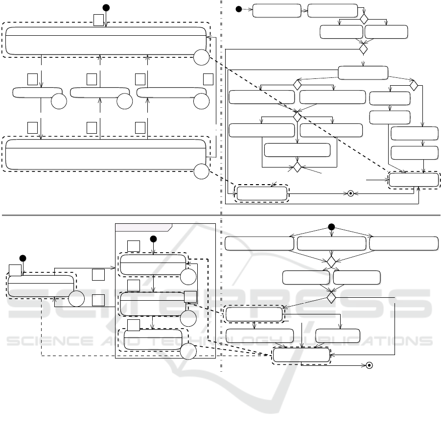
Figure 2 illustrates four pairwise integrated source
model artifacts, which represent the scope of investi-
gation on the automotive light control system. The
upper part of the figure shows the omni model parts
of the subsystem CtrlCrashFlashing (M1). The left
part determines the state chart specifying the subsys-
tem’s functionality, while the right part represents the
Towards Abstract Test Execution in Early Stages of Model-driven Software Development
219
System
Integration
Test
General-Purpose/
Domain-specific
Model
General-Purpose
Model
General-Purpose/
Domain-specific
Model
EGPP
Model
EGPP
Model
Integration
Model
M2MM2M M2M*
Test Case Generation
Test Report
Abstract Test Execution
Abstract
Test Cases
Figure 3: Processing pipeline for Abstract Test Execution.
test model. Further, this figure reduces the integra-
tion model elements to connectors between both sides
(dotted and dashed boxes and lines). For example, the
system model state CRASH FLASHING ACTIVE is con-
nected by the integration model to the test model ele-
ment cr CrashFlashing == 1. The same applies
to the lower part of Figure 2 addressing the Theft-
Flashing subsystem (M2). What both of the models
reveal is, that there is no need for a complete spec-
ification of mapping information in the integration
model, which is further detailed in Section 3.
3 THE ABSTRACT TEST
EXECUTION CONCEPT
Based on the orchestration of domain-specific mod-
els, we introduce the context for the Abstract Test
Execution (ATE) on the basis of Figure 3. The up-
per part revisits the split into domain-specific mod-
els and their transition to the internal representations
via M2M transformations. These M2M transforma-
tions are specified in QVTo with a focus on preserv-
ing the original mapping information across involved
domains as well as the included semantic of source
models. Based on the EGPP instance for the test do-
main, a set of abstract test cases is derived. The test
case generation is implemented by a dataflow analy-
sis on the test model, which is guided by structural as
well as dataflow oriented coverage metrics (Ammann
and Offutt, 2016). In this contribution, we applied the
bounded path-coverage criteria, realized by a specific
dataflow analysis, to maximize the set of abstract test
cases, evaluated by our ATE approach. The derived
abstract test cases complete the set of inputs for the
ATE processing pipeline. Herein, each test is chal-
lenged against the system model taking into account
the information specified in the integration model. At
System model
cr_CrashFlashing=0 [cf=0]
∅
cr_CrashFlashing=1 [cf=1]
cr_ImpactToggle=1 [it=1]
cr_ImpactToggle=0 [it=0]
cr_CrashFlashing==1 [cf==1]
Test model
cr_ImpactToggle && cr_ImpactX
[it && ix]
it=1 cf=0
it=0∅
cf=1 cf==1
it=1cf=0
∅it=0
cf=1 cf==1
!it && ixit && ix
it && ix !it && ix
it != 1
Merged Paths
!cr_ImpactToggle && cr_ImpactX
[!it && ix]
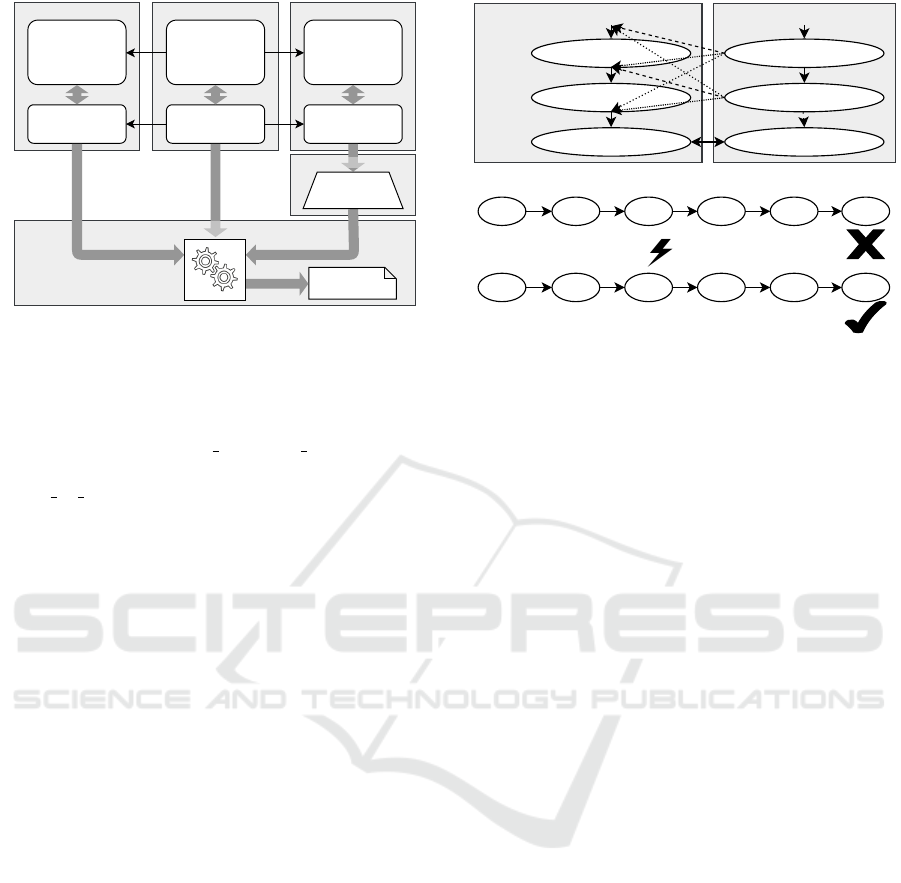
Figure 4: Running Example for ATE based on Figure 2.
the bottom of Figure 3 ATE’s test report, a purpose-
specific textual representation of the verdicts includ-
ing explanation, is conducted.
Before we elaborate the internals of ATE, we in-
troduce a running example. The running example (see
Figure 4) marks a compacted excerpt from M1 in-
troduced in Section 2.2. It is meant to illustrate the
core concepts applied during the dedicated steps of
the ATE. The affected paths of the system and test
model are shown in the upper part and the lower part
includes an intermediate analysis artifact further de-
tailed in Section 3.2. The statements in square brack-
ets represent a more compact version of the original
statements included and are used in the lower part
of the example. Further, the solid double arrow in-
dicates an integration model based mapping of con-
cepts, whereas the dotted and dashed arrows mark the
possibilities for merging paths during the ATE.
In general, the ATE is made up of three steps.
First of all the system model is prepared for the ATE.
Therefore, the affected sub models of the system
model will be detected and relevant start or end nodes
of the execution are determined.
Second, every test case will be verified. The sys-
tem model is not fully analyzed in one step, instead
it is split into its paths triggering separate analyses.
Finally, the results captured during the joint analysis
of an abstract test case and a system model path are
categorized as one of the four test verdicts to deter-
mine the quality-level of the afflicted model artifacts.
Three of those verdicts are based on the test verdict
set introduced by TTCN-3 (Grossmann et al., 2009).
A fourth test verdict is made up to state the abstract
computability of a test case (see Section 3.3).
MODELSWARD 2020 - 8th International Conference on Model-Driven Engineering and Software Development
220

3.1 Preprocessing
As previously described in Section 2.1.1, the inte-
gration model enables modelers to specify connec-
tions between elements of the system and test model.
Those connections are used to determine the start
node and possible end nodes for the verification pro-
cess of this test case. For example, the initial system
node of a test case execution is either explicitly spec-
ified by a linked model artifact of the respective sys-
tem model part, or implicitly determined by the initial
node of the system model part. The same holds for fi-
nal system nodes of a test case execution, which may
be specified explicitly. All the mapping information
given for intermediate model artifacts are processed
according to the merged paths rule set detailed in the
following section
Basically, a connection is relevant for the process,
if it includes a test model element of the test case un-
der analysis. Therefore, at least one relevant connec-
tion needs to be specified to validate the test case.
3.2 Abstract Test Case Verification
The first step of the abstract test case verification
(ATCV) is to integrate the test case into one of sev-
eral associated paths of the system model. Thereby,
each element of the test case is merged into paths of
the system model, with respect to the previously de-
termined start node and possible end nodes. These so
called merged paths are derived with regard to the fol-
lowing rules. First, the sequence of the elements of a
path is always retained. Second, test steps are always
inserted before guards of the system model. Third,
verification points are always added after guards of
the system model, if the associated verification point
is not connected to the integration model. Otherwise,
in consideration of rule two, the verification point is
inserted after the connected system node and subse-
quent guard if the affected transition is guarded.
In consideration of the running example, the
merging process is shown in Figure 4. There, a par-
tial path of the test model is merged into a sub path of
the system model by following the predefined rules.
The possible merge spots are accentuated by dotted
arrows. As a result, six valid merged paths exist.
It should be mentioned that the instructions of the
merged paths are compacted versions of the instruc-
tions of the test and system model, clarified by brack-
ets. In general, the combination of one test case and
one path of the system model can possibly result in
multiple merged paths as seen in Figure 4. We restrict
the number of generated merged paths to be consid-
ered in this case, since the sheer number of node com-
binations can easily explode. Please note that this re-
striction does not limit the merging of the test case
with other paths of the system model. For short, ev-
ery test case can be merged with several paths of the
system model, whereby every merging of two differ-
ent paths results in exactly one merged path. Thus,
the validation of one test case can take several merged
paths into account.
This lazy evaluation minimizes the workload, but
due to path restriction can lead to falsely unfulfill-
able test cases, as shown in Figure 4. To compen-
sate this, we allow the over-assignment of variables.
Thus, every variable can have multiple valid values.
In general, the system state is determined by vari-
ables introduced by modifying instructions contained
in the merged path. Modifying instructions modify
the value of a contained variable. In contrast, veri-
fying instructions evaluate the system state by com-
paring the set of variables with their expected values.
Due to over-assigned variables, multiple system states
can be valid at the same time, which solves the prob-
lem of falsely unfulfillable test cases.
In general, a merged path consists of instructions,
which modify or verify the system state. Overall,
modifying instructions alter the system state, whereas
verifying instructions check if a certain system state is
reached. The system model consists of guards, which
are verifying instructions and nodes, which possibly
contain modifying instructions. The test model holds
test steps and verification points. The former are able
to contain modifying instructions, whereas the latter
can hold verifying instructions.
When analyzing a merged path, guards are gener-
ally ignored during path exploration, but a fault is reg-
istered whenever a guard may not be evaluated posi-
tively, i.e. a guard may not be fulfilled. A fault is also
registered if a mapped end node can not be reached.
Another fault is the detection of an unknown variable
in an instruction. Whenever a variable is initialized
or updated, the new value is interpreted and then as-
signed to the identifier. The uninterpreted value is
able to contain variable identifiers and mathematical
or logical operators. All variable identifiers are re-
solved and their associated values are merged by us-
ing the operators. Whenever a variable identifier is
not resolvable, a fault is registered, except when a ver-
ification point contains an unknown variable then the
analysis of the merged path will be terminated and the
resulting report is not considered as result of the test
case. Therefore, we differentiate between the follow-
ing faults (F
x
):
(F
1
) A verification point is unfulfillable or challenged
with an over-assigned variable
(F
2
) A guard could not be fulfilled
Towards Abstract Test Execution in Early Stages of Model-driven Software Development
221

(F
3
) No end connection is specified
(F
4
) Unknown variable in test model
(F
5
) Unknown variable in system model
(F
6
) Guard contains time-dependent variable
(F
7
) Guard fulfilled by using over-assigned variable
An analysis of a merged path ends as soon as one
of the following conditions is fulfilled. These condi-
tions further guarantee that ATCV always terminates.
First, the maximum distance between two verifica-
tion points is limited to a certain threshold (default:
5 steps) to prevent deadlocks. Whenever this thresh-
old is exceeded, the verification of this merged path
is terminated. Furthermore, the analysis is also termi-
nated, if the end of the merged path is reached or the
last verification point is satisfied.
Whenever the analysis of a merged path is termi-
nated, a report is created. This report contains infor-
mation about the merged path, detected faults and as-
sociated priority group and is linked with the original
test case. Alongside the prescribed information, ev-
ery report is categorized as one of the four following
priority groups (P
x
):
(P
1
) All verifying instructions of the merged path are
fulfilled and the last verification point is fulfilled
with the instructions from one of the marked end
nodes
(P
2
) All verifying instructions of the merged path
are fulfilled and the last verification point is not
fulfilled with the instructions from one of the
marked end nodes
(P
3
) At least one verification point of the merged path
is unfulfillable, but a marked end node is found
(P
4
) At least one verification point of the merged path
is unfulfillable and no marked end node is found
The priority groups are needed to determine if the
entire merged path has been processed or only part
of it, due to premature termination. A report associ-
ated to priority group P
1
and P
2
indicates that the pro-
cessed merged path was entirely taken into account,
while P
3
and P
4
indicate a premature termination of
the verification process.
The prescribed faults and priority groups are used
to determine the representative result of the test case.
The report containing the highest detected priority
group and least registered number of unfulfilled ver-
ifying instructions marks the representative result of
the test case, which serves as the basis for the subse-
quent test verdict categorization.
Table 1: Test Case Result to Test Verdict Mapping.
F
1
F
2
F
3
F
4
F
5
P
3/4
F
6
F
7
P
1/2
V
4
• •
V
3
• • • •
V
2
• •
V
1
•
3.3 ATCV Result to Test Verdict
Mapping
In the last step, the representative results are mapped
to test verdicts. We differentiate between these four
verdicts (V
x
):
(V
1
) Passed
(V
2
) Probably Passed
(V
3
) Inconclusive
(V
4
) Failed
The test verdicts Passed, Inconclusive and Failed are
based on TTCN-3’s verdict set, extended by a new test
verdict Probably Passed. A test cases that is classified
as Passed fulfills all verifying instructions in their or-
der. As Probably Passed categorized test cases may
be able to fulfill the associated verification points, but
there is at least one verifying instruction which can
not be evaluated with the provided information of the
model. In this case, it is not possible to further detail
the model with the information needed. One can only
determine whether the test case can be fulfilled if the
actual program code is examined. A test case that is
classified as Inconclusive can not fulfill all verifying
instructions either. However, the model artifacts can
be enriched with the required information. A test case
categorized as Failed is not able to fulfill at least one
verifying instruction because a expected value is not
met.
As described in the definition of the test verdict
Probably Passed, the exact run-time of a program may
not be determined by the ATE. In order to avoid the
approximation of system states during test case verifi-
cation, we skipped this feature and left it over to code-
based testing mechanisms. In this context, the mod-
ification of time-dependent variables can not lead to
a result change, because these variables did not con-
tribute to the system state in the ATCV. That is why,
the related result may not be categorized as Passed,
but as Probably Passed.
Table 1 represents the mapping from faults and
priority groups to a test verdict. The test verdicts are
further weighted as follows: V
4
> V
3
> V
2
> V
1
. The
MODELSWARD 2020 - 8th International Conference on Model-Driven Engineering and Software Development
222
System model
cr_CrashFlashing=0 [cf=0]
∅
cr_CrashFlashing=1 [cf=1]
cr_ImpactToggle=1 [it=1]
cr_ImpactToggle=0 [it=0]
cr_CrashFlashing==0 [cf==0]
Test model
cr_ImpactToggle && cr_ImpactX
[it && ix]
it=0∅it=1cf=0 cf=1 cf==0
!it && ixit && ix cf != 0
rule-based Merged Path
!cr_ImpactToggle && cr_ImpactX
[!it && ix]
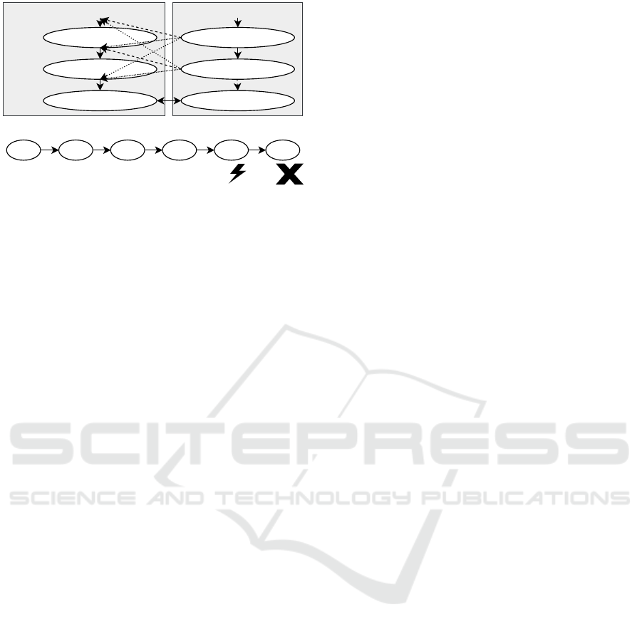
Figure 5: Example for a failing ATE based on Figure 2.
test verdict with the highest weight leads to the worst
possible outcome, whereas the test verdict with the
least weight leads to the best possible outcome. By
following a pessimistic approach of test verification,
the verdict with the highest weight is always priori-
tized. Thereby, a representative result is always cat-
egorized as the worst possible test verdict in consid-
eration of the detected faults and associated priority
group, as shown in Table 1.
In case of a representative result categorized as
Passed no faults were detected during the verification
of the respective merged path, consequently assigned
to the priority group P
1
or P
2
. Further, an incomplete
verification leads to a best case categorization as In-
conclusive, e.g. if the maximum allowed number of
exploration steps of the merged path is exceeded and
all verifying instructions are met at this point. The
combination of a representative result and its catego-
rization leads to the final report of the abstract test
case. These reports are bundled in a final stage repre-
senting the Test Report (see Figure 3).
Contrasting the happy case of tests being catego-
rized as Passed, Probably Passed, or Inconclusive,
Figure 5 shows a test case leading to a merged path,
which is categorized as Failed. Originated in an
ATCV fault of the F
1
category, which means a veri-
fication point could not be fulfilled by the dataset (cf
(0) != 0), the representative result of the test case is
consequently mapped to the Failed verdict.
All in all, the concept of ATE gives testers and
developers an indication about the quality-level of
model artifacts contributing to the development pro-
cess. In order to demonstrate the practical relevance
of the approach, a prototypical implementation has
been done. The implementation is based on a frame-
work, which was previously introduced by Pr
¨
oll et al.
(Pr
¨
oll et al., 2017), namely A3F. The analysis pipeline
shown in Figure 3 gives insight into the prototypical
realization.
4 PROOF OF CONCEPT
Based on the omni model of the case study introduced
in Section 2.2, we further do a proof of concept for
the ATE approach. Therefore, the processing pipeline
originally presented in Figure 3 is extended.
4.1 Analysis Pipeline for Proof of
Concept
The model artifacts from the three domains System,
Integration, and Test remain constant and again mark
the starting point (see Figure 6). Although the M2M
transformations are not included here, we like to point
out the importance for the flexibility of the ATE ap-
proach and for the validity of results produced by the
ATE. The EGPP-based system model is further con-
sumed by two separate ATE instances. While one in-
stance takes the original version of the system model,
the second instance processes a slightly modified ver-
sion, named EGPP model’. The modified version is
created in a controlled way, widely known as model
mutation in the context of fault-based testing (Morell,
1990).
In parallel, the respective test model is processed,
determined by mapping information of the integration
model. Here, the test case generation step derives a set
of abstract test cases, the second input for both of the
ATE instances.
Finally, both instances of the abstract test exe-
cution are performed, leading to a test report each.
Both artifacts, namely Test Report’ and Test Report,
are then compared based on the derived test verdicts.
Based on the assumption, that the extracted test cases
cover the system in a sense of edge coverage, every
manipulation of the system model should be chal-
lenged by at least one of the generated abstract test
cases.
For example, Figure 4 and 5 visualize the evalua-
tion of one particular test case on two different system
models as part of the previously presented analysis
pipeline. The system model shown in Figure 5 is a
altered version of the system model presented in Fig-
ure 4. Here, the constant of the model element E is
changed. This leads to a unfulfillable test case. This
particular case is part of the shift from unchanged to
V
4
categorized test cases, as summarized in Figure 7
(c) M1 E.
4.2 Analysis of Results
In general, one can distinguish between modifications
leading to structural or instruction-based changes of
Towards Abstract Test Execution in Early Stages of Model-driven Software Development
223

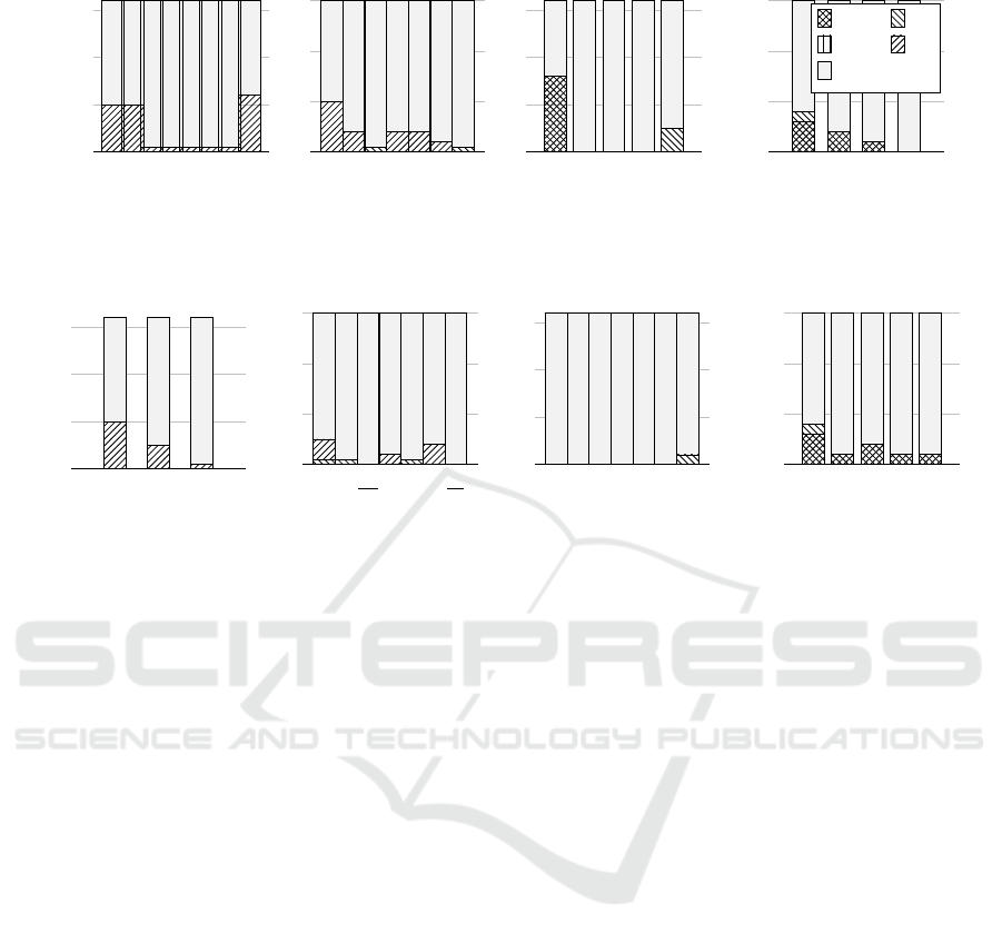
the original system model. Figure 7 shows all the re-
sults produced during the ATE of the previously in-
troduced models M1 and M2 including labels anno-
tated to elements of these models, specified in Fig-
ure 2. In our evaluation, structural modifications, like
the deletion (7a) or insertion (7b) of edges, as well as
instruction-based modifications, like the replacement
of instruction constants (7c) or exchange of guards
with true (7d) are taken into account.
The mentioned modifications were consequently
applied to appropriate model elements of Figure 2.
One pillar of the figure represents a run of the previ-
ously introduced analysis pipeline, which means the
height is determined by the number of test cases gen-
erated during the pipeline execution. Thereby, the
model mutation modifies exactly one model element
of the original system model. In general, every mod-
ification aims at exactly one element of the system
model, except for the edge insertion case, which inte-
grates new edges into the original system model. All
permutations are taken into account, but only the most
significant impacting edge is represented.
Furthermore, we observed that some modifica-
tions did not trigger any change of the resulting test
verdict. We identified two reasons for that. First, there
are cases which can not lead to a result change, which
is due to the structural characteristics of the models
M1 and M2. This holds for the modifications of B, C,
D and D
0
shown in Figure 7b, as well as the modifi-
cations of 1 to 6 shown in Figure 7d. Second, the re-
placement of a constant of element C
0
and 6
0
also did
not lead to a result change which is shown in Figure 7c
(target modifications underlined). The reason is given
by the variable t which represents a time-related vari-
able, which is not taken into account by ATE.
All in all, we showed that a modification of the
system model in most cases leads to a change of the
assigned test verdicts. Therefore, the prototypical im-
plementation is able to abstractly evaluate test cases
with the limitation that time-dependent variables are
ignored and in the best case, such test cases are clas-
sified as Probably Passed.
5 RELATED WORK
Our concept focuses on providing a flexible semi-
formal model-based testing approach that is designed
for early stages of software development. In general,
MBT aims at generating test cases and executing them
on the SUT. Behavioral models are used to automati-
cally derive test cases that check whether a system is
performing certain intended behaviors correctly. Tra-
ditionally, these test cases are executed on the SUT in
System Integration Test
EGPP
Model
Integration
Model
Path Extraction
Abstract
Test Cases
Abstract Test Execution
Test
Report
Test
Report'
EGPP
Model'
Model Mutation
EGPP
Model
Figure 6: Analysis pipeline for the evaluation of abstract
test execution within the framework.
a classical black box testing manner. (Apfelbaum and
Doyle, 1997)
In contrast, our approach may be seen as a gray
box testing technique as previously presented by
Khan et al. (Khan et al., 2012). Therefore, we can
not only distinguish if a test case fails, but also where
the challenged test case fails.
Model checking is another approach for model
validation. In contrast to our concept, the validation
process commonly based on formalized requirements,
which are compared with every possible system state
of the SUT (Baier and Katoen, 2008). Whereas, we
follow a semi-formal and data-flow-oriented way of
modeling, and comparing requirements with the SUT.
Moreover, model checkers are preferably applied in
later stages of development. Our approach meant to
be applied in early stages of development as described
in (Pr
¨
oll and Bauer, 2018b).
Another approach dealing with the formal execu-
tion of model artifacts is represented by the OMG
specification Semantics of a Foundational Subset for
Executable UML Models (fUML) (OMG, 2018). Our
approach shares the same basic concept of model ex-
ecution as fUML, as demonstrated by Guermazi et al.
(Guermazi et al., 2015). Further, both approaches are
not generating program code, instead the model is di-
rectly interpreted most likely like script engines inter-
pret scripts. While fUML is based on and limited to
a subset of UML, our approach can easily be adapted
to support other domain-specific modeling languages,
like SysML.
A more general approach for simulation-based
validation of development artifacts is given by x-in-
the-loop approaches. This concept has its origins in
the engineering sector (Plummer, 2006). For exam-
ple, MiL (Model-in-the-loop) testing is used to eval-
uate the behavior of a mechanical system by a simu-
lation based on mathematical descriptions, where the
SUT is represented by a model. Another variant is
given by Sil (Software-in-the-loop), where the simu-
lation is based on compiled artifacts of the system, as
MODELSWARD 2020 - 8th International Conference on Model-Driven Engineering and Software Development
224
843
5
21
6
7
0
10
20
30
Deleted edge
Change of test verdict
M1
1’ 2’ 3’ 4’ 5’ 6’ 7’
0
20
40
60
Deleted edge
M2
(a) ... edge deletion.
A B
C
D E
0
10
20
30
Start node of inserted edge
M1
A’ B’ C’ D’
0
20
40
60
Start node of inserted edge
M2
V
1
V
2
V
3
V
4
Unchanged
(b) ... node insertion.
A E 7
0
10
20
30
Affected model element
Change of test verdict
M1
A’B’C’D’ 3’ 2’ 6’
0
20
40
60
Affected model element
M2
(c) ... constant replacement.
43
5
21
6
7
0
10
20
30
Replaced instruction of edge
M1
2’ 3’ 5’ 6’ 7’
0
20
40
60
Replaced instruction of edge
M2
(d) ... instruction replacement.
Figure 7: Results of ...
e.g. demonstrated in (Demers et al., 2007). Today,
MiL simulations are often part of the design process
of embedded systems. In terms of tooling, these sim-
ulations are mostly created with Simulink (Khalesi
et al., 2019) or MatLab (Gambarotta et al., 2019),
two well known engineering tools. In the context of
testing, the mentioned simulation approaches show
a black box characteristic. In contrast to that, our
concept involves continuous monitoring of the system
state, therefore categorized as a gray box technique.
6 CONCLUSION AND FUTURE
WORK
In this paper, we have presented a valuable approach
tackling the twofold challenge, namely the steadily
raising level of software complexity along with the
insights on cost and time intensity of fixing induced
faults. Therefore, we establish a basic approach to-
wards a real shift left of V & V efforts. Based on a
varying set of domain-specific models, an integrated
model basis is build. A subsequent dataflow-based
analysis of the involved test and system related mod-
els, driven by a set of extracted abstract test cases, en-
ables developers to draw conclusions about the con-
formance of specified and intended functionalities of
the system. To underline the abstract computability of
test cases, a new test verdict was introduced.
Due to merging of test steps into a system path,
the number of merged paths can easily explode. We
addressed this problem by reducing the quantity of all
possible merged paths to one, thereby allowing the
over-assignment of variables under certain circum-
stances.
As the research successfully demonstrated, we see
future work in a better formalization adressing the po-
tential for semantic gaps originated in the M2M trans-
formations, as well as in technical improvements of
the prototypical implementation, but also in the in-
tegration and adaption to other application contexts.
The technical improvements may include the devel-
opment of more sophisticated preprocessing steps,
leading to a better scalability and an optimized mem-
ory footprint. Moreover, the use of heuristic ap-
proaches for picking the most relevant system path
during ATE may also represent a valuable extension
of the current work. Focusing possible new appli-
cation contexts, our approach could play a central
role in a model-centric realization of mutation testing.
Herein, a scalable mechanism for abstract test execu-
tion probably has the potential to push the acceptance
of such technologies to the next level. Further, we
see another application scenario of our approach in
the area of semi-automated modeling support. There-
fore, the results gained from the abstract test execu-
tion may be used as a knowledge base for a dynamic
Towards Abstract Test Execution in Early Stages of Model-driven Software Development
225

and aligned set of modeling guidelines, addressing the
weakness of vague guidelines due to missing context
information.
ACKNOWLEDGEMENTS
The research in this paper was funded by the Ger-
man Federal Ministry for Economic Affairs and En-
ergy under the Central Innovation Program for SMEs
(ZIM), grant number 16KN044137.
REFERENCES
Ammann, P. and Offutt, J. (2016). Introduction to software
testing. Cambridge University Press.
Apfelbaum, L. and Doyle, J. (1997). Model based testing.
In Software Quality Week Conference, pages 296–300.
Baier, C. and Katoen, J.-P. (2008). Principles of model
checking. MIT press.
Demers, S., Gopalakrishnan, P., and Kant, L. (2007). A
generic solution to software-in-the-loop. In MIL-
COM 2007-IEEE Military Communications Confer-
ence, pages 1–6. IEEE.
Galin, D. (2004). Software quality assurance: from theory
to implementation. Pearson Education India.
Gambarotta, A., Morini, M., and Saletti, C. (2019). De-
velopment of a model-based predictive controller
for a heat distribution network. Energy Procedia,
158:2896–2901.
Grossmann, J., Serbanescu, D. A., and Schieferdecker, I.
(2009). Testing embedded real time systems with ttcn-
3. In ICST, pages 81–90. IEEE Computer Society.
Guermazi, S., Tatibouet, J., Cuccuru, A., Dhouib, S.,
G
´
erard, S., and Seidewitz, E. (2015). Executable mod-
eling with fuml and alf in papyrus: tooling and exper-
iments. strategies, 11:12.
Jones, C. (2008). Applied Software Measurement: Global
Analysis of Productivity and Quality. McGraw-Hill
Education Group, 3rd edition.
Khalesi, M. H., Salarieh, H., and Foumani, M. S. (2019).
Dynamic modeling, control system design and mil–hil
tests of an unmanned rotorcraft using novel low-cost
flight control system. Iranian Journal of Science and
Technology, Transactions of Mechanical Engineering,
pages 1–20.
Khan, M. E., Khan, F., et al. (2012). A comparative study of
white box, black box and grey box testing techniques.
Int. J. Adv. Comput. Sci. Appl, 3(6).
Morell, L. J. (1990). A theory of fault-based testing. IEEE
Transactions on Software Engineering, 16(8):844–
857.
Object Management Group (OMG) (2004). Uml 2.0 testing
profile specification.
OMG (2002). Meta object facility specification.
OMG (2011). OMG Unified Modeling Language (OMG
UML), Superstructure, Version 2.4.1.
OMG (2018). About the semantics of a foundational subset
for executable uml models specification version 1.4.
Peleska, J., Honisch, A., Lapschies, F., L
¨
oding, H., Schmid,
H., Smuda, P., Vorobev, E., and Zahlten, C. (2011).
A real-world benchmark model for testing concur-
rent real-time systems in the automotive domain. In
IFIP International Conference on Testing Software
and Systems, pages 146–161. Springer.
Planning, S. (2002). The economic impacts of inadequate
infrastructure for software testing. National Institute
of Standards and Technology.
Plummer, A. R. (2006). Model-in-the-loop testing. Pro-
ceedings of the Institution of Mechanical Engineers,
Part I: Journal of Systems and Control Engineering,
220(3):183–199.
Pretschner, A. and Philipps, J. (2005). 10 methodological
issues in model-based testing. In Model-based testing
of reactive systems, pages 281–291. Springer.
Pr
¨
oll, R. and Bauer, B. (2018a). A model-based test case
management approach for integrated sets of domain-
specific models. In 2018 IEEE International Confer-
ence on Software Testing, Verification and Validation
Workshops (ICSTW), pages 175–184.
Pr
¨
oll, R. and Bauer, B. (2018b). Toward a Consis-
tent and Strictly Model-Based Interpretation of the
ISO/IEC/IEEE 29119 for Early Testing Activities.
In Proceedings of the 6th International Conference
on Model-Driven Engineering and Software Develop-
ment - Volume 1: AMARETTO, pages 699–706. IN-
STICC, SciTePress.
Pr
¨
oll, R., Rumpold, A., and Bauer, B. (2017). Applying in-
tegrated domain-specific modeling for multi-concerns
development of complex systems. In International
Conference on Model-Driven Engineering and Soft-
ware Development, pages 247–271. Springer.
MODELSWARD 2020 - 8th International Conference on Model-Driven Engineering and Software Development
226
