
Real Models are Really on M0 - Or How to Make Programmers
Use Modeling
Joachim Fischer
1 a
, Birger Møller-Pedersen
2 b
and Andreas Prinz
3 c
1
Department of Computer Science, Humboldt University, Berlin, Germany
2
Department of Informatics, University of Oslo, Oslo, Norway
3
Department of ICT, University of Agder, Grimstad, Norway
Keywords:
Model, System, Language, Ontological Modeling.
Abstract:
This paper discusses the term ’model’ and the role of the level M0 in the four-layer metamodeling architecture
of MOF/OMG. It illustrates the failures of the OMG MOF standard and how a model is an abstraction, not a
description. We apply two simple approaches: (1) observing the use of models (of real or planned systems) in
system development, including prototyping, simulations, and models in general, and (2) comparing modeling
with programming. These approaches lead to the conclusion that models should be placed on M0, while UML
models are model descriptions. This conclusion leads to a better understanding of InstanceSpecification for
description of snapshots, and of metamodeling applied to ontologies.
1 INTRODUCTION
Modeling and programming communities are diverg-
ing, each developing their own languages and tools
1
.
Programmers mainly focus on (program) execu-
tions, while modellers handle different kinds of what
in the modeling community are called models (do-
main models, requirements and design models) in a
mixture of diagrams and text. Programmers are to
a certain extent also modeling, but in order to have
programmers apply modeling for real, (and to have
modellers also focus on executions), there has to be a
shared understanding of what models are.
The notions of models and metamodels from the
(UML) modeling community do not help. As long as
the four-levels OMG/MOF architecture (OMG, 2016)
with the levels M0 to M3 has existed, the role of
M0 has been discussed, questioned, misunderstood,
or even ignored (Atkinson and K
¨
uhne, 2003; B
´
ezivin
and Gerb
´
e, 2001; Eriksson et al., 2013; Favre, 2004).
In this paper, we will contribute to a shared under-
a
https://orcid.org/0000-0003-2476-3996
b
https://orcid.org/0000-0003-2123-3260
c
https://orcid.org/0000-0002-0646-2877
1
Domain-specific languages (DSL) (Fowler, 2005) and
Problem Solving Environments (PSE) (Kawata, 2015) are
approaches that bring modeling and programming together
in specific domains.
standing by looking at the use of models in systems
development, thereby giving the right role to models.
The ultimate goal of systems development is to
produce systems, i.e. changing sets of executing ob-
jects that interact with each other and with entities in
the environment of the systems. Systems are made
using various kinds of descriptions, ultimately pro-
grams from which executions with objects (on level
M0) are created. Similarly, execution of Executable
UML(OMG, 2018) models will generate a structure
of objects at M0. That is, Executable UML models
are also descriptions (prescriptions) of executions.
We will also look at the general notion of model. It
is generally agreed that a model is an abstraction of an
existing or planned system. A model is made from a
perspective and has a purpose. Therefore, only a sub-
set of the properties of a system are represented in the
model. It is possible to experiment with the models in-
stead of with the real systems and deduce properties
– for good reasons, it is not possible to experiment
with planned systems. This idea of model is indepen-
dent of the model being material or mathematical or
digital. In programming (and in modeling with Exe-
cutable UML), experiments are not experiments with
the prescriptions, but experiments are done with the
executions (the systems).
The arguments above indicate that models are at
M0, while descriptions and prescriptions are on lev-
Fischer, J., Møller-Pedersen, B. and Prinz, A.
Real Models are Really on M0 - Or How to Make Programmers Use Modeling.
DOI: 10.5220/0008928403070318
In Proceedings of the 8th International Conference on Model-Driven Engineering and Software Development (MODELSWARD 2020), pages 307-318
ISBN: 978-989-758-400-8; ISSN: 2184-4348
Copyright
c
2022 by SCITEPRESS – Science and Technology Publications, Lda. All rights reserved
307

els M1-M3. We are aware that this is different from
the common terminology, where descriptions and pre-
scriptions on M1 are called (UML) models. However,
placing models on M0 matches how programmers and
system developers think about models, and it matches
the everyday use of the term model.
In(Madsen and Møller-Pedersen, 2018), the au-
thors have made the same argument, i.e. that program
executions are models. We will apply this understand-
ing to the MOF architecture, which is not addressed
in (Madsen and Møller-Pedersen, 2018).
The (UML) modeling community has different
opinions on M0: (K
¨
uhne, 2006) has the reality to be
modeled there, while UML in 2011 (OMG, 2011) had
InstanceSpecifications there. The understanding
of having models at M0 provides a better understand-
ing of UML InstanceSpecification, metamodel-
ing, and domain modeling, including ontologies.
The paper is structured as follows. In Section 2,
we discuss the role of models in systems develop-
ment, including the general understanding of the con-
cept ’model’. Section 3 compares modeling and pro-
gramming. Section 4 covers different understandings
of InstanceSpecification, including its basis for
ontological metamodeling, followed by a review of
existing understandings of M0 in Section 5. Finally,
we summarize in Section 6.
2 SYSTEM DEVELOPMENT
System and System Description
Systems development produces systems that fulfil a
given purpose and provide required functionalities.
For this paper, we assume that system development
uses object-oriented programming and modeling.
Definition 1 (System). A system is a changing set of
executing objects that interact with each other and
with entities in the environment of the system. Objects
may be existing entities like devices, and they may be
entities that have to be made as part of the systems
development. This way, a system is a set of possible
executions, i.e. a set of object configurations that exist
at different time points.
Systems are made using various kinds of system
descriptions from which these executing objects are
created, see the left side of Figure 1.
Among these kinds of descriptions, programs are
prescriptions of systems as possible program execu-
tions. A program execution will consist of a changing
structure of objects according to the prescriptions of
objects and classes in the program, and these objects
Figure 1: Description and Prescription, adapted from (Fis-
cher et al., 2016).
will obviously be on M0 and thereby the systems are
at M0.
For Executable UML (OMG, 2018) the situation is
the same: Executable UML model execution will gen-
erate a structure of objects on M0. That is, Executable
UML models are really prescriptions of executions.
Definition 2 (Model). A model is a system that is in
the model-of relationship to a referent system, existing
or planned.
Note that both physical and mathematical models
are systems, because it is their behaviour (their execu-
tions) that makes them models. Scale models are also
concrete representations, but typically with the same
object structure that does not change over time.
As can be seen in Figure 1, a system description
always leads to a system, which is a set of possible
executions. The system does not need to be a model
if there is no related referent system.
Figure 1 is based upon the system and model con-
cepts from the language DELTA
2
((Holbæk-Hanssen
et al., 1973)) placed in the context of the MOF four-
layer architecture. Note that the system (the execution
of the system description) is at M0, whereas the ref-
erent system (the system to be modeled) is not part
of this architecture. Still, it is placed at the level of
M0 to indicate that this is an existing or planned real
system, not a description.
A UML model is not a model according to this
definition of model, but rather a model description.
We will use the term ’UML model’ to denote model
descriptions expressed in UML.
Experiments with systems, like testing and simu-
lations, are experiments with an execution, not with
descriptions. Validation is the process of finding out
whether a system has the right model-of relation to an
existing or planned real system, i.e. whether their exe-
cutions match. Even for review, it may be interesting
to compare, e.g. required sequence diagrams with the
2
DELTA was a very early (1973) modeling language, at
that time called ’system description language’.
MODELSWARD 2020 - 8th International Conference on Model-Driven Engineering and Software Development
308

sequence diagrams of the system (for a given func-
tionality), as reported in (Daun et al., 2019), where
the generated sequence diagrams are called ’review
models’.
Another kind of experiment is prototyping. In
(Exner et al., 2014), it is well documented that proto-
typing is experimenting with systems in varying de-
grees of completeness, not experimenting with de-
scriptions. Validation by prototyping is the process
of finding the system that is the desired model of a
planned system.
Modeling in Systems Development
In system development with modeling languages, a
system description will typically be a graphical de-
scription of a planned system combining new ele-
ments with existing (real) elements. The example
in Figure 2 of a temperature controlling system ex-
emplifies this. It describes a class of systems con-
sisting of existing (white) elements like Heating and
Cooling actuators, and a Temperature sensor; the
(grey) Controller is the one to be made so that it fits
into this architecture.
Figure 2: UML diagram that describes a temperature con-
trolling system (from (Fischer et al., 2016)).
Note that Figure 2 is not a picture of a class of
systems, but a UML description of a composite class
with parts and connectors.
Sensors and actuators model the real sensors and
actuators. A simulation will simulate the Room, the
sensors and the actuators, while the Controller will
be tested or experimented with. In this process,
the description of the Controller will probably be
changed according to the simulations. However, it is
still the running Controller that is the model of the
controller to be in a building when it is deployed.
Programming in Systems Development
If only programming languages are exploited in sys-
tem development, the situation is the same. Some
class descriptions are descriptions of concepts from
the application domain (like real passengers, flights,
seats, tickets), and objects of these classes model the
corresponding passengers, flights, seats etc. Other
class descriptions are descriptions of elements of the
planned system (e.g. elements of the planned reser-
vation system). Few programming languages support
the kind of description in Figure 2. However, there is
no fundamental reason for not being able to express
this in programming languages, see, e.g. (Aldrich
et al., 2002).
When it comes to systems as introduced in Figure
1, programmers do not doubt that they are part of sys-
tem development (which of course includes more than
programming) where the goal is to produce systems
by making programs that are executed by computers.
For Executable UML the experiments will also
be with executions, not with diagrams, so real Ex-
ecutable UML systems really reside on level M0.
There is no difference between program executions
and executions for Executable UML, except for the
different abstraction levels of the language mecha-
nisms. For Executable UML the artefacts at M1 are
therefore descriptions of systems.
What then about the parts of UML that are not
covered by Executable UML, e.g. interactions and
use cases, and that are still used in system develop-
ment? They both reside at M1. Use cases are typ-
ically used as prescriptions of required functionality
of the system, while interactions may be used as both
prescriptions of required behaviour (or undesired be-
haviour) and descriptions of what happens with a sys-
tem. So they are not models, according to the defini-
tion of model above. As mentioned above, in general,
a UML model on M1 is a system description, or more
precisely a description of a system that is a model of
a referent system.
Models in General
The following definition of model in general sum-
marizes definitions from Webster, Collins, Wikipedia,
(Bossel, 2013), and a general understanding of model.
A model is a small or large, abstract or ac-
tual, representation of a planned or existing
entity or system from a particular viewpoint
and with a specific purpose.
Observe that this definition of model always de-
fines a relationship between the system acting as the
model, and the system being modeled, see also Figure
1 and Definition 2.
Mathematical models are examples of abstract
representations. A mathematical model is usually a
Real Models are Really on M0 - Or How to Make Programmers Use Modeling
309

set of equations describing properties of a given sys-
tem, e.g. in the form of differential equations.
Libraries are systems with changing sets of books
and loans. Models of libraries with the purpose to un-
derstand libraries or to make computer-based library
systems must be systems of objects representing real
books and loans. The model, in this case, is an actual
representation. Similarly, the model of the tempera-
ture controlling system in Figure 2 is an actual repre-
sentation: it contains sensors and actuators that model
the real sensors and actuators that are part of the real
building when the Controller is deployed.
In (Madsen and Møller-Pedersen, 2018), the fol-
lowing illustrative example of a model as an actual
representation is used. Consider the Mini in Figure 3.
Figure 3: Mini.
What is the model of the Mini: the Lego car to the
right in Figure 4 or the description of how to build it to
the left in Figure 4? Any child will answer ’the Lego
car’. Even grown-up people (they have been children
too) will answer that the Lego car is the model of the
real car.
Figure 4: Description and Model.
This example also illustrates the notion of inter-
acting or experimenting with a model. A kid playing
with the Lego car to imitate driving interacts with the
model (the Lego car), its different states, like posi-
tion, orientation, and velocity, while imitating how a
car turns around. In case the Lego car has no engine
and no steering control, playing with it simulates the
execution. In case of a machine and steering capa-
bilities, the kid will control the execution at crucial
points, like changing orientation and speed. In case
of a more elaborate Lego car (or even a Lego robot)
that is prescribed to follow a given route and avoid ob-
stacles, kids will experiment with the running model
car by, e.g. placing or moving obstacles.
Some people get the chance to be trained as pi-
lots in flight simulators. Flight simulators are models
of real flights, and the pilots interact (maybe also ex-
perimenting) with the program execution (and some
specialised hardware), not with the program that im-
plements the simulator. Had it been done entirely in
Executable UML, then the pilots would interact with
the execution on level M0, not with the descriptions at
M1. Descriptions of classes, state machines and ac-
tivities as part of Executable UML are model descrip-
tions, while the executions are models for interaction
and experimentation.
3 MODELING AND
PROGRAMMING
Metamodels and Grammars
It is established that Figure 5 gives the correspon-
dence between the definition of modeling and pro-
gramming languages, see, e.g. (Butting et al., 2018)
and (B
´
ezivin and Gerb
´
e, 2001).
M3 meta-metamodel EBNF
M2 metamodel grammar
M1 (UML) model program
M0 model execution program execution
Figure 5: Metamodels and Grammars.
This correspondence is obvious, provided that the
modeling language is executable, like, e.g. Exe-
cutable UML. However, even for UML in general this
is the case: objects of classes defined in UML at M1
reside at M0.
However, metamodels and grammars are not com-
pletely the same. Metamodels describe abstract syn-
tax (structure) of a language only and their concrete
syntax usually is defined using editors. Grammars
define the concrete syntax, and parsers generate ab-
stract syntax trees from concrete syntax. Metamodels
may include links, e.g. from the use of a concept to
the definition of the concept. Parsers use attributes
in the objects of the abstract syntax trees instead of
such links. Even with the apparent correspondence
between metamodels and grammars, the switch be-
tween them requires some effort, see again (Butting
et al., 2018).
Programs and UML Models
A program (on M1) is a prescription of a number of
possible program executions. A program execution
MODELSWARD 2020 - 8th International Conference on Model-Driven Engineering and Software Development
310

will consist of a changing structure of objects accord-
ing to the prescriptions of objects and classes in the
program, and these objects will be on M0. Objects
behave according to their prescription of behaviour as
part of the program at M1.
As mentioned above, some objects, like passen-
ger objects in a reservation system, will model the
corresponding real passengers. Properties (like name
and address) and capabilities (like changing address)
of the passengers will be reflected by corresponding
properties of the objects that model the passengers.
A similar approach should be taken for executable
modeling languages, and for modeling languages in
general. As an example: Executable UML model ex-
ecution will generate a structure of objects according
to the prescriptions of Executable UML classes at M1,
and these objects will be on M0. Objects behave ac-
cording to their prescription of behaviour as part of
the Executable UML model at M1, i.e. Executable
UML models are prescriptions of executions.
This approach divides the world into descrip-
tions/prescriptions and objects, as shown in Figure 6.
M3
Descriptions and prescriptions, in terms of
diagrams, text, or combined
M2
M1
M0
Objects, with behaviours, states and
links between objects
Figure 6: Descriptions and objects.
Below the line, there are objects, there are states of
objects, and there are state changes resulting from the
behaviour of the objects. Objects model phenomena
in the application domain.
Above the line, there are no objects, there are no
states, and there are no state changes. However, there
are prescriptions of objects (singular or by means of
classes), there are prescriptions of states (e.g. descrip-
tions of attributes of objects), and there are prescrip-
tions of state changes, e.g. assignments and behaviour
prescriptions in general.
In the following, we will use the term description
for both description and prescription, except in cases
where it is essential to distinguish. The main differ-
ence is between objects (at M0) and descriptions of
objects (at M1-M3).
Compared with M0, not only M1 but also M2 and
M3 contain descriptions. The fact that M1 and M2
have objects of metaclasses at the level above does
not change this. These objects are there just for rep-
resenting descriptions, just like a structure of linked
objects represents programs in the form of abstract
syntax trees. These objects are handled by tools (e.g.
editors) that manipulate descriptions; they are not ob-
jects being parts of executions.
Programmers and Modeling?
How does the idea of model presented here relate to
programmers, who more often than not live by the slo-
gan ’Real programmers do not model’? They argue
that making separate descriptions of what they can do
in their favourite programming language is a waste
of time. Besides, such descriptions often become ob-
solete because of inadequate tools with no two-way
transformations.
However, programmers do model, but not in mod-
eling languages. Programming involves modeling be-
cause application domain concepts are identified and
represented by classes with properties that are given
by the purpose of the system being developed. Ob-
jects of these classes model the corresponding phe-
nomena. If the domain is library systems, there will
be books, in programs described by a class Book and
with Book objects being models of the real books, see
Figure 7 for the situation with UML and Java. Start-
ing with a UML class book, the Java class is generated
from a class description in UML. However, this does
not make the UML description a model of the Java
code; a model has to be a system, not just a descrip-
tion. Similarly, in a reservation system, there will be
Figure 7: UML and Java class at M1, objects at M0 model-
ing the real book.
Passenger and Flight objects that model the corre-
sponding real passengers and flights.
It is important to emphasize that the UML class
Book is not a model of the Java class Book. Instead,
both of them are prescriptions of objects that are mod-
els of the real books.
This way, a shared understanding of models and
modeling can (in addition to better tool support) help
programmers use modeling. A programmer would
not call the program (Figure 5) a model, as the pro-
gram is ’just’ a prescription. The ultimate goal is
the program execution. As illustrated above, the pro-
gram executions (library system, reservation system)
will have objects that model the corresponding ele-
ments from the application domain and even from re-
ality. So, for programmers, the models are on M0.
Of course, a program execution contains elements
Real Models are Really on M0 - Or How to Make Programmers Use Modeling
311

that are there just to have the execution on a specific
platform or because of the implementation technique
used. Some of these elements are simply platform- or
implementation specific. However, there may also be
elements that are modeled according to some techni-
cal domain, like, e.g. communication using a specific
protocol.
Semantics and Meaning
There is a strong connection between level M0 and the
semantics of a modeling or a programming language.
Moreover, there is a relation that relates the model
with the real referent system it models, which we have
called model-of.
Let us look into semantics. Any formal language
provides a semantics detailing the transition from a
(system) description into a system. In the metamod-
eling architecture, this is the move from descriptions
on levels M1-M3 to objects and executions on level
M0. Therefore, (formal) semantics is a relation, and it
is vertical (crossing levels). The level crossing might
not happen in the first step, as, e.g. with translational
or denotational semantics. However, someplace down
the line, the description has to come to life, crossing
the level. We generalize the idea of semantics as fol-
lows.
Definition 3 (Semantics). Semantics is the relation
between a (system) description and its prescribed
possible executions (the system)
3
. Sometimes, the de-
scribe relationship can be considered semantics.
It is important to note that the language defines
the semantics - in fact, this is the only aspect of the
language crossing the level boundaries. So the lan-
guage description on level M2 details the transition
of a description on level M1 into a system on level
M0. The user is then free to create descriptions on
M1 in the language, which will be turned into execu-
tions (systems) on M0 by way of the semantics. This
way, semantics is defining linguistic instantiation as
defined in (K
¨
uhne, 2006). Moreover, it also defines
the semantics of ontological instantiation in case the
language provides it (see Section 4 for more details).
The model-of relation is different from semantics.
There can be many models of the same system. Even
though the real systems are outside the metamodeling
architecture, they are at the same level as the execu-
tions in the architecture, which reside at M0. So it is
most meaningful to consider the real referent systems
3
The DELTA language report used the neutral term
’generator’ that generates a system based upon a system
description. A generator could be a machine or a human
being, or a mixture.
on level M0 as well. This way, the model-of relation
is horizontal, informal and connected to abstraction.
Behaviour Descriptions for Metaclasses
With the above understanding of models as systems
on level M0, and with just descriptions at M1, what
is then the understanding of metamodels at M2? M1
contains descriptions of objects at M0. The descrip-
tions are represented by objects (of classes at M2), so
M2 similarly contains descriptions. In relation to M1,
they are descriptions, while in relation to M0, they are
meta-descriptions.
Metamodeling allows defining abstract syntax for
languages, and the levels M1 to M3 express this well.
As we shall see below, modeling ontologies is not
metamodeling (Aßmann et al., 2006). Languages for
modeling ontologies, like OWL (W3C, 2012), may,
however, be defined by metamodels. OMG has, in
fact, defined the language ODM (OMG, 2014) for
defining ontologies.
Definition 4 (Metamodel). A metamodel is a descrip-
tion of a language. The corresponding executions be-
long to an implementation of the language, i.e. an
IDE. The relation between a metamodel on M2 and
its execution on M1 is the same as the relation be-
tween descriptions on M1 and models on M0, namely
semantics.
The narrow definition of metamodel in OMG
would only allow structural definitions of languages.
However, there could also be behaviour descriptions
as part of metaclasses, e.g. metaclass Class. Such
behaviour would not be M0-behaviour common to
all instances of all classes of the metaclass Class.
Two classes A and B, both represented by objects of
the metaclass Class, would not get the behaviour of
metaclass Class. Instead, as objects of metaclasses
are instances that represent descriptions, then opera-
tions on these objects would typically change the ob-
jects, and thereby the description represented by these
objects. This could, e.g. be operations to be used in
refactoring of descriptions.
Such behaviour is executed on the level M1, i.e.
with tools handling descriptions. The most obvious
tools here would be editors and IDEs, with functional-
ity for changing descriptions. In this case, the descrip-
tions on level M1 would be changing, such that the
description that is executed here would be the meta-
model on M2, which is a model of the language ex-
ecution (the editor or the IDE). The same thought is
used in language workbenches (Fowler, 2005).
MODELSWARD 2020 - 8th International Conference on Model-Driven Engineering and Software Development
312
4 UNDERSTANDING
INSTANCESPECIFICATIONS
InstanceSpecifications as Snapshots
We have established a distinction between the world
of descriptions and the world of systems of objects,
see figure 6. For programming and for Executable
UML, the objects will be elements of executions (sys-
tems), and as such, they do not belong to the de-
scription stack of M1-M3. These systems at M0 are
created using prescriptions. Most often, they should
model a referent system. In case an execution does
not match the corresponding execution in the referent
system, the usual way is to use some debugging tool
to provide descriptions (snapshots) of objects as they
are at a particular stage of execution.
Definition 5 (Snapshot). A snapshot is a description
of the current state of execution. This way, a snapshot
relates to an execution semantics and has to be able
to represent all instances existing at runtime
4
.
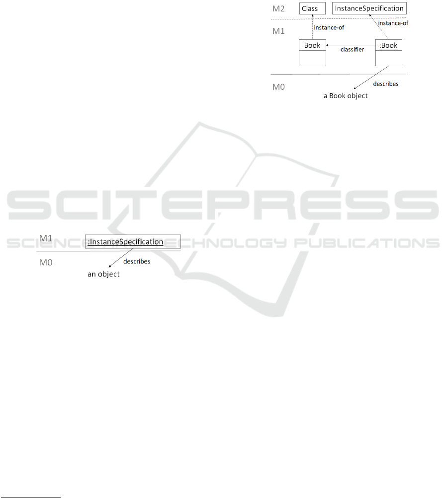
UML provides InstanceSpecifications for
expressing snapshots, see Figure 8. An Instance-
Specification will have a slot for each of the
features of the object, describing the current value
of the feature. InstanceSpecifications are de-
Figure 8: Instance Specification.
scriptions at M1 for describing objects at M0. An
InstanceSpecification may, however, also be
used to prescribe objects, see the following quote
from (OMG, 2011).
An InstanceSpecification may spec-
ify the actual existence of an instance
in a modeled system. Alternatively, an
InstanceSpecification may provide an il-
lustration or example of a possible instance in
a modeled system.
Is then InstanceSpecification enough to
form the basis for making snapshots? Instance-
Specifications can represent instances of classes.
However, at runtime, there are also instances of other
entities, for example, methods, variables, and threads.
4
A debugger is a tool that can show the current state of
execution in some notation, which we call snapshot.
The name InstanceSpecification was deliber-
ately chosen over the name Object of the early ver-
sions of UML. One reason was that Object was of-
ten confused with objects at M0. Another reason was
that it is now possible to use it for describing other
kinds of instances. An InstanceSpecification has
a classifier that is the classifier of the instance being
described, as illustrated in Figure 9.
Figure 9: Instance Specification with classifier.
The classifier property of InstanceSpecification
may refer to Behaviours (as Behaviour is a
subclass of Class which in turn is a subclass
of Classifier). Method is a Behaviour as-
sociated with an Operation of a class, so an
InstanceSpecification may also be a description
of a method invocation instance, commonly called ac-
tivation record.
An activation record of a method call includes val-
ues for its attributes. However, it also includes the
current stage of execution, a so-called dynamic link
to the activation record of the calling method (form-
ing a call stack). A similar case is the so-called static
link of an object of a class going to the object of the
enclosing scope.
In principle, an InstanceSpecification could
represent the current state of execution, the static and
dynamic links and other required elements as slots.
However, the slots are related to the features of the
classifier, and it is evident that classifiers do not have
features for the particular elements described above.
The classifier property of InstanceSpecification
only denotes the classifier of the instance.
Moreover, a snapshot must be able to indicate how
far the execution has come. In implementations of
programming languages this is represented by a pro-
gram counter, a link into the behaviour description, to
the action (e.g. as part of a method description) cur-
rently being executed. UML is somewhat more gen-
eral in that a classifier behaviour may be an activity or
a state machine. In the last case, the correspondence
to program counter would, e.g. be the current state,
but the current stage of execution may also be a point
in a transition.
Real Models are Really on M0 - Or How to Make Programmers Use Modeling
313
These elements belong to the instantiation seman-
tics of the classifier, see (Prinz et al., 2016). UML
uses its built-in instantiation semantics for classes,
but this does not extend to the general case of
classifiers being something else than classes. This
built-in semantics - missing the extra elements -
is also valid for InstanceSpecification, which
makes it not in itself sufficient for general snap-
shots. It would, however, be straight forward to
use InstanceSpecification to convey the values
of features according to its classifier, and then pro-
vide dynamic link and static link associated with the
InstanceSpecifications.
Ontological Instances
The classifier relation from an Instance-
Specification to, e.g. a Class (see Figure 9)
is by some authors called ontological instance-of,
see (Atkinson and K
¨
uhne, 2003; K
¨
uhne, 2006). As a
consequence, the notion of ontological metamodeling
is introduced, leading to a different understanding
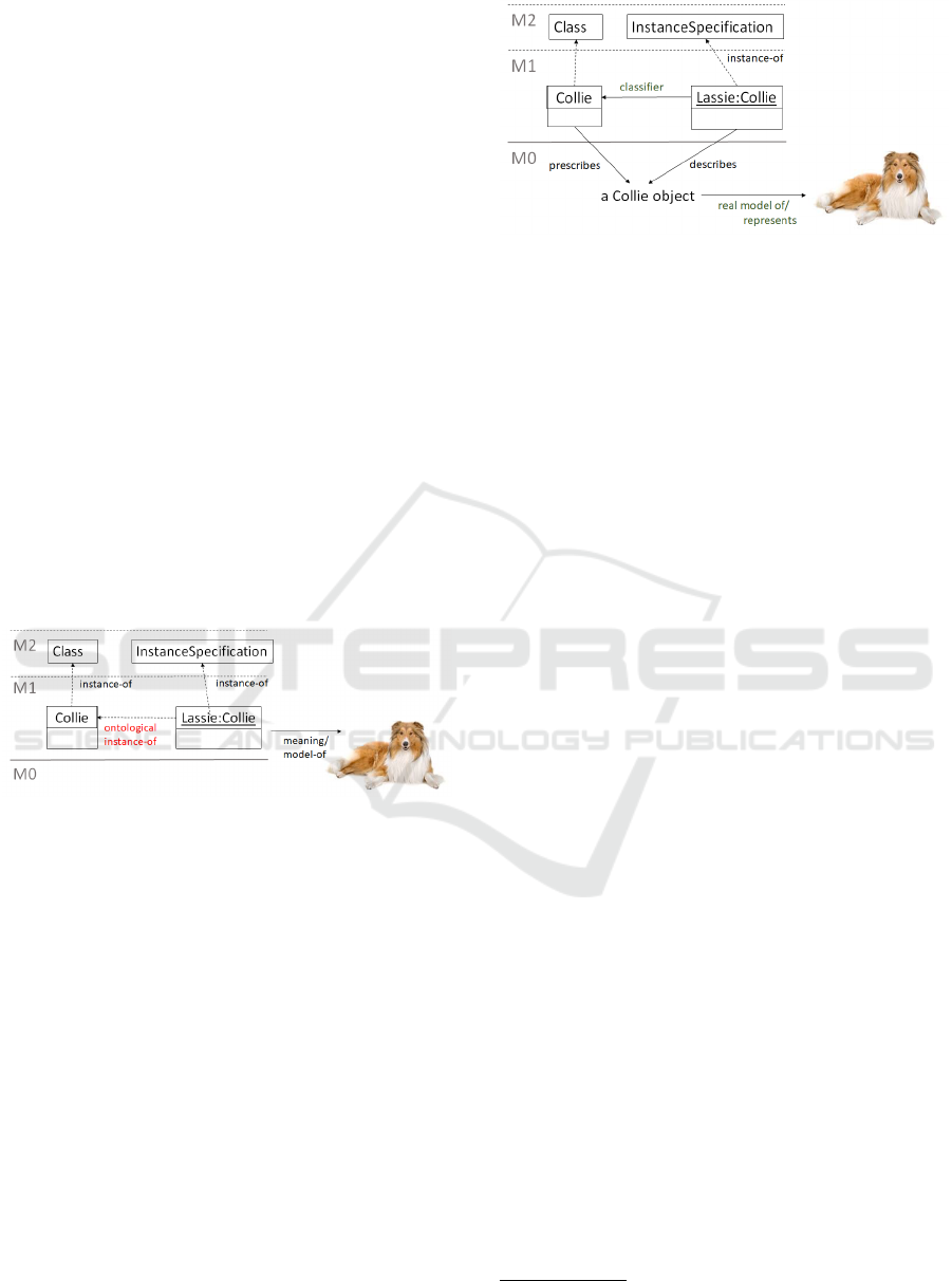
of M0 than ours. As an example, in (Atkinson and
K
¨
uhne, 2003) the Lassie InstanceSpecification
is said to model the real Lassie, see Figure 10.
Figure 10: Ontological instance-of as defined in (Atkinson
and K
¨
uhne, 2003).
The InstanceSpecification Lassie is correctly
placed on level M1 and is an instance of the M2
metaclass InstanceSpecification, which was the
metaclass Object at the time of (Atkinson and
K
¨
uhne, 2003). In addition, Lassie is said to be an
(ontological) instance of the class Collie, thus be-
ing an instance of two classifiers. Objects of the class
Collie as part of model execution at M0 have no role
in ontological metamodeling.
We have seen that for programming (and also for
Executable UML), the objects that model real objects
from the domain (like real passengers, real flights) are
objects at M0 and not at M1, and there is no reason to
distinguish between Executable UML and plain UML
on this issue. With this understanding, the object that
really models the real Lassie is a Collie object at M0.
The Lassie is just a description of the Collie object
that exists as part of the execution at M0, see Figure
11.
Figure 11: The real model of Lassie.
The relation between the Lassie instance specifi-
cation and Collie is that of classifier. Note
that the classifier attribute of Lassie does not
make it an instance of the class Collie. In-
stances of class Collie reside in executions at
M0; Lassie is an instance at M1 of the metaclass
InstanceSpecification at M2.
It is claimed that there is a paradox between
linguistic and ontological instantiation in that on-
tological classes have to be linguistic instance-of a
metaclass on level M3, thereby having a linguistic
instance-of crossing two levels, as ontological classes
are on level M1.
The example used to illustrate this is the notion of
breed. In a linguistic view, Collie is a class at M1,
that is an instance of the metaclass Class on level
M2. Applying an ontological view, the class Collie
is said to be an ontological instance-of a class Breed,
making Breed a kind of metaclass residing at a higher
level than Collie. This way, ontological modeling
becomes metamodeling even though it takes place at
the M1 level.
We will use a programming viewpoint to resolve
(in fact, dissolve) the paradox because things become
more evident when applied to a real case. It is strik-
ing that the whole breed discussion does not relate to
a real application. In a real application, the number of
objects will change during the execution. There will
be so many objects
5
, that it would not be meaning-
ful to make an InstanceSpecification for each of
them in order to describe the execution.
Programs reside on M1, even though program-
mers do not think in these terms. Part of program-
ming is modeling in the sense that domain concepts
are identified and represented by classes, and special-
ized concepts by means of subclasses. This kind of
modeling from programming is not different from the
kind of modeling that is applied when using modeling
languages.
For a programmer, Breed will be a class describ-
5
Considering all possible executions, there are infinitely
many objects to consider.
MODELSWARD 2020 - 8th International Conference on Model-Driven Engineering and Software Development
314

ing the characteristics of breeds, and there may be
subclasses for the various breeds. Dog will be an
abstract subclass of class Canine, and it will have a
Breed property as follows.
abstract class Dog extends Canine {
breed: Breed
...
}
Even though there are no pure Dog objects, all
dogs have a breed, therefore the property breed
of the class Dog. Breed is the type of the prop-
erty breed, and the various values are defined, e.g.
as elements of an enumeration or as subclasses of
Breed. A Collie is thereby a subclass of Dog where
breed=CollieBreed for all objects of class Collie
(i.e. it cannot be changed for individual Collie
objects), and each collie is an instance of the class
Collie. There may be other properties of Dog, and
these may be set for the different instances of Collie.
In languages with class attributes, i.e. attributes that
apply to all instances of a class, breed would be
such an attribute. The value breed=CollieBreed as-
signed to breed will be assigned upon creation of a
objects and from then on being constant/final. Note
that we assume the language to only support single
inheritance, so Dog cannot be said to be classified as
both a Canine and a Breed. With multiple inheri-
tance, it would be possible to classify in both direc-
tions.
class Dog extends Canine, Breed {
...
}
Still, this would not help, as the superclass Breed
would have to be a kind of ’virtual superclass’ in or-
der to specify that for Collie the superclass Breed
really should be CollieBreed (a subclass of Breed)
and not Breed. Very few languages support virtual su-
perclasses, so programmers that are modeling will ap-
ply inheritance for the primary classification and then
use properties for secondary characterization.
One may argue that it is not obvious what should
be the primary classification and what should be prop-
erties. However, modeling always uses a particular
viewpoint and a specific purpose, and these will de-
termine the primary classification. In (Eriksson et al.,
2013) a ’language use approach’ is applied to solve
the above mentioned paradox. They also conclude
that there is no paradox, and they use the terms ’sub-
stantial types’ for the primary classification and ’mo-
ment types’ for the types of properties. Ontologies
also make a distinction between classes of objects and
properties of these objects, so there would be no prob-
lem in defining an ontology where breed is a property.
Another argument against Breed being a class and
class Collie being an instance of this is that dogs as
we know them not only have different breeds, they
also have different roles:
class Dog extends Canine {
breed: Breed
role: Role
}
There are, e.g. pet dogs, guide dogs, watchdogs,
shepherd dogs, sledge dogs. Different breeds are
suited for different roles. For example, the collie
breed is suitable for shepherding.
To be complete, the breed attribute is really typed
by a Breed with more than one species involved, e.g.
class BengalCat extends Cat {
breed: Breed (LeopardCat, DomesticCat)
}
where Breed is defined as
class Breed (list<Species>) {}
It would complicate the notion of ontological meta-
modeling further to cover this situation.
5 RELATED WORK
In this section, we review different ways to look at
the term ’model’ and in particular different views on
M0. We have so far only covered the situations where
’model’ is the term used for ’description’ of what will
be at M0, and thereby implicitly a model of some ref-
erent system in some domain. The notion of UML
models as blueprints
6
is very different from this, but
in fact supported by section 6.3.1 in the UML 2.5.1
specification
7
:
For example, for a model of factory processes,
the execution scope may encompass the exe-
cution of those processes within a single fac-
tory, while, for a model of a software program,
the execution scope will correspond to a sin-
gle execution of that program.
For M0, we consider here the following two main ap-
proaches: real-world objects and execution instances,
see also (Gjøsæter et al., 2016). For the approaches
covered in this section, we judge if they resonate with
system development in general and with programmers
in particular, because if not, there will be no chance
that a given approach will be accepted outside the
modeling community.
6
https://martinfowler.com/bliki/UmlAsBlueprint.html
7
https://www.omg.org/spec/UML/2.5.1/PDF
Real Models are Really on M0 - Or How to Make Programmers Use Modeling
315
M0 as Real-world Objects
In this view, M0 is the area of reality containing “real
things” (e.g., real books, passengers and dogs). The
other levels belong to the modeling realm being fun-
damentally different from M0, such that M0 is not
part of the metamodel stack (Eriksson et al., 2013).
James Skene states in (Skene, 2007):
On level M0 are real-world objects. These are
described by UML models at level M1. The
metamodel of UML is at M2, an instance of
the MOF model on level M3.
This view will not resonate at all with Executable
UML, where M0 obviously will have instances of
classes at M1, not “real things”. It also resonates
badly with programmers, as they have instances of
M1 classes at M0. In this approach, we also find
the idea that M1 contains two ontological levels: One
for user classes and one for user class objects. See
also the discussion in Section 4 about ontological in-
stances. Colin Atkinson and Thomas K
¨
uhne state in
(Atkinson and K
¨
uhne, 2003):
The M0 level is no longer inhabited by user
objects, but rather by the real-world elements
that they model. Note that the real Lassie is
said to be represented by object Lassie, i.e.,
“instance-of” is no longer used to character-
ize the real Lassie as an instance of Collie.
User objects (i.e., model representatives of
real-world objects) now occupy the M1 level,
along with the types of which they are (onto-
logical) instances. From level M1 on, every
level is regarded as a model expressed in the
language defined at the level above.
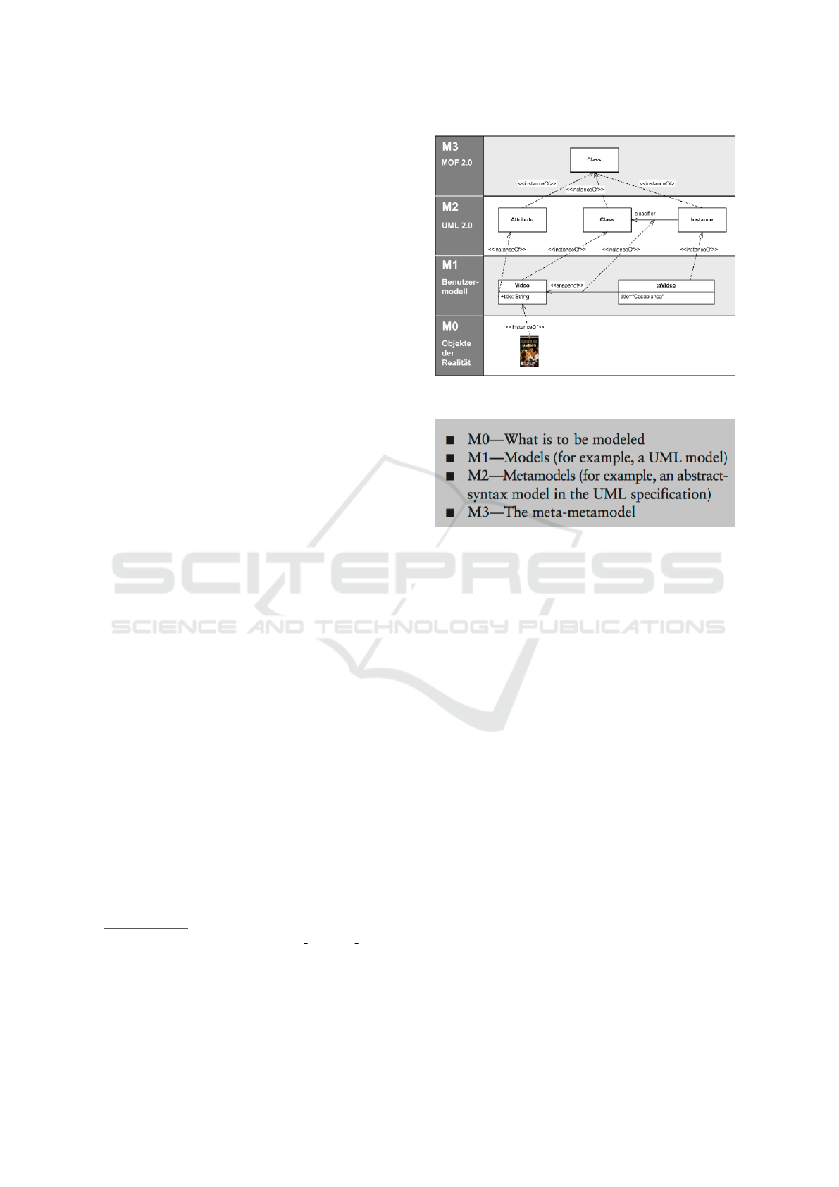
Wikipedia shows the same understanding. The illus-
tration of M0 in Figure 12 is part of the Wikipedia on
UML
8
.
This understanding is said to be based on UML2.3
9
, but is apparently a misunderstanding, as UML2.3
has runtime instances at M0.
In (Seidewitz, 2003) it is referred to what is said
about M0 in MOF1.4
10
: M0 is ’What is to be mod-
eled’, see figure 13:
This is in contrast to the view put forward in this
paper: The real things (phenomena) being modeled
are at the level of M0, but outside the stack, and the
8
https://en.wikipedia.org/wiki/Unified Modeling Language
9
https://www.omg.org/spec/UML/2.3/Infrastructure/PDF
10
Meta Object Facility (MOF) Specification, ver. 1.4,
OMG document formal/02-04-03, Object Management
Group, Apr. 2002, Section 2.2; www.omg.org/technol-
ogy/documents/formal/mof.htm
Figure 12: M0 at Wikipedia.
Figure 13: M0 for MOF 1.4.
objects at M0 model these things. Of course, the ob-
jects in executions at M0 are real-world objects in the
sense that they physically exist in a computer.
M0 with Execution Instances
The objects (in general instances) on M0 are instances
of the class descriptions (in general classifiers) at M1.
Some use the term data instead of instance; as in a hi-
erarchy where a database schema language is on M2,
database schema on M1, and database tables with data
on M0. The model (M1) provides a design of the
system, and level M0 contains the data objects de-
scribed at M1. Runtime instances are an extension of
this view. Instantiation depends upon the semantics
of the language. Colin Atkinson and Thomas K
¨
uhne
state (Atkinson, 1997):
Thus, the information at the data level is
known as an M0 model, the traditional model
level is known as the M1 level, the metamodel
level is known as the M2 level, and so on...
The M0 level is unique because it can contain
no instantiable elements (i.e. templates). It is
unique among the levels, therefore, in being
populated solely by objects.
The execution instances view is supported by (OMG,
2011; Clark et al., 2004; B
´
ezivin and Gerb
´
e, 2001;
MODELSWARD 2020 - 8th International Conference on Model-Driven Engineering and Software Development
316

Favre, 2004). Jean-Marie Favre states in (Favre,
2003):
The model level is used to manage the set
of all possible real-world situations which are
represented at the instance level (M0). For in-
stance “Tom” might be a client that owns two
accounts “a4099” and “a2394” with a respec-
tive balance of $800 and $2000. A point at
the instance level describes a particular state
of a software at a particular point in time. It
corresponds to a program state. Program exe-
cution indeed corresponds to the evolution of
this state.
Jean Bezivin states in (B
´
ezivin and Gerb
´
e, 2001) that
M0 corresponds to one given dynamic execution of a
program. However, it is unrelated to modeling (it does
not contain model elements, but rather real or imag-
inary situational items and facts). A given execution
of a program on level M0 is not itself a model; it is
depicted by a model (the source code of the program
that describes the infinite number of different execu-
tions of the program). Precisely the same situation ex-
ists in the four OMG metamodeling layers: M0: the
concrete level (any real situation, unique in space and
time, represented by a given model from M1).
In (Seidewitz, 2003), the following is said about
models.
A model’s meaning has two aspects. The first
is the model’s relationship to the thing being
modeled. This is meaning in the sense of ’This
class model means that the Java program must
contain these classes.’
This corresponds to the UML-as-blueprint approach
mentioned above. The second aspect (according to
(Seidewitz, 2003)) is in line with the execution in-
stances approach:
The second aspect is the model’s relationship
to other models derivable from it. This is
meaning in the sense of ’This class model
means that instances of these classes are re-
lated in this way.’ I have called this a theory
of the modeling language; this is often called
the modeling language’s ’semantics’ ...
In a presentation
11
at a workshop on unified model-
ing and programming
12
Ed Seidewitz says that ’All
11
https://www.slideshare.net/seidewitz/xuml-
presentation-111023-models-programs-and-x-uml, 2011
12
https://pure.au.dk/portal/en/publications/coomp-2011-
first-international-workshop-on-combined-objectoriented-
modeling-and-programming(77ac2dea-fa3a-49cb-b5b9-
76d6361b447f).html
programs are models’ ’Executable Models are Pro-
grams’, and ’Programming in UML is just Program-
ming’. This view is the same as presented here; the
only difference is that we term the execution a model.
In (Seidewitz, 2016) it is said that Executable UML
models and programs are models of executions.
The notion of executable models was coined way
before plain UML (1997) and therefore before Ex-
ecutable UML. In 1992, SDL (Union, 2011) was
turned into an object-oriented specification language
with well-defined execution semantics, exploiting
processes with state machines, and in 1994 ROOM
(Selic et al., 1994) did the same with processes and
Statecharts.
6 SUMMARY
This paper has clarified artefacts like models, descrip-
tions and executions, and the relations between these
artefacts in systems development.
Executing a System Description Leads to a System.
In this paper we have argued that in order to have
programmers employ modeling for real, a model
has to be the executing system of objects that has
a model-of relation to a planned system. Such a
model will have a system model prescription, and
the execution of this prescription will create the
model. In UML, this system model description is
called a UML model.
A System Can be Model-of a Referent System. It
appears quite obvious in a programming context
that some objects (existing during the execution
of a program) model the corresponding entities
in the application domain. This view applies to
modeling as well.
Ontological Instantiation Relates Descriptions.
The possibility to describe objects in UML
using InstanceSpecification has created
considerable confusion about the levels, about
instantiation, and about M0. The idea of models
being executions at M0 helps in understanding
that there is a major difference between onto-
logical instantiation and linguistic instantiation.
Based on this difference, ontological instantiation
is only a relation between different description
elements: InstanceSpecification and its
classifier.
Model and Code can Describe the Same System.
A UML model does not model the corresponding
Java code, but both are descriptions of systems
that might model some referent system. They can
Real Models are Really on M0 - Or How to Make Programmers Use Modeling
317

describe the same system on different levels of
abstraction.
These clarifications contribute to the alignment of
programming and modeling. This paper has just
touched upon semantics and meaning; an in-depth
coverage of semantics and meaning, which are closely
related to M0, is planned for a future article.
REFERENCES
Aldrich, J., Chambers, C., and Notkin, D. (2002). Archjava:
Connecting software architecture to implementation.
In Proceedings of the 24th International Conference
on Software Engineering, ICSE ’02, pages 187–197,
New York, NY, USA. ACM.
Aßmann, U., Zschaler, S., and Wagner, G. (2006). Ontolo-
gies, meta-models, and the model-driven paradigm.
In Calero C., Ruiz F., Piattini M. (eds): Ontologies
for Software Engineering and Software Technology.
Springer Berlin Heidelberg.
Atkinson, C. (1997). Meta-modeling for distributed ob-
ject environments. In In Enterprise Distributed Object
Computing, pages 90–101. Published by IEEE Com-
puter Society.
Atkinson, C. and K
¨
uhne, T. (2003). Model-driven develop-
ment: A metamodeling foundation. Software, IEEE.
B
´
ezivin, J. and Gerb
´
e, O. (2001). Towards a Precise Defi-
nition of the OMG/MDA Framework. Proceedings of
ASE’01, Automated Software Engineering.
Bossel, H. (2013). Modeling and Simulation.
Vieweg+Teubner Verlag.
Butting, A., Jansen, N., Rumpe, B., and Wortmann, A.
(2018). Translating grammars to accurate metamod-
els. In Proceedings of the International Conference
on Software Language Engineering (SLE’18).
Clark, T., Evans, A., Sammut, P., and Williams, J.
(2004). Applied Metamodelling. A Foundation for
Language Driven Development. Xactium. Available
at http://www.xactium.com.
Daun, M., Brings, J., Krajinski, L., and Weyer, T. (2019).
On the benefits of using dedicated models in valida-
tion processes for behavioral specifications. In Pro-
ceedings of IEEE/ACM Internatioal Conference and
System Processes (ICSSP).
Eriksson, O., Henderson-Sellers, B., and
˚
Agerfalk, P. J.
(2013). Ontological and linguistic metamodelling re-
visited: A language use approach. Information and
Software Technology.
Exner, K., Lindowa, K., Buchholz, C., and Stark, R. (2014).
Validation of product-service systems – a prototyping
approach. In Proceedings of 6th CIRP Conference on
Industrial Product-Service Systems.
Favre, J.-M. (2003). Meta-model and model co-evolution
within the 3D software space. In Proceedings of
ELISA 2003.
Favre, J.-M. (2004). Foundations of meta-pyramids: Lan-
guages vs. metamodels - episode ii: Story of thotus the
baboon. In Language Engineering for Model-Driven
Software Development.
Fischer, J., Møller-Pedersen, B., and Prinz, A. (2016). Mod-
elling of systems for real. In Proceedings of the 4th In-
ternational Conference on Model-Driven Engineering
and Software Development, pages 427–434.
Fowler, M. (2005). Language workbenches: The
killer-app for domain specific languages?
http://www.martinfowler.com/articles/language
Workbench.html.
Gjøsæter, T., Prinz, A., and Nytun, J. P. (2016). MOF-VM:
Instantiation revisited. In Proceedings of the 4th In-
ternational Conference on Model-Driven Engineering
and Software Development, pages 137–144.
Holbæk-Hanssen, E., H
˚
andlykken, P., and Nygaard, K.
(1973). System description and the delta language.
Technical report, Oslo: Norwegian Computing Cen-
ter.
Kawata, S. (2015). Computer Assisted Problem Solving En-
vironment (PSE), pages 1251–1260. IGI Global.
K
¨
uhne, T. (2006). Matters of (meta-) modeling. Software
and Systems Modeling (SoSyM), 5(4):369–385.
Madsen, O. L. and Møller-Pedersen, B. (2018). This is not
a model : On development of a common terminology
for modeling and programming. In Proceedings of the
8th International Symposium, ISoLA 2018: Leverag-
ing Applications of Formal Methods, Verification and
Validation - Modeling, Lecture Notes in Computer Sci-
ence 2018 ;Volume 11244 LNCS, pages 206–224.
OMG (2011). Unified Modeling Language: Infrastructure
version 2.4.1 (OMG Document formal/2011-08-05).
OMG Document. Published by Object Management
Group, http://www.omg.org.
OMG (2014). Ontology Definition Metamodel Version 1.1.
Technical report, Object Management Group.
OMG (2016). Meta Object Facility (MOF). Technical re-
port, Object Management Group.
OMG (2018). Semantics of a Foundational Subset for Exe-
cutable UML Models (fUML). Technical report, Ob-
ject Management Group.
Prinz, A., Møller-Pedersen, B., and Fischer, J. (2016).
Object-oriented operational semantics. In Proceed-
ings of SAM 2016, LNCS 9959, Berlin, Heidelberg.
Springer-Verlag.
Seidewitz, E. (2003). What models mean. IEEE Software.
Seidewitz, E. (2016). On a unified view of modeling
and programming, position paper. In Proceedings of
ISoLA 2016.
Selic, B., Gullekson, G., and Ward, P. T. (1994). Real-time
Object-oriented Modeling. John Wiley & Sons, Inc.,
New York, NY, USA.
Skene, J. (2007). Language Support for Service-Level
Agreements for Application-Service Provision. PhD
thesis, University of London. Accessed January, 2015:
http://eprints.ucl.ac.uk/5607/1/5607.pdf.
Union, I. T. (2011). Z.100 series, specification and de-
scription language sdl. Technical report, International
Telecommunication Union.
W3C (2012). OWL 2 Web Ontology Language. Technical
report, W3C.
MODELSWARD 2020 - 8th International Conference on Model-Driven Engineering and Software Development
318
