
Design and Development of IoT based Computer Network Room
Environment Monitoring System
Fahd A. Banakhr
Department of Electrical and Electronic Eng., Yanbu Industrial College, Royal Commission of Yanbu, Saudi Arabia
Keyword: IoT, Internet of Things, NRMS, Network Room, Power, Temperature, Humidity.
Abstract: This paper discusses design and development of internet of thing (IoT) based computer network room
monitoring system (NRMS) for twenty five rooms of college campus. Furthermore, it also discusses the
benefits of Internet of things offer as compare to traditional method of monitoring which does not cope with
rising demand of dynamic power used by servers and networking devices. The NRMS deals with
monitoring network room environmental conditions like power, temperature, and relative humidity. The
system then sends this information to the IoT cloud and displays the live data on the dashboard. It also sends
alert to the authorized persons; records the previous data to find any root cause of the problem if needed.
The data updated periodically from the implemented system can be accessible through internet from
anywhere in the world.
1 INTRODUCTION
The Internet of Things (IoT) is a new growing area
that is gaining ground at very fast pace with virtue of
sophisticated communications technologies. The
basic idea of this concept is the ubiquitous presence
around us of a variety of things or objects various
sensors, actuators, cell phones by using different
protocols and schemes, are able to cooperate with
each other and work together with their neighbors to
reach common goals (Ashrae, 2011). IoT based
NRMS take the benefits of IoT to solve problem and
protect the network to go down. Every network room
is monitored by one NRMS box for multi parameters,
if something goes wrong it take suitable action to
resolve the problem. Thing Speak API is used IoT
base for data recording and root cause analyses of the
problem and serves as an interface between devices
such as temperature, humidity and power sensors to
collect data and analysis software to analyze data to
generate alerts and alarms as required.
2 PROBLEM DEFINATION
The network is room environment is most critical
factor for the efficient working and operating life of
servers and networking switches and other devices,
not proper monitoring can not only damage the
equipment but also halt major work in the
organization.
The impact of downtime ranges from
direct loss of revenue to the decreased performance
of the organization and spoil reputation. Problem
faced by IT networking devices are listed below.
2.1 High Network Room Temperature
High network room temperature can damage the
hardware of IT equipment present in the room, even
short time rise in the temperature can have worse
consequence. It can create intermittent failure of
equipment as well as permanent data loss. High
temperature can be potential risk for the installation
to catch fire (Stanford University, 2011).
2.2 Low Network Room Temperature
Keeping temperature below the specified limited by
the manufacturer is energy waster, because it require
cooling system to run continuously to maintain the
temperature it can also create health related issues for
the IT personal working in the room. Furthermore it
is heavy on the company budget (ASHRAE, 2008).
2.3 Low Network Room Humidity
Dry climate increases the probability of electrostatic
discharge. Which can cause intermittent or
Banakhr, F.
Design and Development of IoT based Computer Network Room Environment Monitoring System.
DOI: 10.5220/0008925201530160
In Proceedings of the 5th International Conference on Internet of Things, Big Data and Security (IoTBDS 2020), pages 153-160
ISBN: 978-989-758-426-8
Copyright
c
2020 by SCITEPRESS – Science and Technology Publications, Lda. All rights reserved
153
permanent failure of electronic components.
Repairing damaged components can be expensive
and time consuming (Swenson, D., & J.T. Kinnear,
2009).
2.4 High Network Room Humidity
High humidity level in network rooms can cause
internal components of IT equipment to rust and
change their electrical properties, such as resistance
and capacitance or thermal conductivity. Short-
circuit can be one critical outcome of high humidity,
fire, data storage devices failure and financial loss to
company is consequence (TIA, 2005).
2.5 High Network Room Sound Level
High Sound level in network room is used to monitor
the working of fans of IT equipment, very high sound
level indicate that fan of IT equipment
malfunctioning and to be fixed early as possible to
prevent catastrophic failure. Very High sound in the
server rooms can also cause hearing impairment to IT
personal working or sitting in the room (Dubravko,
2016).
2.6 Low Network Room Sound Level
Low sound level indicate that fan of equipment not
working or running at low speed. Observing sound
levels allows IT personnel to identify a problem as
early as possible.
2.7 Network Room Power Failure
In normal circumstances, Network room power is
backed up by uninterruptable power supply UPS
system some time UPS and main Power failure occur
at same time which halt the communication process
in organization (UPS, 2018).
2.8 Remote Connectivity and Alert
Network room are usually located at isolated place in
the organization, remote monitoring is essential for
these type of system to send alert to IT personal to
take require action.
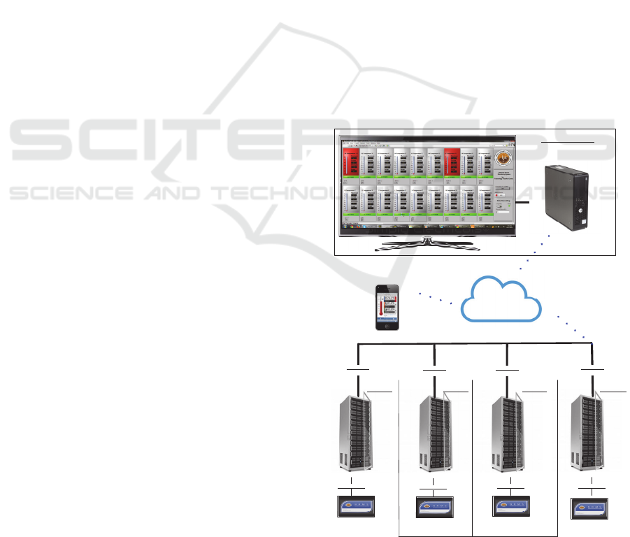
3 SYSTEM ARCHITECTURE
System level diagram is shown below that shows IoT
cloud service ThingSpeak is used by our system to
display data globally on internet. ThingSpeak is base
platform for the Internet of Things applications.
ThingSpeak allows to build an application around
data collected by sensors on different location. Major
advantage of ThingSpeak include: real-time data
collection, data processing, visualizations, apps, and
plugins. Control room display real time data
collected by different sensors from various location.
Fig.1 shows network rooms are connected with
monitoring systems which is placed in rack or
suitable place connected to internet to take fast and
effective decisions. Data can be displayed on
handheld devices based on android and iPhone. All
the data gathered from network rooms is displayed
control room screen, which gives alerts to the IT
technician if something goes wrong.
Individual sensors do not typically connect
individually to the IP network. Instead, the NRMS
box interpret the sensor data and send data to the
central system by IoT cloud This distributed monitor-
ing architecture dramatically decreases the number of
network drops required and reduces the overall
system cost and management burden. NRMS box are
typically assigned to physical network room within
the organization and combine sensors from a limited
area in order to limit sensor wiring complexity.
ETHERNET ETHERNET
ETHERNETETHERNET
ROOM 1 ROOM 2 ROOM 3 ROOM N
CONTROL ROOM
Monitor Any Where
WIFI/EthernetWIFI/EthernetWIFI/Ethernet
WIFI/EthernetWIFI/Ethernet
WIFI/Ethernet WIFI/Ethernet
IoT Cloud
Figure 1: Network rooms are connected with monitoring
system.
IoTBDS 2020 - 5th International Conference on Internet of Things, Big Data and Security
154
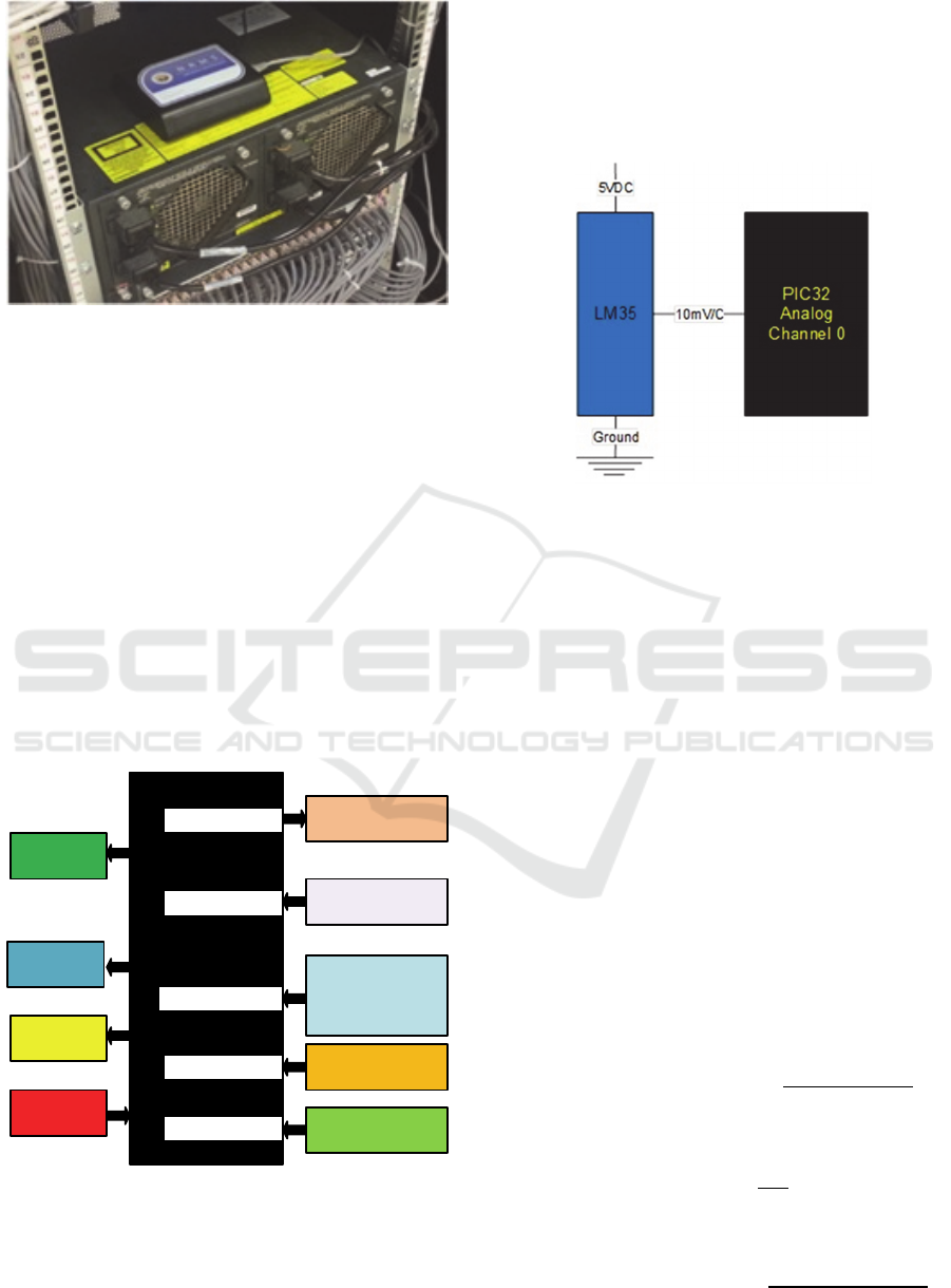
Figure 2: NRMS box connected to one of the servers.
The heart of the IoT NRMS is microchip
PIC32MX360 microcontroller which gives a rich
peripheral set at a low cost for a broad range of
embedded designs that require complex code and
higher feature integration. Block diagram of the
system is shown in figure 3.
The major advantage of PIC32 microcontroller is
one failure every 16.58 years that make it ideal for
monitoring expensive IT equipment. Furthermore, it
can operate at over 100 MHz and can operate in
temperature range from -40 to 105 centigrade. It has
built-in16 channels 10bit ADC that can operate on 1
mega sample per second. Microcontroller has on
chip fail-Safe Clock Monitor that allows safe
shutdown in case of clock failure (Microchip
datasheet, 2011).
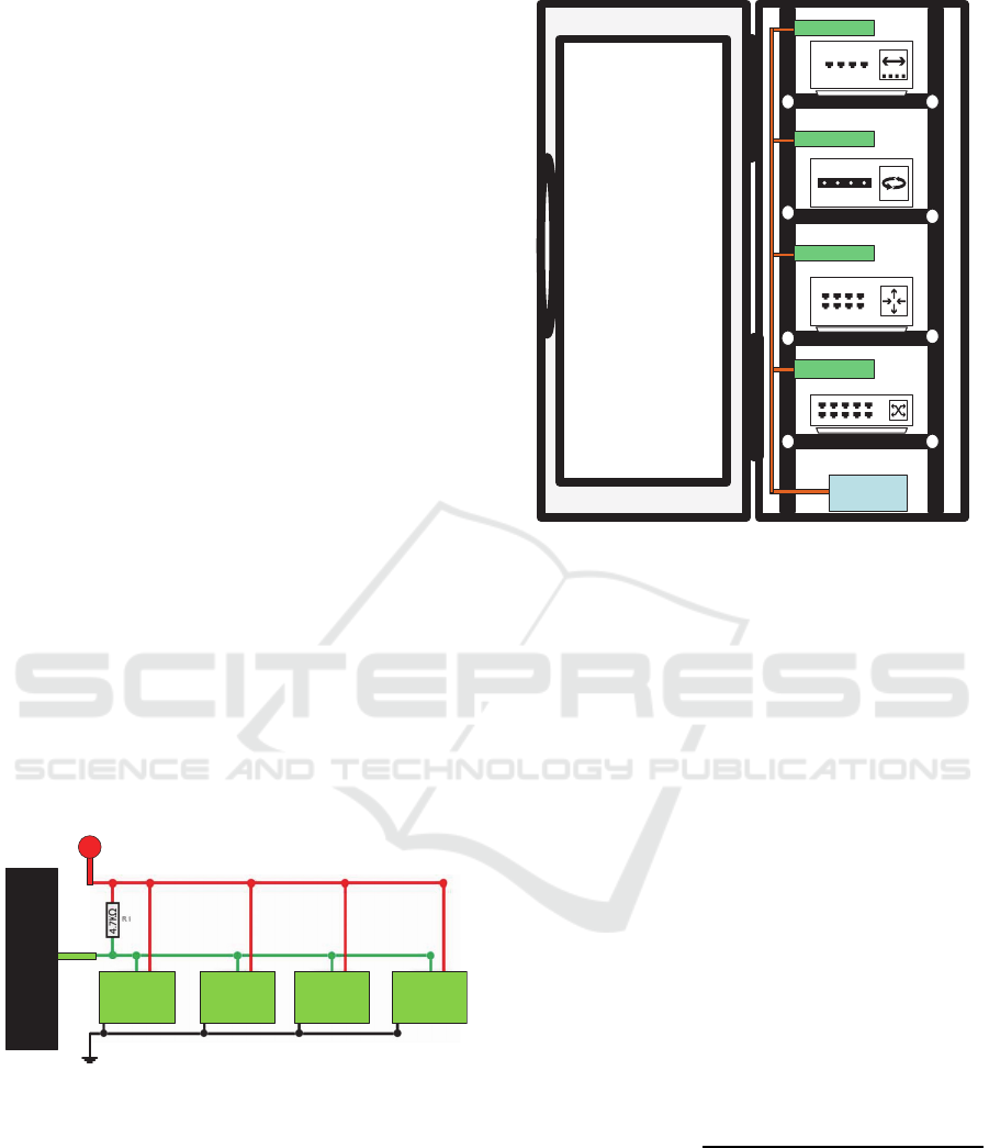
PIC32MX360
Error LED
Temperature
Senso r LM35
Multiple
Temperature
Senso rs
DS18B20
An alog
Digital o ut put
On e Wire In pu t
Humidity S en sor
So un d S en sor
I2C
An alog In pu t
Et her n et
WIFI
USB
Power
Monitor
Figure 3: Block diagram of connected system.
3.1 Air Temperature Monitor
LM35 is used to check the air temperature of the
network room The LM35 is low temperature sensor
with an output voltage linearly proportional to the
Centigrade temperature. The LM35 device does need
any external calibration or trimming to provide
typical accuracies of ±0.25°C at room temperature
and 0.75°cover a full −55°C to 150°C temperature
range (Texas instrument datasheet, 2017).
Figure 4: LM35 sensor connected to PIC32 to check the
temperature of the network room.
By using this simple circuit to monitor air
temperature of the network give benefits as written,
Monitor the room for high temperature due
to cooling system malfunction or total
failure to protect and extent life of
equipment.
Monitor for very low temperature save
Energy by keeping the temperature at
desired level as consequence save energy
and money.
Monitor sudden rise of temperature in the
room to protect critical data storage system
from damage. Following equations are used
to calculate the temperature in the software
application.
𝑇𝑒𝑚𝑝𝑒𝑟𝑎𝑡𝑢𝑟𝑒 𝑖𝑛 𝐶𝑒𝑛𝑡𝑖𝑔𝑟𝑎𝑑𝑒
LM35 Voltage
10 mV/C
LM35 Voltage ADC reading ∗
ADC resolution mV/ bit
ADC resolution
mV
bit
3.3mV/bit
𝑇𝑒𝑚𝑝𝑒𝑟𝑎𝑡𝑢𝑟𝑒 𝑖𝑛 𝐶𝑒𝑛𝑡𝑖𝑔𝑟𝑎𝑑𝑒
3.3 ∗ ADC reading
10
Design and Development of IoT based Computer Network Room Environment Monitoring System
155
3.2 Network Room Rack Temperature
Monitor
Network Room rack is monitored by using DS18B20
single wire temperature sensors. these sensors can be
network together on singe input pin of
microcontroller with cable length up to 3 meters. The
measurement ranges of these sensor are -50 to
+125⁰C. Each DS18B20 has a unique 64-bit serial
address, which allows multiple DS18B20s to
function on the same1-Wire bus. One digital input is
of pic32 microcontroller is used to control many
DS18B20s distributed over IT equipment rack
(Maxim integrated datasheet, 2015). While
measuring room air temperature in the essential, the
real. concern is the temperature inside the racks.
There are many variables that affect how rack
temperature varies from network room temperature
The only way to monitor for sure that equipment is
operating in a safe temperature is to note the
temperature inside the rack itself. This will save time
in troubleshooting as well as save other equipment
from overheating and extent the overall life.
DS18B20 Temperature = (Temperature High Byte 8
+ Temperature Low Byte) *0.0625
Figure 5 shows single wire connection of four
temperatures sensor placed at different location in the
network room. Figure 6 shows the placement on
temperature sensor at different response (Maxim
integrated, 2015).
DS18B20
2
DS18B20
1
DS18B20
3
DS18B20
4
DIO
PIC32
Digital
input
3.3
V
Figure 5: Single wire connection.
3.3 Network Room Rack Humidity
Monitor
The humidity of the air is a measure of the amount of
water vapors content it holds. Relative humidity
(RH) is a convenient way of expressing the amount
of water vapor contained in a volume of air. It's
defined as the ratio expressed in percentage of the
mass of water vapor in the air to the mass required to
DS18B20
DS18B20
DS18B20
DS18B20
NRMS
Box
Figure 6: Placement of temperature sensors.
produce saturation at the same temperature. When
the air is saturated, therefore, its RH is 100%. For
this system low cost Honeywell HIH8120-021-001
humidity sensor is selected, main reason of this
selection is, it can operate on high temperature range
of -40 to 125 centigrade with accuracy of ±2.0 %RH
(Honeywell datasheet, 2015). Moreover, it also
eliminates the need to regularly recalibrate the
sensor, which can be troublesome and pricey. It has
very low power consumption the sensor goes into
sleep mode when not taking Measurement,
consuming only 1 μA versus 650 μA figure 7 shows
hardware interface to humidity sensor with
microcontroller by simple I2C protocol. This solution
protects equipment failure from static electricity
accumulation at low humidity points and
condensation formation at high humidity points on
the IT equipment. Following formula is used to
calculate the humidity (%RH).
Humidity %RH
Humidity Output Count ∗ 100
16383
IoTBDS 2020 - 5th International Conference on Internet of Things, Big Data and Security
156
HIH8120-021-001
VDD SCL
SDAVSS
3.3
V
PIC32
Figure 7: Hardware interface to humidity sensor with
microcontroller.
3.4 Network Room Sound Monitor
Sound monitor circuit uses SEN-14262 sound
detector based on microphone and audio amplifier
(Spark Fun online, 2018). The Sound monitor has
three separate outputs. One is amplified audio output
from microphone, second is sound envelope and third
is pulse output when sound above threshold is
detected. Microcontroller analog pin is connected
with envelope pin of sound detector to identify audio
level which indicate malfunctioning of fans
Sound Detector
Read Analog Value from ADC
If sound level is greater than 30 means very
noisy,
may be fans are dusty.
If sound level is less than 10 fan is not
working
check the fan
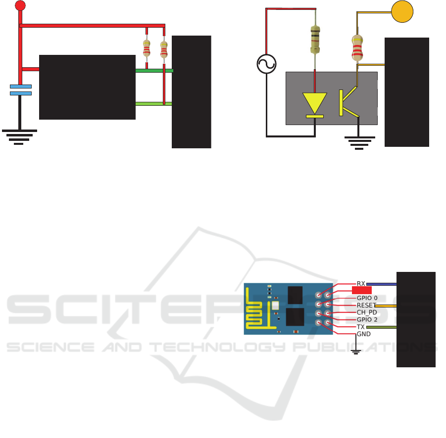
3.5 Network Room Power Monitor
Simple opt coupler is used to detect the power failure
from the main socket this simple circuit work on
UPS power to detect the condition of main power. If
is power for long time it will send alert to concerned
maintenance technicians.
Ethernet cable of NRMS is connected with main
switch or hub in when power is loss by the switch
communication loss error due to power is send to the
control room.
PIC32
AC
3.3VDC
Figure 8: Power failure detection.
3.6 NRMS Wifi Communication
In this project ESP8266 IoT wifi module is used
which is very low cost with a complete AT command
library. This allows for stress-free integration with a
Wi-Fi network through serial communication.
Module has low power consumption at sleep mode
(Spark Fun online, 2018).
PIC32
VCC
Figure 9: ESP8266 IoT WiFi module.
4 SYSTEM SOFTWARE
DESCRIPTION
System software has four major components
Application programming interface API and Web
Service for the Internet of Things, embedded
software for microcontroller, LabVIEW program for
main control panel software, and mobile software for
remote monitoring. Following paragraphs discuss the
implementation.
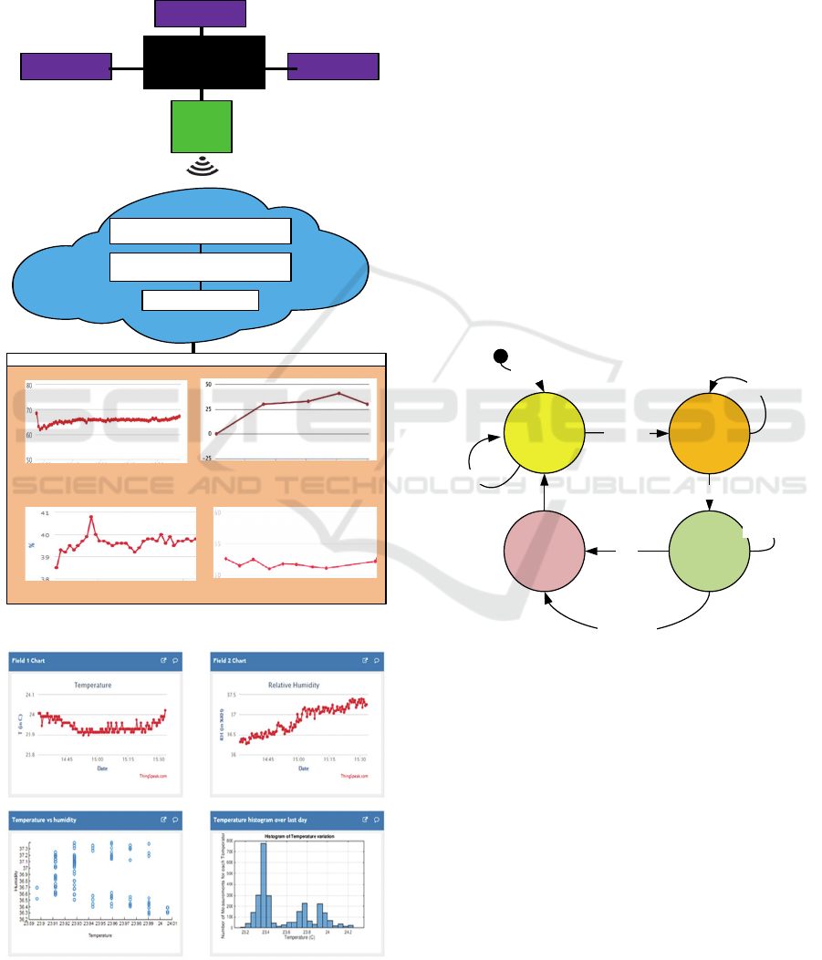
4.1 API and Web Service for the IoT
For the purpose of connecting an NRMS to the IoT,
system uses ThingSpeak API (ThingSpeak, 2018).
Fig 10 represents the connections of system
The API provides simple communication capabilities
to objects within the IoT environment, as well as
Design and Development of IoT based Computer Network Room Environment Monitoring System
157
interesting additional feature like tweeter interface.
Additionally, ThingSpeak permits to build software
applications around data collected by sensors by
NRMS Data is stored in. the channel that is primary
component of ThingSpeak, which holds data fields,
location fields, and a status field. Real-time snapshot
of thingspeak is shown in the figure 11.
Create a Channel and
collect data
Analyze and Visualize
the data
Act on the data
PIC32
Sensor
ThingSpeak
Temperature Room 1
Temperature Room 2
Humidity Room 1
Humidity Room 2
WIFI
Module
Webpage
Sensor
Senor
Figure 10: Connection system of NRMS to IoT.
Figure 11: Real-time snapshot of thingspeak.
4.2 PIC32 Microcontroller Ethernet
Program
The microcontroller uses microchip TCP/IP stack
that provide a foundation for embedded IoT network
applications by handling most of the interaction
required between the physical network port and
sensing application. They stack provide for
complicated network layers free of cost on embedded
microcontroller that include HTTP for serving web
pages, SMTP for sending e-mails, SNMP for
providing status and control. Microchip’s TCP/IP
stack uses of cooperative multitasking to implement
the various TCP/IP stack functions and collect sensor
data, which all cooperate, to share processing time on
a single microcontroller. In other words,. This is done
by either dividing its job into multiple tasks, or
organizing its main job into a Finite State Machine
(FSM) and dividing a long job into multiple smaller
jobs. Each job has been planned to cooperate by
running only a short time so that the other tasks can
have their share of the processor. State diagram of
microcontroller program is shown in fig. 12.
Connection
Established
Disconnected
Read sensors
data
Initial
Failed
Success
Yes
Quit
Open Socket
No
Disconnect
Not finish
Figure 12: State diagram of microcontroller program.
4.3 PIC32 Microcontroller Wi-Fi
Program
The ESP8266 Wi-Fi module has a full TCP/IP stack
support. It can effortlessly have configured as a web
server or client by use of serial port of
microcontroller. The module accepts serial AT
commands and responds back with the operation's
outcome. Moreover, once the device is connected
and is set to accept connections, it will send
spontaneous messages whenever a new connection or
a new request is issued. Communication algorithm
IoT cloud and Wi-Fi module is shown in figure 13.
IoTBDS 2020 - 5th International Conference on Internet of Things, Big Data and Security
158
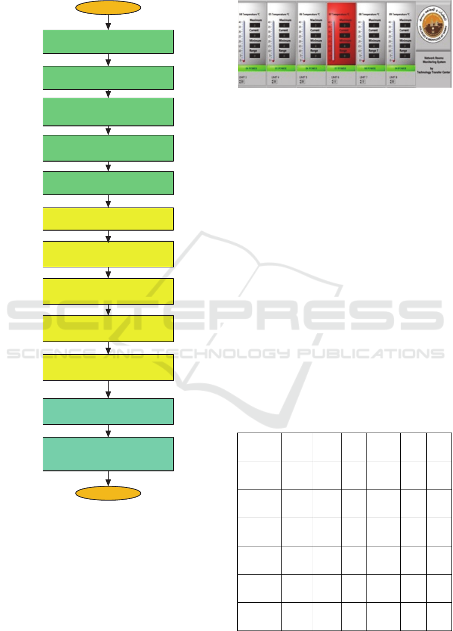
START
Reset Module
AT+RST
Configure Access point
AT+CWMODE
Ge t IP add ress
AT+CIFSR
Multiple Connections
AT+CIPMUX=1
Read temperature from
LM35
Read temperature from
DS18B20
Read Relative Humidity
Read Sound data
Read Power status
Establish TCP Connection
AT+CIPSTART
Send Sensor Data to
IoT Cloud
AT+CIPSEND
Establish Serial
connection with ESP
END
Figure 13: Communication algorithm IoT cloud and Wi-Fi
module.
4.4 Main Control Room Software
Main control software display information from the
all network rooms in one place developed using
LabVIEW (LabVIEW, 2017). Figure 14 shows
sensors and power information displayed on main
screen on the control room.
Figure 14: Sensors and power information displayed on
main screen on the control room.
User can set the desired threshold of sensors for
generating alerts and alarm from main control panel
software for IT Staff. Based on the severity level of
an alert system decide the action to be taken These
automated actions could be personnel email or cell
phone text message notification, or they could be
corrective actions such as triggering back up cooling
fans or dryer
Historical recoding of sensors data is implemented in
the program Data can be used to predict future
behavior as more and more equipment are aggregated
in the room, and could help forecast when the data
room will reach to the limit. Long term historical
data analysis can be used at the rack level to compare
how equipment from different manufacturers in
different racks, which may guide future purchases
recording.
5 RESULTS
Table 1 shows the result of Implementing the NRMS
in different locations in the campus.
Table 1: RCYCI Communication Room Temperature.
Location
MAC
Address
BOX
Mean
Temp
Mean
Relt.
Humidity
Power
Status
Sound
Level
YIC Main
Data
Center
00-04-
A3-F4-
C0-06
NRMS0
9
20 62 OK OK
YIC ACX
Comm
room
00-04-
A3-F4-
BB-04
NRMS0
3
22 60 OK OK
YIC AC
Server
Room
00-04-
A3-F4-
C0-1B
NRMS0
7
21 61 OK OK
YIC New
Dorm B#1
00-04-
A3-F4-
BB-46
NRMS1
4
25 60 OK OK
YIC New
Dorm B#7
00-04-
A3-F4-
B7-F0
NRMS0
1
24 63 OK OK
YTI Main
Server
Room
00-04-
A3-F4-
BC-97
NRMS0
6
20 62 OK OK
Design and Development of IoT based Computer Network Room Environment Monitoring System
159

Table 1: RCYCI Communication Room Temperature
(cont.).
Location
MAC
Address
BOX
Mean
Temp
Mean
Relt.
Humidity
Power
Status
Sound
Level
YTI B2
Comm
Room
00-04-
A3-F4-
BE-F5
NRMS1
8
21 60 OK OK
YTI B4
Comm
Room
00-04-
A3-F4-
BE-99
NRMS1
2
26 59 OK OK
YTI B5
Comm
Room
00-04-
A3-F4-
C8-18
NRMS0
5
28
58 OK OK
YUCM J1
Server
room
00-04-
A3-F4-
B7-20
NRMS1
1
20 60 OK OK
YUCM J2
Server
room
00-04-
A3-F4-
BF-A9
NRMS0
2
23 61 OK OK
YUCM J1
Comm
room
00-04-
A3-F4-
BB-65
NRMS1
5
24 62 OK OK
YUCF
Buildg A
00-04-
A3-F4-
C0-4C
NRMS1
6
27
61 OK OK
YUCF
Buildg B
00-04-
A3-F4-
A5-04
NRMS0
8
20 60 OK OK
YUCF
Buildg C
00-04-
A3-F4-
C2-40
NRMS1
0
22 62 OK OK
YUCF
Buildg D
00-04-
A3-F4-
BB-0D
NRMS1
7
21 63 OK OK
YUCF
Buildg E
00-04-
A3-F4-
C0-45
NRMS1
3
23 64 OK OK
Monitoring system
*YIC, refers to Yanbu Industrial College.
*YUCM, refers to Yanbu University College Male
Campus.
*YUCF, refers to Yanbu University College Female
campus.
*YTI, refers to Yanbu Technology Institute.
6 CONCLUSION
IoT based NMRS provide protection against
environmental threats that is critical to a
comprehensive network equipment safety strategy.
Location and procedure of temperature, humidity,
and sound sensing equipment requires assessment,
choice, and design, best practices and design tools
are available to support for efficient and effective
deployment. IoT software and control program
manage the collected data and provide recording,
analysis, smart alerts and automated corrective and
preventive action as desired. By utilizing IoT for
monitoring dispersed physical threats in different
network room enables the IT administrator to fill
critical cracks in overall network safety to achieve
the required goals.
REFERENCES
ASHRAE, 2011. Thermal guidelines for data processing
environments – expanded data center classes and
usage guidance. TC 9.9, ASHRAE, Atlanta, USA,
2011.
Stanford University Server/Telecom Rooms Design
Guide. Stanford, CA: Stanford University, 2011.
ASHRAE. Environmental Guidelines for Datacom
Equipment— Expanding the Recommended
Environmental Envelope. Developed by ASHRAE TC
9.9. 2008.
Swenson, D., J.T. Kinnear. 2009. The Role of Relative
Humidity and Dew Point on Electrostatic Charge
Generation and Discharge (ESD). The Green Grid.
TIA-942-2005. Telecommunications infrastructure
standard for data centers, Washington, DC: American
National Standards Institute, 2005.
Dubravko,”MiljkovićNoise within a data center”, In Proc.
Information and Communication Technology,
Electronics and Microelectronics (MIPRO), 2016.
UPS failures continue to be the top cause of data center
downtime [online] http://www.geistglobal.com/news/
company-blog/ups-failures-continue-be-top-cause-
data-center-downtime [Accessed jan. 10, 2018]
Microchip “PIC32MX3XX/4XX Family Data Sheet”,
2011.
Texas instrument “LM35 Precision Centigrade
Temperature Sensors”, Datasheet 1999, [Revised
2017].
Maxim integrated “ DS DS18B20 Programmable
Resolution 1-Wire Digital Thermometer”, datasheet,
2007 [Revised 2015].
Maxim integrated ,Guidelines for Reliable Long Line 1-
Wire Networks”, Application notes 148.
Honeywell “HumidIcon™ Digital Humidity/Temperature
Sensors, HIH8000 Series”, Datasheet, 2015.
Spark Fun Sound Detector “https://www.sparkfun.com/
products/14262 “[Accessed jan. 10, 2018].
WiFi Module - ESP8266,”https://www.sparkfun.com/
products/13678”, “[Accessed Jan. 9, 2018].
ThingSpeak,” https://thingspeak.com/”, [Accessed Jan.11,
2018].
LabVIEW , LabVIEW 2017, http://www.ni.com/”.
IoTBDS 2020 - 5th International Conference on Internet of Things, Big Data and Security
160
