
Individual Avatar Skeletal based Animation Feedback
for Assisted Motion Control
Lars Lehmann
1 a
, Christian Wiede
2 b
and Gangolf Hirtz
1 c
1
Digital Signal Processing and Circuit Technology, Chemnitz University, Reichenhainer Str. 70, Chemnitz, Germany
2
Fraunhofer IMS, Finkenstr. 61, Duisburg, Germany
Keywords:
Visualisation, Feedback Control, Assisted Motion Control, Motion Error Detection, 3D Realtime Animation.
Abstract:
In medical training therapy (MTT), the precise execution of the training exercises is of decisive importance
for the success of the therapy. Currently, a therapist has to treat up to 15 patients simultaneously on an
outpatient basis. Recently an assistance system that can assess both the quantity and the quality of movement
was developed. A feedback system models target-oriented recommendations for actions and communicates
them directly to the patient. A hardware accelerated visualisation system using OpenGL and GLSL shaders
was realised to animate a real-time rendered 3D mesh connected to an extracted motion skeleton. An avatar
visualises the error by colouring the body regions with traffic light trenches. The individualisation of the
underlying three-dimensional avatar increases the willingness of the patients to participate in the exercises
which they perform autonomously without the supervision of therapists.
1 INTRODUCTION
After a hip operation, the treated persons have to com-
plete a rehabilitation phase lasting several weeks in a
special MTT centre. In the MTT, up to 15 patients are
monitored simultaneously by a therapist (Nitzsche,
2018). Therefore, there is no guarantee that the ther-
apist will have a constant overview of every single
patient in the rehabilitation centre. This lack of con-
trol can have a negative effect, since in the unob-
served moments movement errors are performed by
the patient, which, above a certain number, have an
extremely negative effect on the treatment (L
¨
osch,
2019). It is necessary to support the overburdened
therapist staff with a self-sufficient, markerless assis-
tance system that monitors the patient’s movements
and immediately warns them of movement errors.
Currently, we use for the assistance system a depth
sensor, which is able to extract the patient’s skeleton
and evaluate his movement sequence by means of ar-
tificial intelligence. Subsequently, it is necessary to
present the data to the patient in a suitable way. This
feedback have to be clear, explicit and immediate, as
the evaluation of the movement takes place immedi-
a
https://orcid.org/0000-0001-9778-8479
b
https://orcid.org/0000-0002-2511-4659
c
https://orcid.org/0000-0002-4393-5354
ately and during the training. Moreover, the results
must also be transmitted and displayed in real time.
Our proposed approach includes the animation of
an individual, three-dimensional wireframe model in
real time. For this purpose, a freely selectable three-
dimensional avatar is coupled with a previously ex-
tracted skeleton so that its movement is projected di-
rectly onto the attached mesh. In addition to the net-
work animation, the affected areas of the body are
coloured according to the recorded error in a known
three-part colour scale, which reflects the current state
of the movement error. Due to the large number of in-
dividual parameters to be transmitted and their com-
bination in shader stages, a standard system such as
Unity (Smith, 2015) is not the means of choice for
the representation. Therefore, the realisation was car-
ried out directly and hardware-oriented on a graphics
card with the help of OpenGL and GLSL under the
aspect of real-time mapping (Wolff, 2018).
In the following Section 2, systems already in
circulation that deal with the rehabilitation aspect
are evaluated and presented. In Section 3 the pro-
posal work by us regarding a real-time animation
of skeleton-coupled three-dimensional meshes is ex-
plained and the necessary steps are explained. In or-
der to realise the colouration of mesh segments, cer-
tain algorithms are used in Section 4. The imple-
mented solution has already been extensively tested in
206
Lehmann, L., Wiede, C. and Hirtz, G.
Individual Avatar Skeletal based Animation Feedback for Assisted Motion Control.
DOI: 10.5220/0008922902060213
In Proceedings of the 15th International Joint Conference on Computer Vision, Imaging and Computer Graphics Theory and Applications (VISIGRAPP 2020) - Volume 4: VISAPP, pages
206-213
ISBN: 978-989-758-402-2; ISSN: 2184-4321
Copyright
c
2022 by SCITEPRESS – Science and Technology Publications, Lda. All rights reserved
practice and the relevant surveys and experiences will
be discussed in the following Section 5, before the fu-
ture planned extensions will be mentioned in Section
6.
2 RELATED WORK
Due to demographic change, there has been an in-
crease in the number of older people in society, and at
the same time there is a lack of movement therapists
in MTT. The problem can countered with the help of
the assistance system, which is able to determine the
patient’s motions and quantify it (J. Richter and Hirtz,
2017). For this purpose it is sensible to introduce a
visual feedback system that motivates people to go
into strenuous therapy (E. Vellosso and Gellersen,
2013)(Kwon and Gross, 2005)(Zhao, 2014). Their
work deals with the development of a suitable feed-
back system with a special focus on the model repre-
sentation of the visualisation necessary for the trans-
mission of monitored movements. Velloso at al.
(E. Vellosso and Gellersen, 2013) uses markers to
capture the following motion analysis. The imple-
mentation of a visualisation is limited to the text out-
put in a 2D real-time image. According to this study,
these hints of the action display have already proven
to be useful automation. For an extended work of this
approach, Kwon and Gross (Kwon and Gross, 2005)
presented a system that can be present on a monitor. A
skeleton is visualised, on which a user can follow dur-
ing the execution of his exercises. The system guides
as an expert through a given training and analyses the
movement. Depending on the evaluation, the skeleton
is coloured in traffic light colours in case of a motion
error. Another rehabilitation system with motion con-
trol is presented by Zhao et al. (Zhao, 2014). A 3D
view of a model with a standard game development
platform (Smith, 2015) is outlined. The model em-
bodies the test subjects and helps them to get involved
in the therapy. Movement becomes more motivating
and thus more successful. The approach pursues the
goal of increasing the success of therapy and supports
the automated detection of movements.The errors of
the model are not coloured yet and the additional tex-
tual hints for a avoidance of the occurred error are
missing.
For our method, we combine all these approaches
and extend them. In particular, the representation of
the animation model, its segmentation and the body-
related error colouring have been improved. Further-
more, a significant improvement of details and the
individuality in the representation of freely selectable
avatars for real-time animations were carried
out and evaluated.
3 SKELETON-BASED
ANIMATION
The selected wireframe model presented to the vol-
unteers has to be animated in order to display the pa-
tient’s movement in real time. For this aim, it is con-
nected to a sensor-generated skeleton model, which
is presented in subsection 3.1. This skeleton, which
is constantly updated and reflects the movement of
the patent, causes an equal animation movement in
the coupled mesh. Skeleton and model thus form an
inseparable unit, inform about the current movement
and offer an immersively individualised rehabilitation
procedure.
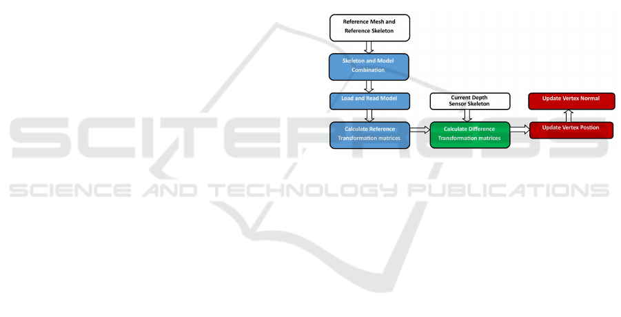
Figure 1: A skeletal wireframe model animation requires
several processing steps: 1) one-time calculation on the
CPU (blue), 2) dynamic recurring CPU calculations (green)
and 3) hardware intensive GPU calculations (red).
The animation of a wireframe model oriented on
skeleton points requires computional extensive imple-
mentation steps. Since real-time capability must be
guaranteed, the visualisation process cannot only be
realised on the CPU, but must also include the GPU.
Figure 1 illustrates all necessary steps. In each indi-
vidual step, calculations are carried out, which must
be available in the following section in order to ensure
proper skeletal wireframe model animation. Some
of these calculations are performed only once on the
CPU (the calculation of the static reference transfor-
mations of the loaded skeleton model), others are also
performed on the CPU (the calculation of the dy-
namic difference transformation between the current
and static skeleton model) at each current incoming
skeleton change and others are performed on the GPU
(the calculation of the new vertex positions of the tri-
angle mesh and the corresponding normal) at each in-
dividual render step.
Individual Avatar Skeletal based Animation Feedback for Assisted Motion Control
207

3.1 Static Animation Calculation
First the reference skeleton system is connected to the
reference mesh. This is performed once on the CPU.
In order to make the connection, the model is first
rigged and then skinned (Crespo, 2003).
The purpose of rigging is to create a duplicate cor-
responding to the existing extraction skeleton. This
duplicate is scaled and shifted so that it fits exactly
to the existing mesh. There are several 3D mod-
eling tools on the market that are able to perform
this. Thus a bone hierarchy is created with Blender
(Blain, 2019), which connects all associated child
bones starting from a root bone in order to adapt the
skeletal system.
The following skinning of the mesh includes the
assignment of bones involved in the animation to a
vertex describing the mesh surface. The forces of at-
traction of the bones to the vertex are calculated. The
forces are very large when the vertex is positioned in
the immediate vicinity of the bone and decrease with
increasing distance. A nearby bone has a high force
of attraction on the vertex and other distant bones. In
the proposed assistance system, up to eight possible
participation bones are noted.
The rigged skinned model available in Blender
is then exported to our visualisation system with all
available vertex data. The transformation matrices of
the reference skeleton system are as well calculated.
However, each bone has its own bone coordinate sys-
tem. For the animation, however, we need these single
values in relation to the root coordinate system and
its transformation matrix m
r
, which is the only one
already statically adopted. For this purpose, all ma-
trices of the chained children’s bones are multiplied
down to the root bone and the new reference system
of the bone under consideration is created. For the
complete iteration of the entire skeleton, the depth of
the adjacent bone d of each bone b has to be consid-
ered first.
b[i].m
r
= m
r
· b[i].m
r
fori = 0, ..., d (1)
The matrices m
r
of each bone that are now available
are required for the difference adjustment to the dy-
namically occurring skeletal changes that result from
movement of the test person and are saved for the en-
tire duration of the training (Huey, 2014). These root
matrices m
r
must be updated if the reference wire-
frame model or the reference skeleton model changes.
In these cases, the vertex attribute coupling is no
longer suitable because the corresponding geometry
has been modified.
3.2 Dynamic Animation Calculation
When the test person moves, the depth sensor extracts
a new skeleton. This is compared with the previously
calculated reference system in subsection 3.1 describ-
ing the standard position and its motion difference
(Mukundan, 2012) is determined.
Since these calculations only refer to the bone sys-
tem to be described by the sparse skeleton data in
which each individual bone is described by a start and
end point, they can also be performed dynamically on
the CPU without a noticeable loss of performance be-
ing measurable. Therefore the skeletal connection of
the incoming bone data has to be known in order to
recalculate the reference. For each incoming bone, its
start point s and end point e are set. For the required
updated 3D transformation matrices m
t
of the bone,
the vector difference es
∆
and their length l are deter-
mined. A transformed direction vector td of the bone
is then calculated.
x
y
z
es
∆
=
x
y
z
e
−
x
y
z
s
(2)
x
y
z
td
=
x
y
z
es
∆
·
1
l
(3)
The rotation between the static reference delta res
∆
,
i.e. the difference between the end vector and the start
vector of the reference skeleton from capital 3.1 and
the now available transformation direction td is de-
scribed by the quaternion q (Beutelspacher, 2010).
q = rot
x
y
z
res
∆
,
x
y
z
td
(4)
The final transformation matrix m
f
of the bone results
from the transformation of the quaternion into a 3x3
matrix.
3.3 Hardware-accelerated Dynamic
Animation Calculation
The surface animation of the wireframe model con-
nected to the skeleton is calculated with a shader pro-
gram on the GPU to ensure real-time capability. Due
to its architecture, the GPU is able to execute graphics
operations much faster than the less specialised CPU.
The following calculation steps must be applied
per frame (Movania, 2013) for each individual surface
point, i.e. each individual vertex of the entire grid, in
order to realise the correct animation per render step.
VISAPP 2020 - 15th International Conference on Computer Vision Theory and Applications
208

The first step is to transfer the index values b
j
of
the bones important for the vertex to the shader, which
are already provided in the subsection 3.1. It can be
computed how many bone weights act on the consid-
ered vertex. By iterating over the array it can be deter-
mined which bone influences the vertex. Since there
are eight possible influencing segments in the system,
this interval is examined to determine the number of
weights w
c
.
w
c
=
7
∑
i=0
b
j
[i]
(
+0 if 255
+1 otherwise
(5)
In addition, the total weight w
s
, which denotes the in-
dividual bones involved in the vertex, is calculated by
iteratively adding up the individual weight values. For
this aim, the exact weight arrays b
w
from subsection
3.1 in the shader are needed.
w
s
=
w
c
∑
i=0
b
w
[i] (6)
Consequently, the number of weights w
c
has been de-
termined, an iteration of the next steps for the new
vertex position is carried out.
The index i
b
of the useful bone is derived from the
array of available bone indices.
i
b
= b
j
[i] fori = 0, ..., w
c
(7)
The determination of the position transformation vec-
tor p
∆
is the difference between the considered static
vertex position p and the static starting point b
rsp
,
the associated reference bone segment resulting from
the iteration, which was previously forwarded to the
shader.
x
y
z
p
∆
=
x
y
z
p
−
x
y
z
b
rsp
[i
b
]
(8)
When the current transformation matrix m
f
of the
bone determined dynamically on the CPU is multi-
plied by the position transformation vector p
∆
, the
current rotation displacement vector r
∆
of the vertex
results.
x
y
z
r
∆
=
a
11
··· a
13
.
.
.
.
.
.
.
.
.
a
31
··· a
33
m
f
[i
b
]
·
x
y
z
p∆
(9)
For the final determination of the new vertex position
a weight factor f
w
is needed which results from the
division of the current weight value b
w
and the total
weight of the bones w
s
.
f
w
=
b
w
[i]
w
s
for(i = 0, ..., w
i
) (10)
The starting point of the current proband skeleton
bone b
sp
is added to the rotation displacement vec-
tor r
∆
and the result is multiplied by the weight factor
f
w
. The sum of all iteration steps of the skeletal bones
involved is the new position p
n
of the vector shifted
by the skeleton animation to be rendered.
x
y
z
p
n
=
w
c
∑
i=0
x
y
z
b
sp
[i
b
]
+
x
y
z
r∆
w
(11)
For the new normal n
n
the procedure is relatively sim-
ilar. Here, too, the single iterations are summarized.
Thereby the single values result from the multiplica-
tion of the current dynamic bone transformation ma-
trix m
f
, the vertex normal n and the weight factor f
w
.
The normal n
n
necessary for the illumination is trans-
fered to the next vertex colouring shader step for pro-
cessing.
x
y
z
n
n
=
w
c
∑
i=0
m
f
[i
b
]
·
x
y
z
n
· f
w
(12)
4 COLOURATION OF MESH
SEGMENTS
If the assistance system that evaluates the movement
detects an error in the exercise sequence, this refers
to a specific area of the patient’s body. By marking
this body segment in colour, the patient is immedi-
ately aware of where the movement error occurs and
the error can be avoided during the next exercise. The
traffic light colouring, known from road traffic, visu-
alise the patient whether it is an error (red), a warn-
ing (yellow) or whether the procedure was carried out
correctly (green or standard mesh colour).
The sequence of such segmentation colouring is
shown in the Figure 2. The reference mesh and
the corresponding reference skeleton are the start-
ing point for the colour-coded error display. After
the skeleton and the 3D avatar have been connected,
the segmentation of the skeletonised surface can take
place. Subsequently, the current motion errors occur-
ring on the skeleton can be displayed directly on the
mesh. The error attributes are dynamically updated
Individual Avatar Skeletal based Animation Feedback for Assisted Motion Control
209
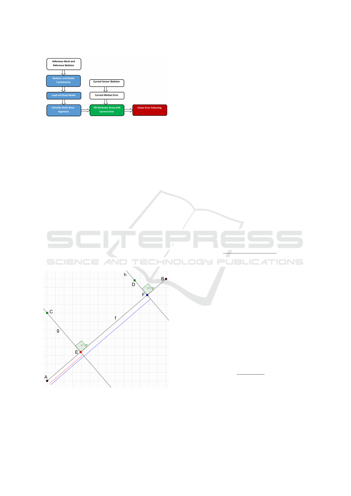
Figure 2: The segmented linear error colouring is calculated
statically (blue) and dynamically (green) on the CPU and
passed as a vertex attribute to the fast GPU (red).
and forwarded to the shader units (Crespo, 2003) of
the processing chain.
4.1 Bone Bound Mesh Segmentation
The motion errors are detected by the assistance sys-
tem by comparing the instantaneous skeletal motion
with the position of a reference skeleton. In order
to display the deviations on the mesh, the bone posi-
tion on the surface grid of the mesh have to be closed.
Therefore, each surface vertex is be assigned exactly
the bone that is selected as the main bone for it on the
basis of the distance and the corresponding attraction
weight. The data provided by the reference system is
sufficient to perform a single segmentation directly on
the CPU. The resulting data can be used with dynamic
processes, since the mesh does not re-segment during
animation.
Figure 3: The linear segmentation of the bone AB by the
perpendicular foot point calculation of F and H through the
surface vertices D and F.
The two points C and D in Figure 3 are surface ver-
tices of the 3D avatar. The standard Gaussian dis-
tribution of weights corresponding to the principal
weight in the middle of the bone is to be converted
into a linear distribution over the bone line so that
the colouration can be performed evenly from bone
beginning to bone end, i.e. from A to B. Once all
nodes v of the wireframe model have been processed
and all required data extracted, the bone index b
imax
of
the largest weight value b
wmax
is determined for each
node from the corresponding field b
w
to calculate the
main bone of the node.
b
wmax
=
7
∑
i=0
max(b
w
[i]) foreach(v) (13)
b
imax
= i if b
wmax
(14)
C and D are thus assigned to the bone AB. After the
involved vertices have been defined, the perpendicular
lines g and h are dropped onto the bone line AB and
their intersections E and F are calculated.
x
y
z
AB
=
x
y
z
B
−
x
y
z
A
(15)
v
u
=
(C.x − A.x) · AB.x
(C.y − A.y) · AB.y
(C.z − A.z) · AB.z
(16)
u =
v
u
.x + v
u
.y + v
u
.z
AB.x
2
+ AB.y
2
+ AB.z
2
(17)
x
y
z
E
=
A.x + u · AB.x
A.y + u · AB.y
A.z + u · AB.z
(18)
For the above equations (17) and (18) the intersection
vector E is calculated as an example. For F and its
reference point D as well as for all other vertices be-
longing to the bone this intersection point has to be
determined as well.
The quotient between the length of the subvector
AE and the length of the total vector AB gives the per-
centage share of AE with respect to AB, i.e. exactly
the desired linear factor f
s
for the desired segmenta-
tion. The proportion of AE (red) to the total distance
AB is less than that of AF (blue).
f
s
=
length(AD)
length(AB)
(19)
Using the factor f
s
the reference mesh can be coloured
segment by segment. In order to do this, a four-
dimensional vector is assigned to each surface vertex
of the mesh, which contains its colour.
VISAPP 2020 - 15th International Conference on Computer Vision Theory and Applications
210
x
y
z
a
colour
=
f
w
0.0
1.0 − f
w
1.0
(20)
Using the example of this red-blue colouring ap-
proach, the following results are obtained for linear
segment colouring for various freely selectable grid
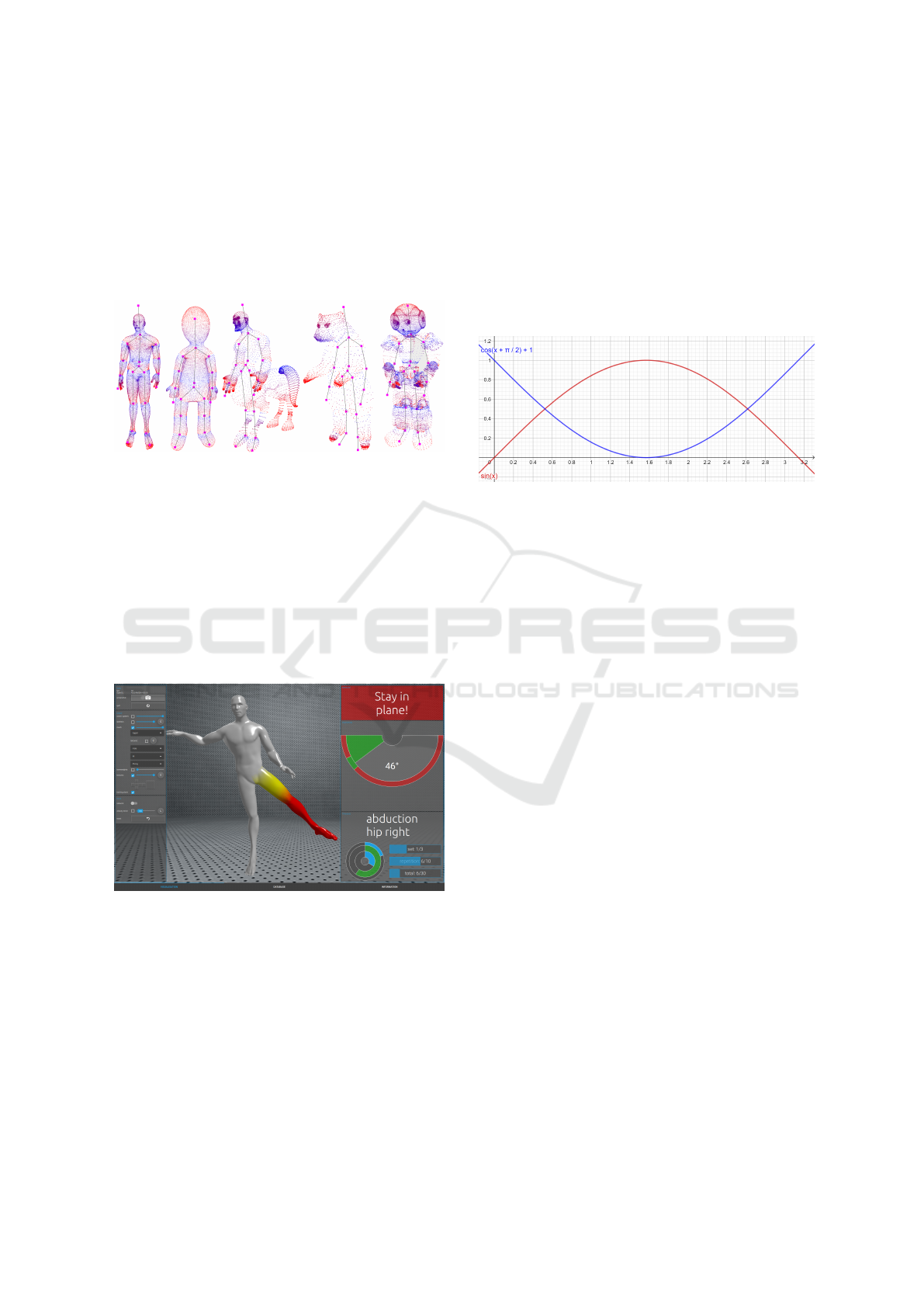
models.
Figure 4: Linear staining of bone segments for various in-
dividual wire mesh models.
4.2 Segmented Motion Error Coloring
Once the bone segmentation has been calculated, it
can be used to clearly represent a movement error in
the animated model. Since the entire surface has to
be considered, the graphic pipline is dependent on the
colour-processing layer of the GPU. Thus, the real-
time requirement can also be fulfilled during the pro-
cessing of 3D vertices.
Figure 5: A real-time animated wireframe model in MTT
that colours the error segments.
This is converted in the visualisation unit into a
shader attribute, which will be filled with three sub-
segments per skeletal bone which hold a suitable
colour for the visualisation. Thus, a bone can have
three different colours if it supports the error estima-
tion and the entire skeleton is indexed coloured. Fig-
ure 5 shows a linear colouration for a deviation de-
tected on the right leg.
For the realisation of the visualisation, each bone
of the skeletal system used is iterated and checked
whether there is an error for this index in one of the
three segments s
i
of the error attribute v
e
. If this is
the case, the desired colour and its intensity are calcu-
lated.
This is carried out by using the static percentage
factor of the linear weight distribution f
s
calculated
on the CPU in subsection 4.1, to determine in which
segment area of the bone the vertex can be localised.
The value is now used to calculate the vertex colour
v
c
over a sine-cosine-distribution.
Figure 6: The colouration of the vertex consists of the nor-
malised sum of cosine and sine values, which are deter-
mined by the distance factor f
w
.
It is distinguished whether the factor is above or be-
low the value 0.5 in order to determine the correct
cosine fraction for the first summand. In the Figure
6 this function is marked by the blue, shifted cosine
curve.
v
c
= (1.0 − cos(Π/2 + (− f
w
∗ Π)))· v
e
[s
i
] (21)
v
c
= (1.0 + cos(Π + (2(− f
w
∗ Π/2)))· v
e
[s
i
] (22)
If f
s
< 0.5 the equation 21 is used in any other case
equation 22.
If the first summand is determined, the second
sinusoidal summand, in Figure 6 the red curve, is
calculated for the normalized sum and added to the
previous one to determine the final three-dimensional
colour vector.
v
c
= sin( f
w
∗ Π) · v
e
[s
i
] + v
c
(23)
This sum always generates values between 0 to 1
and determines the three RGB values of the colour
vector that estimates how the colour value is com-
posed for the position vector.
5 RESULTS AND DISCUSSION
An assistance system has been developed to help
MTT patients to perform their movements in an or-
derly and targeted manner. The core of the system
Individual Avatar Skeletal based Animation Feedback for Assisted Motion Control
211
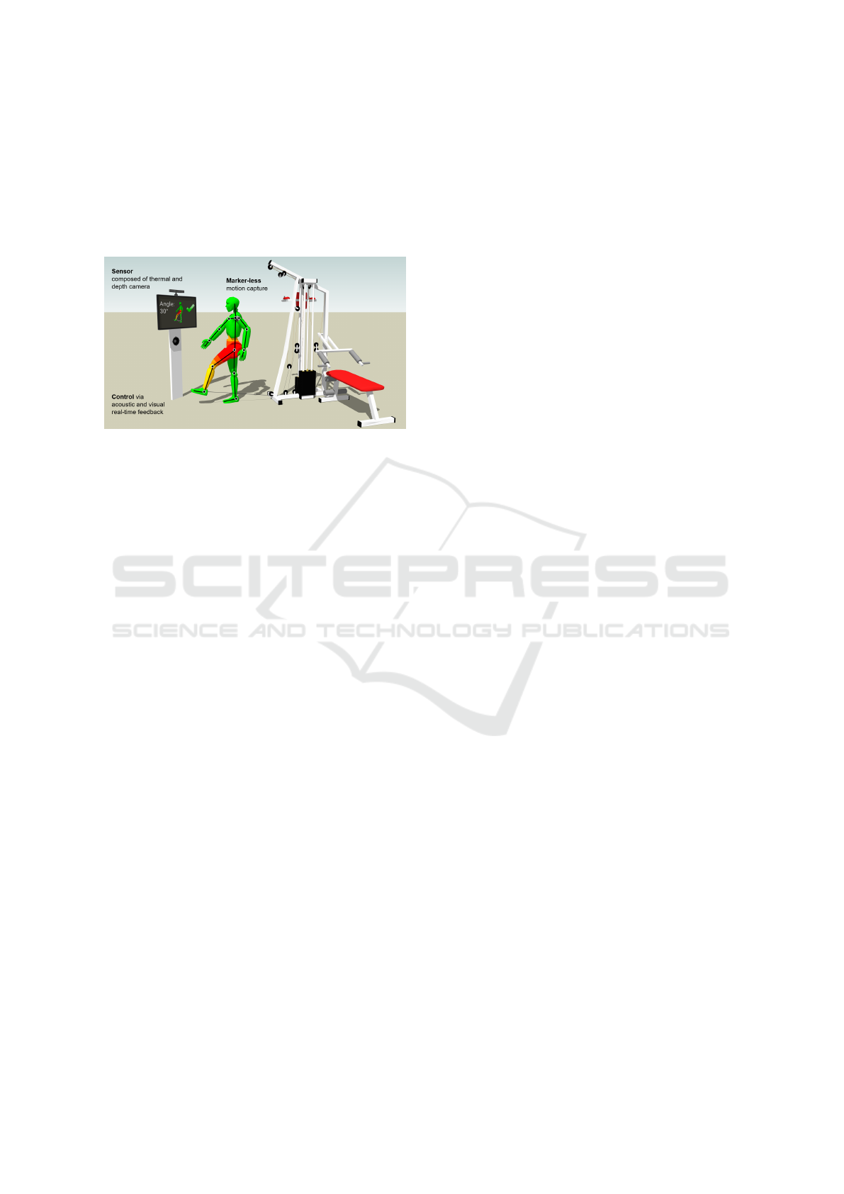
is the rope pull on which the movements are carried
out. The patient stands in front of a depth sensor,
which extracts the skeletal data and performs a mo-
tion analysis. The results are visualised in real time
on a display belonging to the assistance system. Both
the coloured animation mesh and the textual hints as-
sociated with the movement are visualised.
Figure 7: The design of the assistance system for the study
consists of a wire rope hoist, depth sensor and a display
monitor (J. Richter, 2017).
The C++ standardised toolkit Qt was used for
the realisation of the assistence system. This frame-
work is characterised by increased flexibility in GUI
creation. Qt has the declarative programming lan-
guage QML, whereby individual GUIs can be cre-
ated with the help of a JSON-based metalanguage.
During the implementation of the visual feedback, a
real-time realisation was a particularly noteworthy as-
pect. Since the patients had to be informed immedi-
ately about their wrong movements, which should al-
ready avoid their error during the next movement ex-
ecution, a GLSL shader implementation became un-
avoidable. Even meshes beyond the 100,000 individ-
ual vertices could be displayed in real time. Also
the animation with different single models and the
change of the models was realised. Thus the motiva-
tion of the patients could be increased, because they
preferred different animation models. Since OpenGL
was already used for the animation, the coloration of
the bone segments could be implemented in a further
GLSL shader step on the fragment side. This im-
plementation meets the necessary real-time require-
ments, which require a frame rate of 25 frames per
second, and rounds off the desired assistance system
in terms of information density. For the application’s
humanoid standard mesh, which requires 146754 ver-
tices to be rendered per visualization step, the frame
rate is 60 frames per second, where one AMD ATI
Radeon RX Vega M GL graphics card is used.
A user acceptance study was conducted to test the
system in clinical practice. The aim was to investi-
gate how the visual feedback system encouraged and
motivated patients to perform the movements to be
trained properly and how the visual design was per-
ceived. For this purpose, the assistance system was
tested in a clinical facility, for patients with a new hip
implant. 15 subjects completed a three-week rehabil-
itation program and trained with the assistance sys-
tem under therapeutic supervision. Patients were then
asked to complete a standardised questionnaire with
twelve questions and five possible answers.
In the survey, the system was predominantly as-
sessed positively. The evaluation of the movement
feedback, which was important for the question of the
paper, and the indications of an autocorrection were
mostly understandable and helpful (Nitzsche, 2018).
In addition, the error frequencies were evaluated
over the duration of the therapy. The aim was to
determine whether the patient’s movements could be
improved during the training period with the help of
the assistance system. This also shows that the error
rate monitored by the assistance system decreased by
more than 50% (L
¨
osch, 2019).
6 CONCLUSION AND FUTURE
WORK
A visual feedback was created for the movement ther-
apy, in which it is possible to select an individual
avatar for the display. The movements were anal-
ysed and evaluated. Errors were coloured according
to their importance in traffic light colours on the previ-
ously calculated bone segments. This allows patients
to see immediately where the error occurred. In order
to evaluate the assisted therapy system, a user study
was carried out with 15 subjects. The results indicates
a high user acceptance. The independent evaluation
of the recorded training results showed a noticeable
gain in health-promoting movements.
In future the integration of real scanned individual
characters would promote immersion. Of course, the
creation of the models would have to be feasible as a
sideline and without too much time expenditure.
The monitoring of the control should also extend
to other body regions. Both the hands and the face
could be integrated into the motion monitoring. In ad-
dition, an automatic system to record reference move-
ments have to be implemented. Thereby, the thera-
pists could store a new motion sequence at any time.
The integration of the complete system into a vir-
tual reality environment would have an increased im-
mersion. The limitation that is associated with a
fixed location feedback system would be abolished.
It would no longer be necessary to realign the display
device for body rotated exercise changes.
VISAPP 2020 - 15th International Conference on Computer Vision Theory and Applications
212

REFERENCES
Beutelspacher, A. (2010). Lineare Algebra.
Vieweg+Teubner Verlag, Wiesbaden, 7th edition.
Blain, J. (2019). The Complete Guide to Blender Graph-
ics: Computer Modeling and Animation. Taylor and
Francis Ltd, London, 5th edition.
Crespo, D. S. (2003). Core Techniques and Algorithms
in Game Programming. New Riders Publishing, San
Francisco, 1st edition.
E. Vellosso, A. B. and Gellersen, H. (2013). Motionma:
motion modelling and analysis by demonstration. In
CHI ’13, Proceedings of the SIGCHI Conference on
Human Factors in Computing Systems. ACM.
Huey, L. B. (2014). Paper templates. In Example-based
Rigging and Real-time Animation of Characters with
Linear Skinning Models. ETD Collection.
J. Richter, C. W. and Hirtz, G. (2017). Motion error classifi-
cation for assisted physical therapy - a novel approach
using incremental dynamic time warping and nor-
malised hierarchical skeleton joint data. In ICPRAM
2017. Semantic Scholar.
J. Richter, C. W. and Hirtz, G. (2017). Assisted Motion
Control in Therapy Environments Using Smart Sen-
sor Technology: Challenges and Opportunities. In 9.
AAL-Kongress. Ambient Assisted Living.
Kwon, D. Y. and Gross, M. (2005). Combining body sen-
sors and visual sensors for motion training. In ACE
’05, Proceedings of the 2005 ACM SIGCHI Interna-
tional Conference on Advances in computer entertain-
ment technology. ACM.
L
¨
osch, C. (2019). Paper templates. In Validation of an as-
sistance system for motion analysis. German Journal
of Sports Medicine.
Movania, M. M. (2013). OpenGL Development Cookbook.
Packt Publishing, Birmingham, 1st edition.
Mukundan, R. (2012). Advanced Methods in Computer
Graphics: With examples in OpenGL. Springer,
Berlin, 2nd edition.
Nitzsche, N. (2018). Assistierte Bewegungskontrolle in der
Rehabilitation durch intelligente Sensortechnologie.
readbox unipress, M
¨
unster, 1st edition.
Smith, M. (2015). Unity 5.x Cookbook: More than 100 so-
lutions to build amazing 2D and 3D games with Unity.
Packt Publishing, Birmingham, 1st edition.
Wolff, D. (2018). OpenGL 4 Shading Language Codebook.
Packt Publishing, Birmingham, 3nd edition.
Zhao, W. (2014). Combining body sensors and visual sen-
sors for motion training. In 5th IEEE International
Conference on Software Engineering and Service Sci-
ence. IEEE.
Individual Avatar Skeletal based Animation Feedback for Assisted Motion Control
213
