
Expanded Virtual Puppeteering
Luiz Velho
1
and Bernard Lupiac
2
1
IMPA - Instituto de Matematica Pura e Aplicada, Brazil
2
PUC-Rio - Universidade Catolica Rio de Janeiro, Brazil
Keywords:
Virtual Reality, Digital Puppetry, Artistic Performance, Animation.
Abstract:
This work proposes a framework for digital puppeteering performances, using solely the performer’s bare
hands. The framework relies on Unity as a base, and hand information is captured from a Leap Motion device.
The performer employs a gesture interaction system and precise hand movements to manipulate the puppet in
a number of different manners. It is then possible for the audience to view the puppet directly in a big screen,
or using virtual or augmented reality headsets, which allows rich interactions.
1 CONTEXT AND MOTIVATION
New Media is a phenomenon where recent develop-
ments in technology are integrated with traditional
types of media. There is a range of mediums con-
cerned by it, like for example books, movies, mu-
seum exhibits and plays. These past few years,
new paradigms of interaction and visualization have
emerged, with the resurgence of virtual and aug-
mented reality, and markerless hand and body inter-
action. Since their emergence is very recent, there is
still much to explore about them and the possibilities
they will bring.
This work proposes a framework for digital pup-
peteering performances, where the performer uses
only his or her bare hands. The program uses the
Unity framework, and hand related information is
captured with a Leap Motion device. The aim of this
work is to preserve the expressiveness and know-how
of classic puppeteering, while at the same time, to
look at it in a different perspective with the help of
the aforementioned advances in technology.
The paper is structured in the following manner:
Section 2 will give a brief history of the development
of digital puppetry in academia and in the show and
film business. Following it, section 3 will give an
overview of all the different ways in which the pup-
pet can be moved and the reasons why they will or
won’t be used in our work. Afterwards, section 4
will describe in a detailed manner all the modules im-
plemented in this framework. Then, section 5 will
explain the necessary process to generalize this pro-
gram, so it can be used in many different contexts.
Thereafter, Section 6 shows the different types of pos-
sible visualizations. Finally, Section 7 gives an exam-
ple where this framework is used by artists to do a
small performance.
2 BACKGROUND, HISTORY AND
RELATED WORKS
Digital puppetry isn’t a new concept by any means.
In the early sixties, Lee Harrison III used body suits
with potentiometers, animating a 3D model in a CRT
screen.
A few decades later, around 1988, digital pup-
peteering gained the attention of the general public
with the help of two projects: Waldo C. Graphic and
Mike Normal.
Waldo C. Graphic is a character on the Muppet’s
show The Jim Henson Hour. Waldo is an entirely
computer generated puppet, controlled by a single
puppeteer with a big contraption.
Mike Normal, created by Brad DeGraf, was un-
veiled at the 1988 SIGGRAPH conference, and was
the first live performance of a digital character. It al-
lowed a performer to control many parameters on its
face, with real-time interpolation between them.
In 1994, in Charleville-M
´
ezi
`
eres, a significant
event also took place: e-Motion Capture. It united
researchers in the field of Computer Graphics and per-
formers from around the world to experiment the dif-
ferent technologies developed for virtual puppeteer-
ing up to that date.
Velho, L. and Lupiac, B.
Expanded Virtual Puppeteering.
DOI: 10.5220/0008917700610070
In Proceedings of the 15th International Joint Conference on Computer Vision, Imaging and Computer Graphics Theory and Applications (VISIGRAPP 2020) - Volume 1: GRAPP, pages
61-70
ISBN: 978-989-758-402-2; ISSN: 2184-4321
Copyright
c
2022 by SCITEPRESS – Science and Technology Publications, Lda. All rights reserved
61

A small number of other digital puppets were de-
veloped in the next few years. Among them are Mat
the Ghost, who appeared daily on French national
television for years, and Moxy, part of a Cartoon Net-
works show, created by Brad DeGraf.
In the same way there wasn’t much advancement
from the early sixties until late eighties, this field
wasn’t very active from mid nineties until mid 2010s.
This resurgence was caused by recent advances in
technology that allowed to overcome longstanding
problems in the field.
However, there were still attempts to adapt 2000s
technology to digital puppeteering. The main devices
used during that time were the dataglove, a very un-
wieldy and expensive device. Some attempts were
also made to use accelerators, with the controllers
provided with the Wii video-game console(Shiratori
and Hodgins, 2008).
What made the current developments in this field
possible were advancements in computer vision and
the vulgarization of depth-finding cameras, in prod-
ucts like Microsoft’s Kinect, the Leap Motion and
eventually smartphones.
In Seth Hunter’s and Pattie Maes’ work(Hunter
and Maes, 2013), a number of methods for perform-
ing digital puppeteering using green screens and com-
puter vision are described. Lins’ and Marroquin’s
work(Souza et al., 2015) proposes a way to control
a puppet’s walking motion by using the Kinect and
trackers at the tip of two fingers. More recently, An-
deregg et al. present a way to manipulate a puppet in
an augmented reality environment by using a smart-
phone’s sensors and screen(Anderegg et al., 2018).
Around that period, some commercial products
were developed for digital puppeteering. Puppet Pa-
rade uses the Kinect to allow manipulating multiple
puppets and let the audience interact with them at the
same time. Marionette Zoo (Botond G
´
abor et al.,
2014) lets users control a set of puppets using the
Leap Motion and a physics-based system with strings.
Some research involving puppet manipulation
using the Leap Motion already exists. Oshita
et al.(Oshita et al., 2013) propose a manipulation
scheme inspired from a real puppet manipulation
crossbar. It allows a user to manipulate arms, legs
and trunk simultaneously by using both hands’ posi-
tions, rotations and the stretching of fingers. Other
approaches, such as (Ciccone et al., 2017), have also
used Leap devices for puppet animation.
Leite’s and Orvalho’s work(Leite and Orvalho,
2017) describe three separate puppet manipulation
modes: a first one that manipulates many different
facial features of a puppet’s head, such as eyes, eye-
brows and mouth. A second that moves the puppet
with physics, where the performer’s hand position and
rotation corresponds to the puppet’s head position and
rotation. The last mode is a junction of the first two:
one hand controls the puppet’s head position and fa-
cial features while the rest of its body is moved by the
physics system. In addition to that, the remaining free
hand is used to manipulate one of the puppet’s own
hands.
Our work proposes a framework that uses a new
approach to puppet manipulation. Instead of hav-
ing all possible movements mapped to different parts
of the hand, we use a gesture-based system that al-
lows switching between different contexts in run-
time, where each context corresponds to a different
type of movement. This results in more straightfor-
ward and precise controls, since the whole range of
both hands’ movement is available to every type of
movement. Other important advantages this system
brings is the ability to support an extensive amount of
movement types simultaneously, and the lack of diffi-
culty associated with developing a new one. In addi-
tion to this, our framework addresses other challenges
associated with puppeteering performances, such as
a way for a director to control different cameras and
visualization by the audience in a screen, virtual or
augmented reality.
3 PUPPET MOVEMENT
PARADIGMS
This section shows all the explored forms of move-
ment that can be used to manipulate the puppet. It
then explains their advantages and disadvantages for
the purpose of this work. Based on that, the overall
suitability of each one is evaluated.
The fundamentals of our puppet movement con-
trol rely on three aspects: i) blended animations; ii)
inverse kinematics; and iii) physically-based simu-
lation. All these three features are fully supported
by modern game engines such as Unreal and Unity,
which we have chosen for the implementation of our
system.
3.1 Animations
Animations are pre-recorded sets of movement that
are applied to a model over a finite amount of time.
They can either record the position of every vertex
or bone in every frame, or just keep a few sets of
recorded positions (called keyframes) and interpolate
between them.
Movements using animations are very well inte-
grated in Unity because of their widespread use in
GRAPP 2020 - 15th International Conference on Computer Graphics Theory and Applications
62

video-games. It also means that there are many open
license animations available to test and develop, espe-
cially for humanoid models.
With animations, it is possible to perform many
complex and varied types of movements very eas-
ily. With a simple gesture, the puppet can perform
a dance, make a basketball move or climb a wall.
On the other hand, because of their repetitive na-
ture, animations can end up limiting the amount of
expression a performer can infuse into a marionette.
However, this is a problem that can be avoided by us-
ing methods like blending between two animations, or
by using Unity’s Blendtree system (that blends more
than two animations by using different variables). In
this way, the performer will be able to control a hand-
ful of parameters that will allow him to determine, for
example, how high the puppet will jump or how bad
he will fall after jumping.
Animations have been integrated as one of the
movement types used for the puppets. The loco-
motion movement mode explained in Section 4.2.4,
for example, uses a Blendtree to interpolate between
walking, running and turning. The jump movement
mode detailed in Section 4.2.5 uses simple animations
played in sequence.
3.2 Inverse Kinematics
Inverse Kinematics (IK) is a process that receives a
few simple inputs, and determines the position and
rotation of a set of bones. It will, for example, receive
the position and the rotation of the wrist of a charac-
ter, and in turn determine the positions and rotation
of the forearm and upper arm bones. An extensive
survey of this technology is presented by Aristidou et
al.(Aristidou et al., 2018).
By allowing the performer to do a range of addi-
tional movements with precision, Inverse Kinematics
adds a layer of flexibility and expressiveness to the
puppet. On top of that, they can be used in conjunc-
tion with classic animation, by using masks. With this
feature, it is possible to choose which bones will use
the animation and which will use Inverse Kinematics.
Our program uses Unity’s Inverse Kinematics sys-
tem to perform its head and arm movements. As ex-
plained in Section 3, IK is used rotate the head in the
direction we want while respecting constraints that
make this movement look natural. The arms move-
ment mode, described in Section 4.2.3, uses the palm
position and wrist rotation given by the Leap Motion
to determine the configuration of all other bones in
the arm.
3.3 Physically based Animation
Physically based animation makes an object perform
realistic movement by using physics simulation. Sim-
ulating physics with mathematical equations has been
a topic of research for centuries, and because of that,
most of the theory behind what we need for this work
has been around for a while. Yet to perform these
simulations in real-time in a stable and aesthetic fash-
ion is a whole different matter. It is still possible with
a lot of loose simplifications, but it can still behave
unexpectedly.
Theoretically, physically-based animations would
let a puppeteer perform any and every movement he
desires. It would also allow very interesting interac-
tions with the scenario, like making the puppet stum-
ble on a rock or be blown away by the wind. However,
trying to use this type of movement with in practice
reveals a lot of challenges (Bousquet, 2015).
Physics systems can be very unstable, especially
when many bones and ropes are being used. This hap-
pens because there is a considerable number of con-
straints that need to be satisfied, which increases the
likelihood that something unexpected occurs, given
the number of approximations made. This can be mit-
igated to a certain degree by fine-tuning and configur-
ing the used model. However, this is a tiresome trial-
and-error procedure that also goes against the philos-
ophy of our work since it makes the framework less
agnostic to the model used.
In addition, the biggest disadvantage that comes
with this type of movement is the limitation of the
hand as a controller. It is a very difficult task to make
complex movements with this system because of all
the degrees of freedom involved. Waiving is trivial for
example, but walking or jumping in a realistic manner
becomes almost impossible.
It is then no surprise that in real-life puppetry, con-
trols that consist of simply attaching strings to the
puppet’s limbs are almost non-existent. They most
commonly use a set of complex mechanisms that al-
low the performer to reproduce realistic movements
while pulling a few strings at a time.
With this in mind, we implemented two physi-
cal simulation systems as prototypes by using using
Unity’s rigid body simulation:
• One where strings were attached from the tips of
each finger to each different limb. It proved to be
very hard to perform complex movement this way
because of the difficulty of moving fingers inde-
pendently, and their limited range of movement.
• The other resembles a classic method of pup-
peteering called the crossbar. All the strings are
attached to a plane, and the performer would then
Expanded Virtual Puppeteering
63
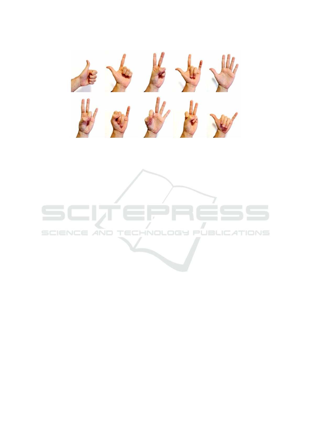
Figure 1: Gesture Set currently used with the gesture recognizer.
change the rotation of said plane with the hand.
Movements turned out to be more reliable and had
an increased range, but the inability to move limbs
independently still made this system limited.
Unfortunately, because of the disadvantages men-
tioned, these two prototypes were discarded.
Finally, we implemented physics simulation in our
system very succesfully by restricting it to collision
detection of the puppet with other objects in the scene
and reaction to external forces.
4 ARCHITECTURE
This section describes the main modules of the pro-
gram: the gesture recognizer, the movement manager
and the network component. It explains in detail how
each of them work and how they communicate with
each other.
4.1 Gesture Recognizer
4.1.1 Motivation
In this program, there is a need for other types of inter-
actions in addition to the manipulation of the puppet.
They are needed for controlling other aspects of the
program, such as changing the puppet’s manipulation
mode, adjusting configuration parameters or resetting
the program.
Because of this, there should be a system in place
that allows the performer to change contexts and send
commands. The most natural way to do this is by
using the performer’s hands since they are being con-
tinually captured by the Leap Motion. To make this
possible, a gesture-based interaction system has been
set up using a gesture recognizer.
A Support-Vector Machine (SVM) has been cho-
sen to implement this gesture recognizer, so it can be
flexible with the gesture it uses while still being accu-
rate.
4.1.2 Implementation
There is a vast literature on the subject of gesture rec-
ognizers for the Leap Motion. This implementation is
based on works from Guilio et al.(Giulio et al., 2014)
and Youchen et al.(Youchen et al., 2017), because of
the level of detail given for feature extraction and the
settings used for the SVM respectively.
From the papers mentioned above, the features
used in this implementation for the classification are:
• The angle of each fingertip relative to the palm.
• Distance of each finger from the center of the
palm.
• Distance of each fingertip from the plane created
by the palm.
• Matrix of distances of all fingertips.
The SVM was implemented using Ac-
cord.NET(Souza et al., 2014), which is a C#
library for machine learning. The settings of the
machine are very similar to the ones described in
Section 5 of Youchen et al.(Youchen et al., 2017). In
short, it is a multi-class SVM, that uses grid-search
to find hyper-parameters C and γ. (See Figure 1 with
the current gesture set used in our system.)
4.1.3 Learning
The different types of gestures the recognizer can
learn aren’t hardcoded in any way. By redoing the
learning routine, any hand gesture can be used in the
program (given the limitations of the Leap Motion as
a sensor).
GRAPP 2020 - 15th International Conference on Computer Graphics Theory and Applications
64
The learning routine consists of capturing the
hand in the desired positions many different times to
build a learning database. Afterwards, all these exam-
ples will be used to determine the SVM.
After the machine is set up, it is serialized and
saved to a file that will be reused by the program from
that point on. Since a file is generated, it is possible to
make backups of previous SVMs and to easily switch
between them.
4.1.4 Result
Once the machine is configured, it is very easy to use.
It works as a function: its only inputs are the features
described in Section 4.1.2, extracted from a hand. The
output is the prediction made by the machine: the ID
of the gesture the machine has recognized, in addition
to some metadata, like the reliability of the prediction.
4.2 Movement Modes
There are four distinct basic movement modes and an
additional idle mode. Each of them allow the per-
former to move the puppet in a different manner. To
navigate between them, it is necessary to use gestures.
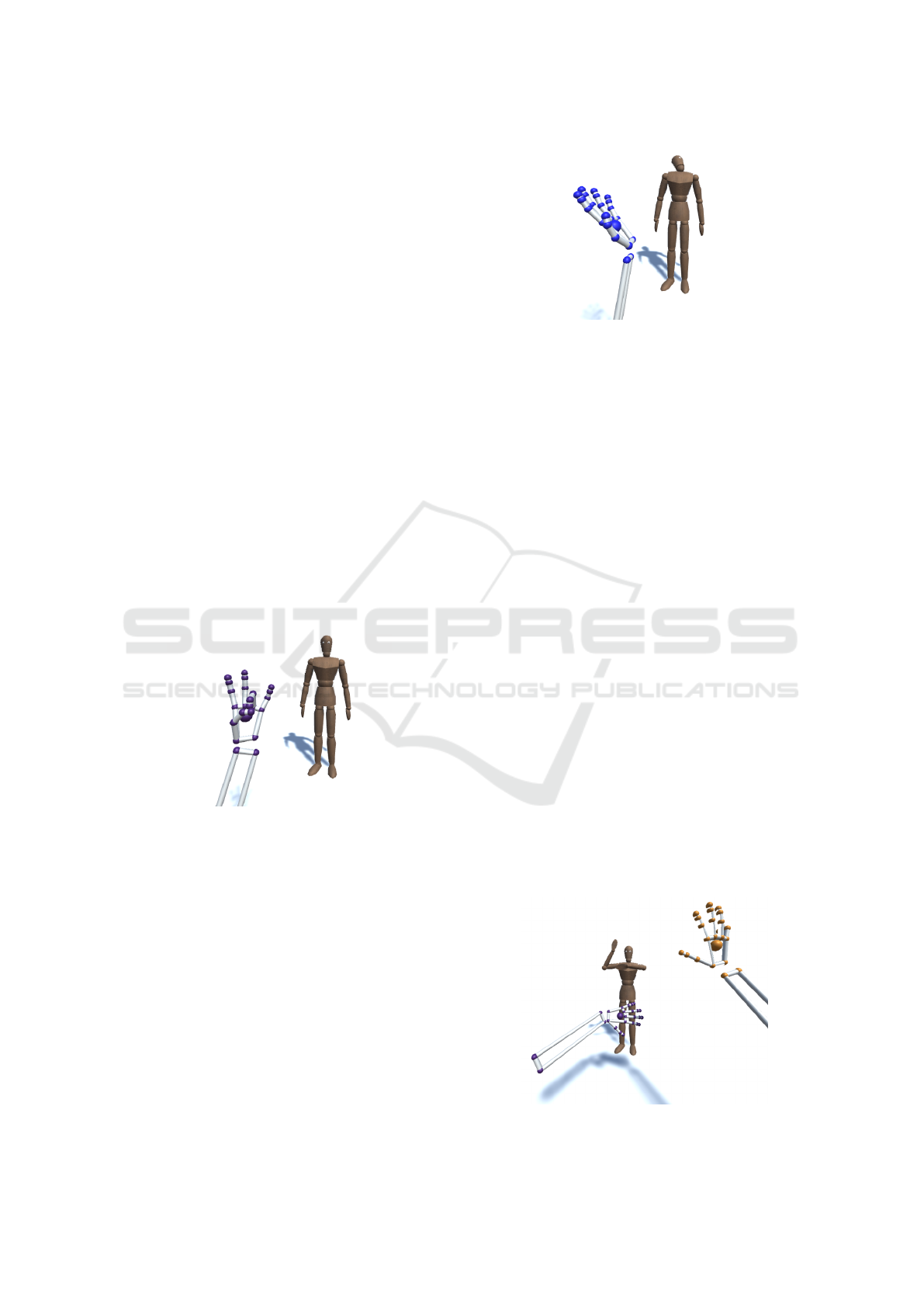
(See an example in Fig. 2)
Figure 2: A gesture made with the Leap Motion.
4.2.1 Idle Mode
The program starts in a “neutral mode”, where the
marionette doesn’t move. To enter in any of the move-
ment modes mentioned below, it is necessary to make
the same specific gesture with both hands at the same
time. Finally, if there is any need to reset the mari-
onette or its position, there is also a reset gesture.
4.2.2 Head Movement
The movement of the head is done using Unity’s in-
verse kinematics (IK) system. The marionette will
look in the same direction as the direction of the palm
detected by Leap Motion. For example, if the palm is
Figure 3: Movement of the marionette’s head.
facing up, the marionette’s head will be looking at the
ceiling. (See Figure 3.)
Since it isn’t always possible to rotate our hands in
every possible direction, a feature was added to allow
to change the default “front” direction of the hand. It
can be used by making a gesture with the right hand
and putting the left hand in the direction that corre-
sponds to its new default.
4.2.3 Arm Movement
It is very straightforward to control the marionette’s
arms: they will move in the same way as the per-
former’s. The arms’ movement also uses Unity’s IK
system, but in a more complex manner. Each arm
has two targets: hand position and rotation. The IK
system will then calculate the marionette’s arm bones
configuration that satisfy the targets given. (See Fig-
ure 4.)
There were experiments made by adding Leap
Motion’s elbow positions to the IK targets. However,
since the Leap Motion doesn’t directly capture the el-
bow positions and instead only estimates them, they
can end up being unstable.
To increase the accuracy of the movement, it is
also necessary to calibrate the length of the arm ac-
cording to the user’s.
During the arm’s movement mode, the head will
either look at the middle point between both hands if
they are approximately at the same height or at the
Figure 4: Arm movements.
Expanded Virtual Puppeteering
65
hand who is raised highest. This adjustment has been
made in order to make the movement more expressive
because it was a bit off-putting for the arms to move
while the head was motionless.
4.2.4 Locomotion
The walking and running controls were subject to
many iterations. The last iteration up to this point is
stable and intuitive.
It works in a similar manner as a joystick in a
video-game. However, instead of receiving x and y
coordinates from an analog stick, it receives the same
information from the Leap Motion.
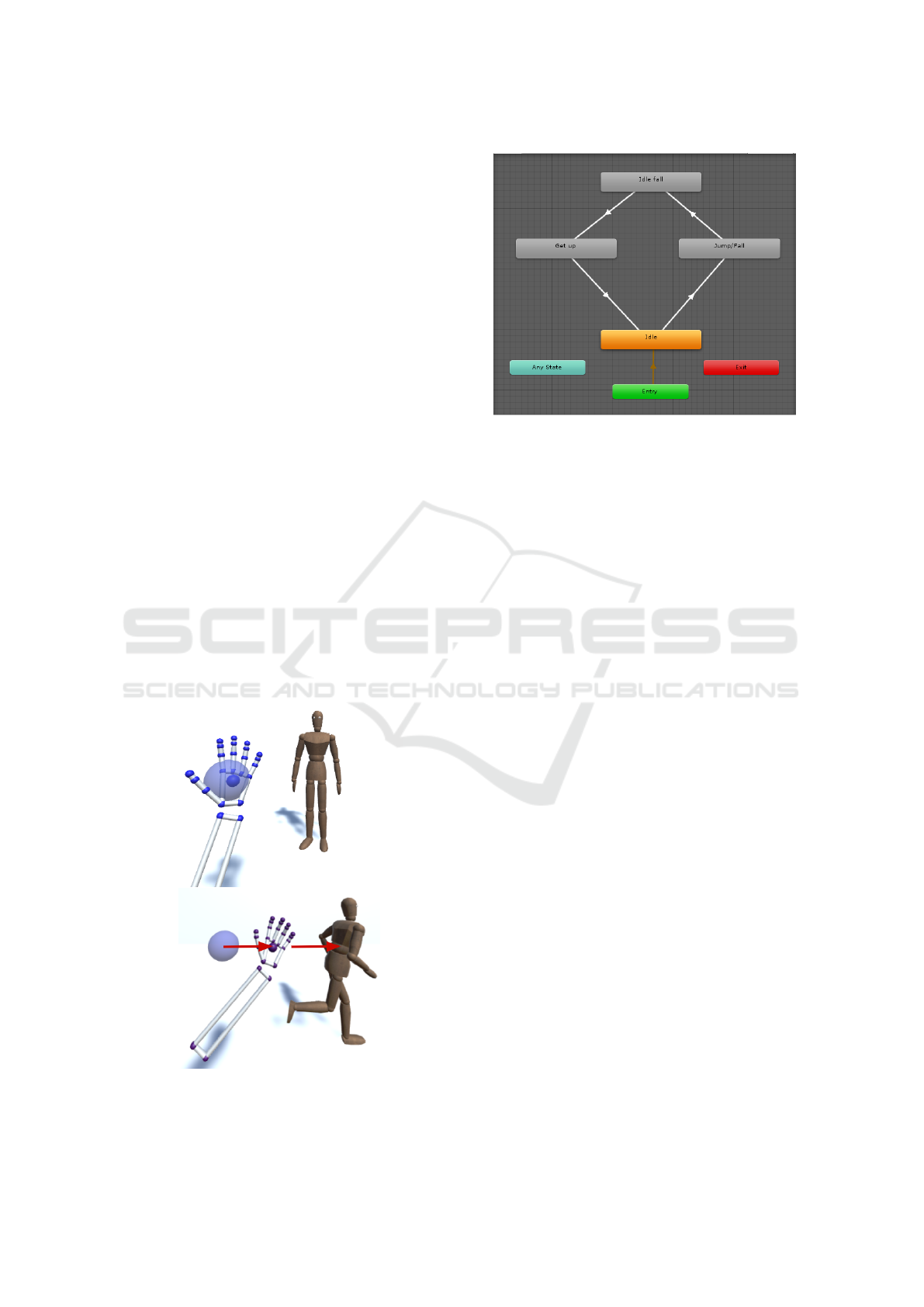
Upon entering the locomotion mode, a sphere will
appear on the position of the hand that will control
the marionette. It stays in the same position, but if
needed, it can be moved by using a gesture with the
other hand.
The sphere acts as a dead-spot for the movement.
While the center of the palm is inside it, the received
x and y inputs will be 0 and the puppet won’t move.
(See Figure 5.)
The sphere also acts as a reference because its cen-
ter is very important to determine the direction and
speed of the movement. They will be calculated using
a vector that starts in the center of the sphere and goes
in the direction of the center of the palm. The vector
is then projected on the xy plane. Its direction deter-
mines the direction of the movement, and its length
determines the intensity of the movement.
Figure 5: The movement mode.
Figure 6: Animation controller used for the jump mode.
4.2.5 Jump
Out of all the movement modes, the jumping mode
is the simplest. It just cycles between three anima-
tions. First, if the speed of the hand in the y direc-
tion is above a threshold (i.e. when the hand is raised
quickly), the jump animation is triggered. Then, the
puppet will stay on the ground, looping an idle anima-
tion. Finally, when the palm is facing up, another an-
imation will be triggered, where the puppet will stand
up and return to its default idle animation. (See Fig-
ure 6.)
4.2.6 Other Movement Types
The movement modes presented above are just a few
examples of what can be done by the puppet. Given
the implementation, adding other movement modes
isn’t a hard task.
4.3 Presentation and Network
There were many reasons that compelled us to sepa-
rate this program into client and host. As discussed in
Section 6, there needs to be at least two instances run-
ning: one for the performer and one for the audience
(or more in the case of Augmented or Virtual Real-
ity), and optionally another one for the director. They
all have different needs and types of interaction, and
putting them all in the same program would make it
unnecessarily cluttered.
4.3.1 Holojam
To perform the networking part of the program, we
used the Holojam SDK (Velho et al., 2017). It meets
all the needs of our program: it can synchronize users
GRAPP 2020 - 15th International Conference on Computer Graphics Theory and Applications
66
Manipulator instance
Host
Movement
Processing
Leap XR
Service
Provider
(external)
Host Hand
States
Leap
Gesture
Recognizer
Holojam Server
Targets IK
Mannequin
Controller
Mannequin
Controller
Movement
Manager
Animator
Puppet
Master
(external)
Hand
Getter
Server
Any instance with
a Mannequin
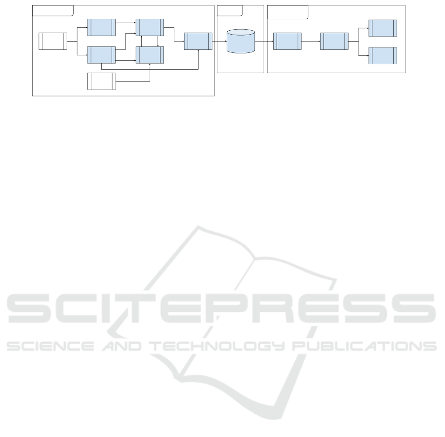
Figure 7: Diagram illustrating class interactions.
positions and their movements in VR, while also al-
lowing other types of data to be sent using Synchro-
nizable Objects.
4.3.2 Synchronizable Objects
In the Holojam SDK, Synchronizable Object are ob-
jects that are constantly broadcast from the host to all
clients in the network. It is possible to send integers,
floats and bits by having a host and a client class.
Our objective is to recreate the Leap’s hand class
from the host in the client. The host then sends all the
important information from its hand (i.e. position, ro-
tation and speed of the palm). With this information,
the client can then recreate a hand that is used by the
other components.
In addition to this, the host sends other informa-
tion, like the detected gesture of each hand. This way,
only the host needs to have gesture recognizer-related
code.
4.4 Class Interactions
All of the modules mentioned above need to have
some degree of communication in order to work. In
order to illustrate this, the diagram in Figure 7 shows
the most important classes in our program, and how
they interact with each other.
Each small rectangle represents a class and the
bigger rectangles containing small ones represent a
GameObjects that has those classes as components.
GameObjects are the base class of Unity’s system.
The single-headed arrow means one class uses an-
other, and a double-headed arrow means both classes
use one another.
As we can see, there are three important GameOb-
jects in this program, HandHost, HandClient and
Mannequin. Because of the networking component, a
HandHost doesn’t necessarily have to be in the same
instance or computer as the other two, as long as both
are still connected to the Holojam server.
5 MEDIA PROJECT AUTHORING
Our framework is an authoring tool for media
projects. In this sense, it was designed with adapta-
tion in mind. Many parts of it can be changed and
customized to make it fit another project with little to
no programming. Those parts are the gesture set from
the recognizer, the puppet’s model and all its anima-
tions.
5.1 Gesture Sets
Because it is implemented with a Support Vector Ma-
chine, the Gesture Recognizer can accept many dif-
ferent Gesture Sets. Gesture Sets have 10 gestures by
default, although there is no hard-coded assumption
about the number of gestures.
To have a reliable accuracy however, there are
some precautions that need to be taken. The first one
is that the gesture needs to be clearly visible by the
Leap Motion. This means that gestures where the
fingers are occluded from the Leap Motion perform
poorly, for example. Another important precaution is
to make sure that gestures in the same Gesture Set
aren’t similar to one another. For reference, the Ges-
ture Set we are currently using is quite reliable and
robust. It can be seen in Figure 1.
5.2 Humanoid Puppets
Unity’s framework is very friendly to humanoid mod-
els. Having a humanoid model with correctly config-
ured bones practically guarantees that it will work as
expected. In Unity’s animation system, an animation
made for any type of humanoid can be used in an-
other humanoid. Because of this, it is very likely that
two humanoid puppets with different models will be-
have very similarly. This also means that there is an
enormous pool of animations that can be quickly in-
tegrated into the program since humanoid animations
are very popular in video-games.
Expanded Virtual Puppeteering
67
5.3 Other Puppets
While not as easy and direct as humanoid models, it is
still possible to add other types of puppets. Of course,
a lot of additional work would be needed, as well as
the help of a technical artist, which wasn’t necessary
until now. First, the model would have to have valid
bones. Unfortunately, none of the current movement
modes were made to work with non-humanoid pup-
pets, so they would have to be made from scratch.
For new movement modes similar to the old ones, a
possibility would be to blend between two or more an-
imations, while leaving the blend parameter in control
of the performer. For this to work, of course, custom
animation for the specific puppet would also have to
be made.
6 VISUALIZATION TYPES
There are many different kinds of end-users in this
program. The types of interactions they have with
it are also very distinct. Because of this, a need for
separate types of visualization became evident very
quickly.
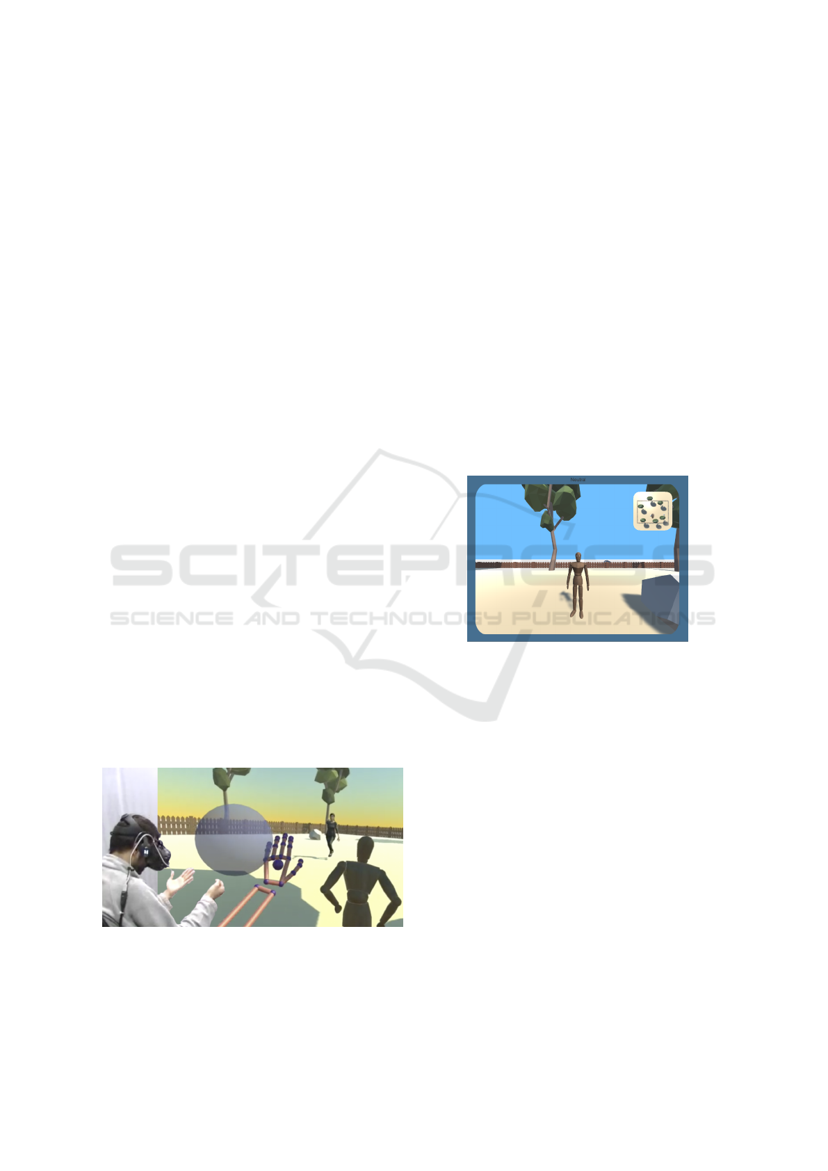
6.1 Visualization for Performers
The first type of user is the performer. He or she will
use the program with the Leap Motion to directly ma-
nipulate the puppet. The Leap Motion is attached to
the user’s forehead, using its Head Mounted mode.
In this way, the visualization can be made either on a
monitor, or with a Head Mounted Device, using vir-
tual or augmented reality. Figure 8 shows the per-
former controlling the puppet in VR mode. In this
case, the puppeteer is litteraly immersed in the scene
and visualizes the puppet in a 3rd person mode.
Figure 8: Third person visualization in VR mode.
An UI element has been added to the performer’s
screen because it was not obvious what manipulation
mode the puppet was in at any given time. In order
to give this information to the performer without dis-
tracting him from the puppet, a “bezel” was chosen.
This bezel has the color associated with the current
mode, and a text field where the mode’s name is dis-
played – in VR mode, the color of the hands are also
changed accordingly (See Figure 9.)
Concerning visualization during runtime, manipu-
lation modes also need different camera setups. Head
and arm manipulation mode’s cameras needs to be
up close and always facing the puppet. On the other
hand, move and jump’s need to stay a bit far away
and to avoid excessive rotation, in order to prevent
disorienting the performer and helping him navigate
the scenario.
In addition to this, a small map of the scenario
has been added to one corner of the screen (most
commonly referred to as a minimap). It shows the
puppet’s current location and the direction it is fac-
ing. This element helps the performer know exactly
in what part of the scenario the puppet is, and its ori-
entation. (See Figure 9.)
Figure 9: Small map used for orientation is shown on the
top-left corner of the screen.
6.2 Visualization for the Audience
Of course, the audience will need a completely dif-
ferent kind of visualization than the performer. Three
types of visualization have been set up for them:
• Big screen:
The most traditional type of visualization, where
the scene is rendered to a single screen. Since
there are many cameras to render from, we have
implemented two ways to choose the correct cam-
era. The first one is automatic: each move-
ment mode has a camera associated with it, and
switching to a different movement mode always
switches to its associated camera. The second one
is manual, and requires the presence of a direc-
tor actively switching between cameras as a scene
unfolds (see below).
• Virtual Reality:
In virtual reality, the audience can navigate in the
GRAPP 2020 - 15th International Conference on Computer Graphics Theory and Applications
68

environment and choose the elements they will
focus on and interact with. This mode uses the
HTC Vive Head Mounted Device, and its SDK
for Unity. It allows performances in a small scale
because of both the high price of the Vive headset
and the bandwidth used by each instance of the
program.
• Augmented Reality:
It is also possible for someone to see the perfor-
mance in AR, by using the Meta II headset. How-
ever, it is not straightforward to make the puppet
interact with the environment and the spectator in
Meta’s SDK . Without these elements, we felt that
augmented reality didn’t contribute to the experi-
ence, so it currently isn’t the focus of the program.
As mentioned above, visualization for the audi-
ence also brings along another kind of user: the direc-
tor. This person will be responsible for choosing what
camera will be recorded or shown in the main screen
and modifying their parameters. To make that pos-
sible, Unity’s Cinemachine system was used to im-
plement and manage different cameras. This mode of
control was inspired in the work of Velho, et al. (Velho
et al., 2018a).
The cameras available represent classic cameras
angles, such as close up shot, full body shot or over
the shoulder. Then, each camera is bound to a key
on the keypad to make switching easier. Zoom-in and
zoom-out are also possible with three distinct speeds.
6.3 Possible Interactions
Since in the Holojam framework every user is aware
of each other, it allows for interactions between per-
formers and with the audience. A performer could for
example notice a spectator looking at an object in the
scenario and react accordingly. It is also possible to
have puppets and fully motion-captured actors shar-
ing the same environment, as in (Velho et al., 2018b).
The puppet can also interact with the scenario
since it is aware of its surroundings. The inverse is
also possible: by adding triggers and colliders, we can
execute behaviors whenever the puppet enters or leave
an area or does a specific movement next to an object.
7 THE FRAMEWORK IN ACTION
As seen in Section 2, development in this field is
closely tied to entertainment, professionals of the
show business and artists. With that in mind, a collab-
oration with a professional puppeteer and a play di-
rector was made. The goal of this collaboration was to
evaluate how the framework would satisfy the needs
of the project, and to improve it.
The objective of the collaboration was to make a
short performance with the puppet, to test its expres-
siveness, and the usability of the program. The name
of this performance is “O Boneco” (The Puppet).
7.1 Development Methodology
Once the project had started, an Agile development
method was set up. There were weekly meetings
where a performer and a director would meet the de-
veloper. Centered around that meeting, our iterative
work-flow functions in the following way:
1. Meeting with users:
The users test the new iteration of the program.
They first see every new change, and then try to
make a short performance using the program.
They give feedback on the improvements made,
and on their experience as a whole. From this
feedback, a list of development tasks is elabo-
rated, where each task has an associated difficulty,
risk, priority and estimated completion time.
2. Improvement:
During the rest of the week, the tasks are then im-
plemented. In general, tasks are done in order of
priority, regardless of difficulty.
Once all the weekly tasks are done, implementa-
tion of backlog features begins. The backlog usu-
ally contains tasks that are more oriented towards
medium and long-term goals in the road-map.
7.2 Learning Process
As in most cases, direct user feedback proved to be
invaluable to improve the program. It is very hard for
a developer to think like a performer, or for a person
who uses this program daily to imagine how someone
using it for the first time will behave.
This feedback made us implement many impor-
tant features, like the bezel around the screen and the
small map mentioned in Section 6.1.
7.3 Results
This collaboration was very fruitful, each week the
recorded performances made significant improve-
ments. The performer managed to adapt very quickly
to the way the program works, and the puppet’s ex-
pressiveness also showed a clear progression in con-
sequence.
Now that our framework has proven itself and is
reaching a mature state, we are already engaged in a
Expanded Virtual Puppeteering
69

complete project that is exploiting all the capabilities
we have created in order to further develop it as an
artistic tool.
8 CONCLUSIONS AND FUTURE
WORKS
We proposed a novel framework for digital puppeteer-
ing that uses a performer’s bare hands. We explained
how it is structured, the modules needed to reproduce
it and the rationale behind the decisions taken dur-
ing the development. The results obtained in Section
7 were very satisfactory, and confirm that the frame-
work allows stable and reliable manipulation of the
puppet while also allowing it to be very expressive.
As for future developments, there are many paths
this framework could follow:
• By using Unity packages such as FinalIK and
PuppetMaster, it is possible to use physics to
make the puppet react to his surroundings in more
complex ways, and enhance existing manipulation
modes. This would further increase the range of
possible interactions between a puppet and its en-
vironment.
• While it is theoretically feasible with the Holo-
jam platform with multiple players, there needs
to be more serious testing of performances featur-
ing many performers simultaneously. Either many
performers, each controlling a different puppet,
a mix of motion captured actors and puppets, or
even many performers controlling a single puppet
(as is the case for more complex puppets in tradi-
tional performances, similar to Boyle’s and Fos-
ter’s work(Boyle and Foster, 2011)).
• Making the creation of new movement modes a
more streamlined process would greatly decrease
the need for direct intervention in the code.
ACKNOWLEDGMENTS
Support by grants from INCTMat and FAPERJ.
REFERENCES
Anderegg, R., Ciccone, L., and Sumner, R. W. (2018). Pup-
petphone: Puppeteering virtual characters using as-
martphone.
Aristidou, A., Lasenby, J., Chrysanthou, Y., and Shamir,
A. (2018). Inverse kinematics techniques in com-
puter graphics: A survey. Computer Graphics Forum,
37:35–58.
Botond G
´
abor, B., G
´
asp
´
ar, H., Kriszti
´
an, K., Tam
´
as, L.,
Tam
´
as, M., G
´
abor, P., Zolt
´
an, C.-K., and D
´
aniel, B.
(2014). Marionette zoo.
Bousquet, M. (2015). Physics for animators.
Boyle, C. and Foster, A. (2011). We be monsters.
Ciccone, L., Guay, M., Nitti, M., and Sumner, R. W. (2017).
Authoring motion cycles. In Proceedings of the ACM
SIGGRAPH / Eurographics Symposium on Computer
Animation, SCA ’17, pages 8:1–8:9, New York, NY,
USA. ACM.
Giulio, M., Fabio, D., and Pietro, Z. (2014). Hand gesture
recognition with leap motion and kinect devices.
Hunter, S. and Maes, P. (2013). Designing digital puppetry
systems: Guidelines and best practices. In CHI ’13
Extended Abstracts on Human Factors in Computing
Systems, CHI EA ’13, pages 2821–2822, New York,
NY, USA. ACM.
Leite, L. and Orvalho, V. (2017). Mani-pull-action: Hand-
based digital puppetry. Proc. ACM Hum.-Comput. In-
teract., 1(EICS):2:1–2:16.
Oshita, M., Senju, Y., and Morishige, S. (2013). Charac-
ter motion control interface with hand manipulation-
inspired by puppet mechanism.
Shiratori, T. and Hodgins, J. K. (2008). Accelerometer-
based user interfaces for the control of a phys-
ically simulated character. ACM Trans. Graph.,
27(5):123:1–123:9.
Souza, A. L. e. L., Marroquim, R., and Velho, L. (2015).
Sketches on natural interactions with virtual scenes.
Souza, C., Kirillov, A., Catalano, M. D., and contributors,
A. (2014). The accord.net framework.
Velho, L., Carvalho, L., and Lucio, D. (2017). In-situ vir-
tual reality. Technical Report TR-03-2017, VISGRAF
Laboratory - IMPA.
Velho, L., Carvalho, L., and Lucio, D. (2018a). Live prob-
abilistic editing for virtual cinematography. In En-
tertainment Computing, number 11112 in LNCS pro-
ceedings. Springer Verlag.
Velho, L., Carvalho, L., and Lucio, D. (2018b). Vr
kino+theater: from the ancient greeks into the future
of media. In Proceedings of ACM SIGGRAPH / Euro-
graphics Symposium on Computer Animation.
Youchen, D., Shenglan, L., Lin, F., Menghui, C., and Jie, W.
(2017). Hand gesture recognition with leap motion.
GRAPP 2020 - 15th International Conference on Computer Graphics Theory and Applications
70
