
Towards Model Transformation from a CBM Model to CEP Rules to
Support Predictive Maintenance
Alexandre Sarazin
1,2
, S
´
ebastien Truptil
1
, Aur
´
elie Montarnal
1
, Jacques Lamothe
1
, Julien Commanay
2
and Laurent Sagaspe
2
1
Industrial Engineering Center, IMT Mines Albi, Albi, France
2
Digital & Software Department, APSYS, Blagnac, France
{sebastien.truptil, aurelie.montarnal, jacques.lamothe}@mines-albi.fr
Keywords:
Maintenance, Knowledge Base, Model Transformation.
Abstract:
Over the past decades, the development of predictive maintenance strategies, like Prognostics and Health
Management (PHM), have brought new opportunities to the maintenance domain. However, implementing
such systems addresses several challenges. First, all information related to the system description and failure
definition must be collected and processed. In this regard, using an expert system (ES) seems interesting.
The second challenge, when monitoring complex systems, is to deal with the high volume and velocity of the
input data. To reduce them, Complex Event Processing (CEP) can be used to identify relevant events, based
on predefined rules. These rules can be extracted from the ES knowledge base using model transformation.
This process consists in transforming some concepts from a source to a target model using transformation
rules. In this paper, we propose to transform a part of the knowledge from a condition-based maintenance
(CBM) model into CEP rules. After further explaining the motivations behind this work and defining the
principles behind model-driven architecture and model transformation, the transformation from a CBM model
to a “generic rules” model will be proposed. This model will then be transformed into an Event Processing
Language (EPL) model. Examples will be given as illustrations for each transformation.
1 INTRODUCTION
According to european stantards (AFNOR, 2018),
maintenance is defined as the “combination of all
technical, administrative and managerial actions dur-
ing the life cycle of an item intended to retain it in,
or restore it to, a state in which it can perform the re-
quired function”. When a maintenance action is car-
ried out in order to assess and/or to mitigate the degra-
dation and reduce the probability of failure of an item,
the maintenance is said preventive. Condition-based
maintenance (CBM) is hence defined as a specific
kind of preventive maintenance including the assess-
ment of the systems physical conditions, their analy-
sis and the determination of possible ensuing mainte-
nance actions.
Condition-based maintenance has become a very
dynamic research topic these past few years, moti-
vated by the constant increase in the systems com-
plexity, the higher quality and safety requirements
and, consequently, the augmentation of time-based
preventive maintenance actions cost (Jardine et al.,
2006). In particular, the concept of PHM has emerged
as “a method that permits the reliability of a system to
be evaluated in its actual life-cycle conditions, to de-
termine the advent of failure, and mitigate the system
risks” (Vichare and Pecht, 2006). It is based on the
observation of the systems sensor data in order to pro-
vide a complete, real-time vision of the systems health
to anticipate potential degradations. The early warn-
ing signs detected from the sensor data allow to per-
forming failure detection and estimate the Remain-
ing Useful Life (RUL) of the system as the degrada-
tion duration before a failure occurs (Blanchard et al.,
1995; Lee et al., 2014).
A PHM approach is comprised of seven main
steps (Lebold et al., 2003) :
1. Sensor-based data acquisition
2. Data preprocessing
3. Condition assessment / Anomaly detection
4. Failure identification / Diagnostic
5. Prognostics / Remaining useful life (RUL) estima-
Sarazin, A., Truptil, S., Montarnal, A., Lamothe, J., Commanay, J. and Sagaspe, L.
Towards Model Transformation from a CBM Model to CEP Rules to Support Predictive Maintenance.
DOI: 10.5220/0008880302050215
In Proceedings of the 8th International Conference on Model-Driven Engineering and Software Development (MODELSWARD 2020), pages 205-215
ISBN: 978-989-758-400-8; ISSN: 2184-4348
Copyright
c
2022 by SCITEPRESS – Science and Technology Publications, Lda. All rights reserved
205
tion
6. Decision support
7. Human-Machine Interface
The data acquisition step is dedicated to the monitor-
ing of the system in its actual life cycle conditions.
Before further analysis, a first processing has to be
performed in order to improve data quality through
cleaning or transform the raw data into more relevant
variables. Once the data have been preprocessed, the
health of the system has to be assessed by anomaly
detection. The detected anomalies are then analysed
in order to identify the root cause and failure. This
step is called diagnostic. If the anomalies detected are
related to the future occurrence of a failure, the RUL
of the system can be evaluated during the prognostics
phase. The results of these analysis are then transmit-
ted to a decision support system and communicated
to the end user through a human-machine interface.
2 OVERVIEW OF THE
PROPOSED PHM APPROACH
Among the numerous solutions proposed to imple-
ment a PHM approach (Jardine et al., 2006; Lee et al.,
2014; DePold and Gass, 1999; Gertler, 1998; Vacht-
sevanos et al., 2006; Lee et al., 2017), a possible solu-
tion is to use an expert system (ES). An ES is a com-
puter program in which expert knowledge is imple-
mented for a specific topic in order to solve problems
or provide some advice (Jackson, 1998). The purpose
of these systems is to mimic the experts reasoning
by performing an analysis based on facts to deliver
a conclusion (Levine and Pomerol, 1990). This ap-
proach is hence based on the formalization of human
knowledge and the mechanisms allowing to perform
its exploitation. For maintenance applications where
experts knowledge is often available and always valu-
able, there is great value in incorporating the capi-
talisation of this experience in maintenance solutions
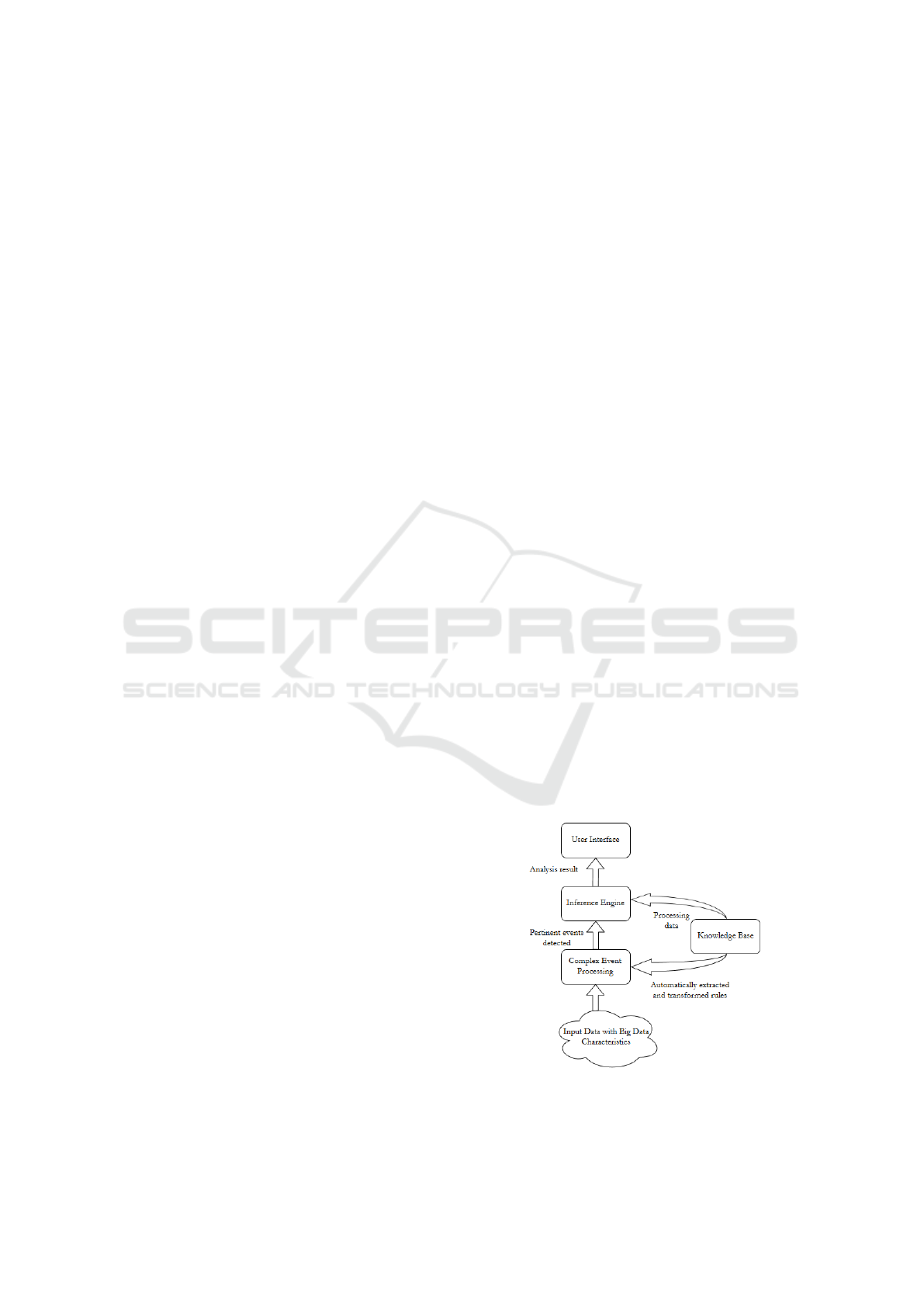
like PHM. ES are composed of three main compo-
nents : a user interface, an inference engine and a
knowledge base (Liebowitz, 1995). The user inter-
face allows the user to interact with the expert system.
The knowledge base is a set of facts and rules related
to the domain. This component may be composed
of a static and dynamic database (Kalogirou, 2003).
The static database contains the domain knowledge
implemented by the human expert which is stable al-
though new facts and rules may be added or modi-
fied. The main interest of using an ES lies in the con-
tent of this database, as such, its must be complete,
consistent and accurate. The dynamic one, however,
changes on a higher frequency as it is used to “store
all information obtained from the user, as well as in-
termediate conclusions (facts) that are inferred during
the reasoning” (Kalogirou, 2003). Its content is lost
at the end of each execution. This knowledge base is
processed by an inference engine in order to reach a
conclusion. It serves as a “control structure [...] that
allows the expert to use search strategies to test differ-
ent hypotheses to arrive at expert system conclusions”
(Liebowitz, 1995). Using an ES can thus be consid-
ered a solution to capitalize and exploit the available
knowledge on the system. In the maintenance con-
text, the rules for anomaly detection, diagnostic and
prognostic must be applied to the input data in order
to identify failures and estimate the RUL.
However, managing the input data is one of the
challenges in implementing CBM, especially to com-
plex systems. Complex systems, like aircrafts, require
many different sensors to perform an acceptable mon-
itoring. The volume and velocity of these inputs are
characteristics of big data problems defined through
the 5V (Jin et al., 2015) : volume of the collected
data, velocity of its update, veracity of the informa-
tion, variety of the sources and value of the informa-
tion. In order to reduce the volume and velocity of
the input data and processe them, a solution is to use
Complex Event Processing (CEP). CEP are designed
to monitor large amounts of data in real time and de-
tect patterns based on predefined rules. This solution
is relevant in reducing the flow of data to allow further
analysis such as diagnostics or prognostics. The main
requirement of this solution is the ability to provide
observation rules as configuration. These observation
rules being present in the ES knowledge base, a criti-
cal step is to automatically extract and transform them
in an Event Processing Language (EPL) to make it us-
able by the CEP (Fig. 1).
Figure 1: Relation between CEP and Expert System.
To adress this problem, this paper proposes a model
MODELSWARD 2020 - 8th International Conference on Model-Driven Engineering and Software Development
206

transformation from a CBM model to CEP rules.
This transformation will be performed in two steps
: The first step is to transform the CBM model into
“generic rules” and from “generic rules” to CEP rules.
The contribution here lies in the definition of the
“generic rules” using a metamodel and the description
of the transformation rules between the three mod-
els. This methodology has been conducted in accor-
dance with the principles of Model-Driven Architec-
ture (MDA)(Belaunde et al., 2003).
3 MODEL-DRIVEN
ARCHITECTURE AND MODEL
TRANSFORMATION
A model is defined as a “formal specification of the
function, structure and/or behavior of an application
or system” (Belaunde et al., 2003). A critical aspect
of a model is the point of view chosen to represent
it. Indeed, a single system can be represented by a
multitude of different models as long as the point of
view changes (Bezivin and Briot, 2004). A model is
most of the time created in accordance with a meta-
model, which is an “explicit specification of an ab-
straction” (Bezivin and Gerbe, 2001) or a “model of
models” (Belaunde et al., 2003). It is used to define
the concepts manipulated in a model and the relations
between them. A model can thus be considered as an
instance of a metamodel.
The main motivation behind the Model Driven
Architecture (MDA) approach is to differentiate the
business concepts manipulated from the technolog-
ical platform used to implement them. In software
development, this allows to differentiate the steps of
design from the business logic to the technical imple-
mentation. According to MDA guide, this method-
ology improves the “portability, interoperability and
reusability” of the end result. The MDA methodol-
ogy is centred around four main categories of models
(Belaunde et al., 2003) :
• The Computation Independant Model (CIM)
• The Platform Independent Model (PIM)
• The Platform Model (PM)
• The Platform Specific Model (PSM)
The CIM is the model designed by a domain expert
with its own vocabulary and without any kind of im-
plementation solution. The PIM includes a first level
of specification making it suitable for different plat-
forms of the same kind. The PM describes the plat-
form used to implement the model. It describes all the
different parts of the platform and the services related
to it. Finally, the PSM is defined as a “view of a sys-
tem from the platform specific viewpoint”. It is the
step beyond the PIM that includes some specificities
of a particular platform (Belaunde et al., 2003).
MDA methodology consists of passing from CIM
to PIM and from PIM to PSM. The process of con-
verting a model into another of the same system is
called model transformation (Belaunde et al., 2003).
A model transformation can also be defined as “a
transformation operation Mt taking a model Ma as
the source model and producing a model Mb as the
target model”. All models must conform to their own
metamodels, conforming themselves to a metameta-
model (Bezivin et al., 2006). In a model transforma-
tion approach, all concepts are not commonly shared
by the source and target models. In fact, the first
step of a model transformation is to identify, in each
model, the shared concepts, where lies the domain of
the transformation, and the specific concepts, which
are not shared (Fig. 2). The shared concepts are then
transformed from the source to the target model using
transformation rules (mapping rules). In the source
model, the specific part can thus be assimilated to cap-
italized knowledge while the specific concepts of the
target model correspond to additional knowledge that
has to be implemented from external sources(Truptil
et al., 2010).
Figure 2: “Model transformation principle” (Truptil et al.,
2010).
In this paper, the CBM model and the “generic rules”
model can be assimilated to CIMs, while the model
for the CEP rules refers to a PIM as EPL is a com-
mun to different CEP languages such as EQL, CQL,
SteamSQL or CCL. The point of this paper is to de-
fine the “generic rules” CIM and explicit the trans-
formation rules between the two CIMs and from the
“generic rules” to the PSM (Fig 3).
Towards Model Transformation from a CBM Model to CEP Rules to Support Predictive Maintenance
207

Figure 3: Model transformation from a CBM to EPL rules.
4 FROM A CBM MODEL TO
GENERIC RULES
4.1 Presentation of the CBM
Metamodel
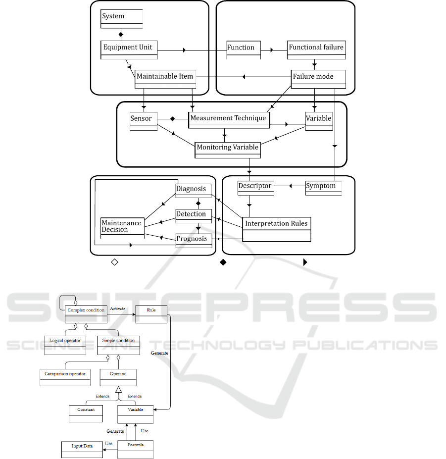
The metamodel chosen to define the CIM has been
designed by Guill
`
en et al. (Guillen et al., 2016). This
metamodel describes the different parts of a CBM so-
lution with concepts defined from ISO standards (Fig.
4). In this metamodel, a CBM solution is divided into
5 parts:
• Physical Description
• Functional Description
• Information Sources
• Symptom Analysis
• Maintenance Decision-Making
The “Physical Description” part regroups all infor-
mation related to the systems composition. It de-
scribes the different components to the maintainable
items level which are “the group of parts of the
equipment unit that are commonly maintained (re-
paired/restored) as a whole” (ISO, 2017).
The “Functional Description” part lists the func-
tions assured by the equipment units. For each func-
tion, the functional failures associated are also de-
scribed and the failure modes for each functional fail-
ure are provided.
The “Information Sources” block describes the
elements related to information gathering such as
sensor data, variables, and measurement techniques.
These elements are used to generate monitoring vari-
ables designed as basis for analysis.
The forth part is the ”Symptom Analysis” block
which defines the descriptors, symptoms and infor-
mation rules. A descriptor is a “feature, data item
derived from raw or processed parameters or external
observation” (ISO, 2012). They are obtained from the
processing of one or several monitoring variables. A
symptom is a “perception, made by means of human
observations and measurements (descriptors), which
may indicate the presence of one or more faults with
a certain probability” (ISO, 2012). Finally, an inter-
pretation rule is “the description of how the descriptor
values have to be interpreted or treated in order to get
the monitoring outputs (detection, diagnosis, progno-
sis) for a failure mode” (Guillen et al., 2016).
The last part, the “Maintenance Decision-
Making” block, supports the anomaly detection, di-
agnosis and prognosis activities. These actions are
triggered by the activation of the interpretation rules
and provide a list of potential maintenance decisions.
The detection element is designed to analyse the state
of the system and detect abnormal behaviours. Its pur-
pose is to confirm the occurrence of a failure and re-
duce the rate of false positives. The diagnosis element
refers to the failure identification activity. It is defined
as a “conclusion or group of conclusions drawn about
a system or unit under test” (ISO, 2012). Its purpose
is to identify the deficient component and the source
and/or nature of the failure. The prognosis is the “es-
timation of time to failure and risk for one or more
incipient failure modes” (ISO, 2012). Its purpose is
to estimate the remaining duration before a failure oc-
curs also called Remaining Useful Life (RUL) and an-
ticipate the emergence of new risks.
The relevance of this model comes from the ex-
haustiveness of the concepts, all based on standards,
and the relations between these concepts required to
perform CBM.
4.2 Presentation of the “Generic Rules”
Metamodel
As illustrated in Fig.3 the target model of the
first model transformation describes the structure of
generic rules. This model serves as a medium be-
tween the CBM model and the EPL model. There
are three purposes behind this model.
First, it reduces the scope of the CBM to observa-
tion rules only, discarding any maintenance specific
concept. This way, the model allows generic rules to
be defined for a larger scope of models and may not
be restricted to maintenance only. As it is indepen-
dent from the source model, it is also resilient to any
modification of the CBM model and only the transfor-
mation rules would be affected by such modifications.
The second purpose is related to the second trans-
formation. As the generic rules are not event-oriented,
they are also independent from the EPL model, im-
proving the architectures flexibility by allowing no-
EPL rule-based solutions to be more easily imple-
mented.
The third purpose for designing this model for
generic rules is to allow 1-to-n transformations for the
second transformation, meaning that a single generic
MODELSWARD 2020 - 8th International Conference on Model-Driven Engineering and Software Development
208
Block 1
Physical
Description
Block 2
Functional
Description
Block 3
Information
Sources
Block 5
Maintenance
Decison-Making
Block 4
Symptom
Analysis
Executes
It has
May have
May have
Related to
May have
It has
May have
May have
May generate
May have
May generate
Generate
Generate
Related
Generate
It has
It has
May
generate
May
generate
May
generate
May
generate
May
generate
May
generate
Generate
Generate
Generate
Aggregation as binary association
Composite aggregation
Association
Figure 4: “Basic structure for the CBM solution presented in an UML diagram” (Guillen et al., 2016).
Figure 5: Generic Rules Model.
rule can generate several EPL rules.
In this model (Fig. 5), a generic rule is assimi-
lated to a complex condition. This complex condi-
tion can be generated by aggregation of other condi-
tions, either complex or simple, with logical opera-
tors (for instance and, or, not). A simple condition,
which is the elementary form of condition, is com-
posed of operands linked by a comparison operator
(equal, greater than etc...). An operand can be a con-
stant or a variable generated from input data process-
ing. The processing is described here as the genera-
tion of a variable by a formula using input data and/or
other variables as input. When all conditions are ful-
filled, the rule generates one or several output vari-
ables.
4.3 Transformation Rules and
Illustration
Once the source and target models and defined, the
model transformation can begin. As previously men-
tioned, the first step is to identify the concepts shared
by both models. In the source model, the relevant el-
ements for a rule definition are:
• the monitoring variable which can be considered
as inputs
• the descriptors which define how the monitoring
data should be processed
• the symptoms for rule characterization
• the interpretation rules to define the activation
conditions including operators and threshold val-
ues
• the detection, diagnosis and prognosis elements to
indicate which actions should be triggered by the
rule activation
In order to connect these elements to concepts of the
target model, transformation rules have been gener-
ated and summed up in Table 1. According to this
Towards Model Transformation from a CBM Model to CEP Rules to Support Predictive Maintenance
209
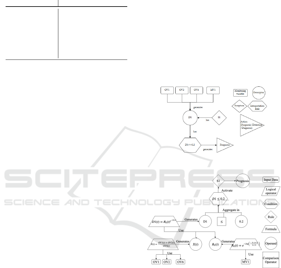
Table 1: Transformation Rules from a CBM Model into
Generic Rules.
CBM Model Concept Generic Rule Model Concept
Monitoring Variable Input Data
Descriptor Variable
Descriptor Formula
Symptoms Rule
Interpretation Rule Complex Condition
Detection Variable
Diagnosis Variable
Prognosis Variable
mapping, the monitoring variables correspond to the
input data as they refer to elemental signals or infor-
mation. The descriptors are related to two of the tar-
gets concepts. In the source model, this component is
a “data item derived from raw or processed parame-
ters”. In order to define it, intermediate variables must
be generated using functions. It is therefore related to
the Formula and Variable Operand elements of the tar-
get model. The Symptom component provides busi-
ness logic on the state of the system depending on
the activation of the conditions activation. It can thus
be mapped to the target models Rule. The Interpre-
tation Rules function is to compare the descriptors to
threshold values. As such it is composed of Compar-
ison Operators and Constant Operands. The Detec-
tion, Diagnosis and Prognosis elements are the rules
output. In the source model, they refer to the actions
performed once the conditions of the Interpretation
Rule are fulfilled. In the target model, they are assim-
ilated as Variables indicating the nature of the actions
to perform. In the global architecture, these actions
should then be performed by the expert systems infer-
ence engine.
Two illustrations of this transformation are pro-
posed based on the use case of an industrial power
transformer. These examples have been defined by
Guill
`
en et al. in order to illustrate the CBM model.
They will here be transformed into generic rules and
into EPL rules in the next chapter in order to illus-
trate the second model transformation. Following this
approach, these examples will be processed by both
model transformations, turning the elements of the
knowledge base into EPL rules. For both examples,
the shared concepts and related failure modes are de-
scribed in Table 2.
The first example describes the detection of the
failure mode “lack of outflow” of the maintainable
item “Refrigeration”. The symptom to be detected
is an abnormal correlation between the oil tempera-
ture and the current output of the power transformer.
In order to detect this symptom, the monitored vari-
ables are the upper and lower oil layer temperature,
the load current in output and the number of mainte-
nance interventions. These monitoring variables are
then processed using a reliability function to generate
a descriptor. When the descriptor, alias the value the
reliability function, becomes inferior to 20%, a prog-
nosis action is then triggered. A model of this exam-
ple according to the source model is represented in
Fig 6. Applying the above mentioned transformation
rules to this model, the corresponding target model
has been designed in Fig 7. The particularity of this
example is the aggregation a several monitoring data
into a single descriptor using complex formulas. As
a reminder, these formulas are hidden inside the De-
scriptor element of the source model.
Figure 6: First Example of a CBM model adapted from
(Guillen et al., 2016).
Figure 7: First Example of a Generic Rule Model.
The second example concerns the detection of the
failure mode “short-circuit” of the power transform-
ers core. the symptom observed is the combination
of an anomaly between the over-current and service
current and the presence of hydrogen and CO gener-
ated by the short-circuit. The monitored variables are
the quantity of hydrogen compared to normal service
values (OV5), the load current(OV6) and the quantity
of CO (OV8). The particularity of this example is that
each monitoring variable is a descriptor. The interpre-
tation rule states that OV5 must be above 50% and the
load current and CO level must be positive in order to
activate the rule and perform detection and diagnosis
MODELSWARD 2020 - 8th International Conference on Model-Driven Engineering and Software Development
210
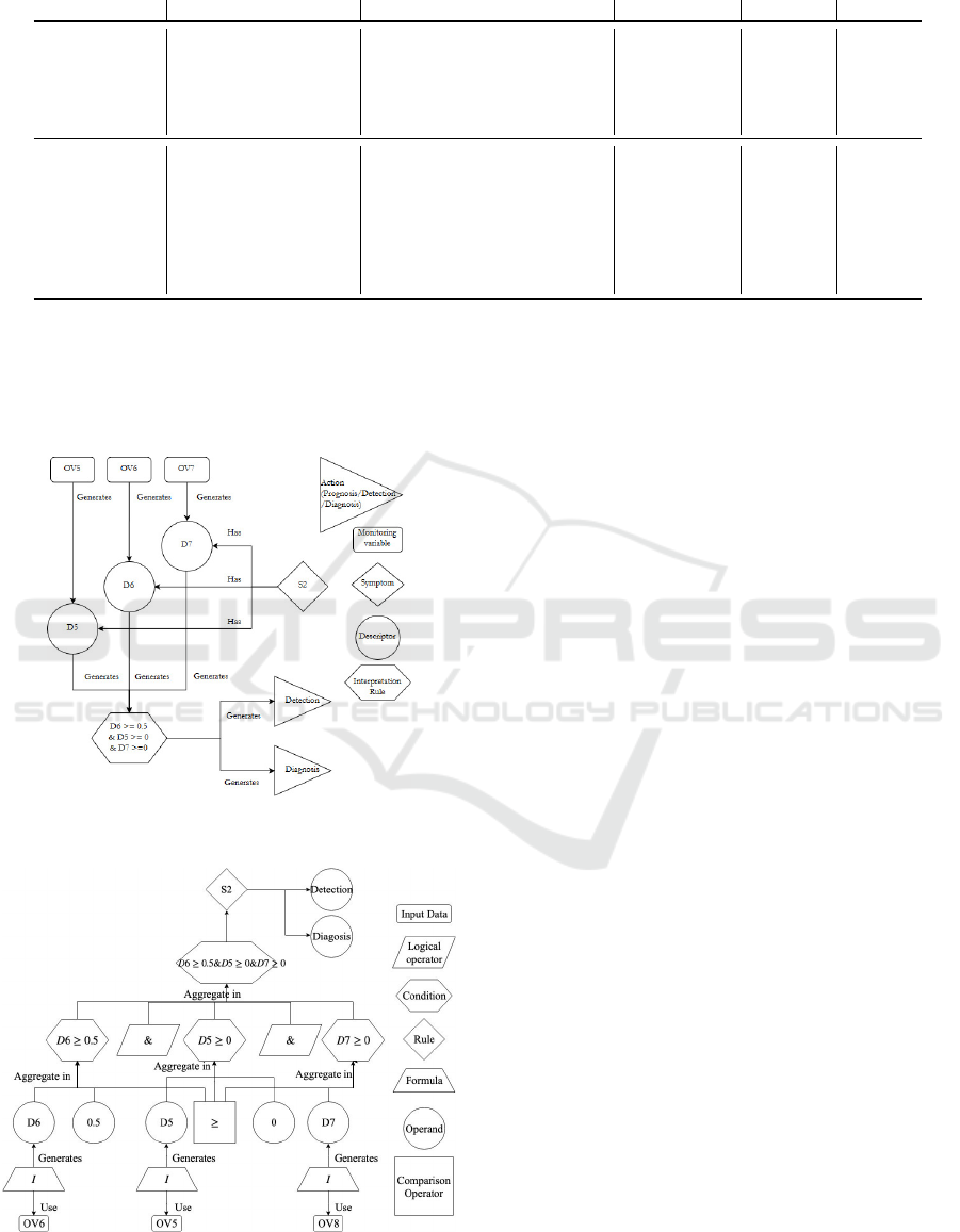
Table 2: Presentation of the Shared Concepts for two Examples of Failure Modes adapted from (Guillen et al., 2016).
Failure Mode Symptom Monitoring Variable Decriptor Action IR
Lack of outflow S1 - Relation of the oil OV1 - Upper oil layer temp. (
◦
C) D1 = R(t,OV1, Prognosis D1≤0.2
temperature and the OV2 - Lower oil layer temp. (
◦
C) OV2, OV6,
current output in the OV6 - Load current (A) MV1)
power transformer MV1 - Number of maintenance
interventions
Short circuit S2 - Over-current OV5 - Hydrogen level (%) D5 = OV5 Detection, D6 ≥0.5
considerably higher than Diagnosis &
service current, OV6 - Load current(A) D6 = OV6 D5 ≥ 0
confirmed also by the &
presence of hydrogen OV8 - CO level (%) D7 = OV7 D7 ≥ 0
and CO as a result of
the arc
activities. The instantiation of the source model with
this example is represented in Fig. 8. Its transforma-
tion into a generic rule, according to the transforma-
tion rules in Table 1, is described in Fig. 9.
Figure 8: Second Example of a CBM Model adapted from
(Guillen et al., 2016).
Figure 9: Second Example of a Generic Rule Model.
These examples illustrate how the mapping rules pre-
sented in Table 1 can be used to perform the trans-
formation process from an expert system knowledge
base, defined here using the CBM model of Guill
`
en et
al. , into generic rules.
5 FROM GENERIC RULES TO AN
EPL MODEL
5.1 Presentation of the EPL Metamodel
Once the generic rules are defined, they have to be
transformed to comply with Event Processing Lan-
guages (EPL). EPLs are SQL-like languages designed
support CEP solutions by defining events, conditions
and patterns in order to detect interesting behaviors in
the data (Boubeta-Puig et al., 2014). Esper or Siddhi
are some examples of well-known EPL-based solu-
tions.
According to Boubeta-Puig et al. (Boubeta-Puig
et al., 2014), one of the downsides of these systems
is their first hand complexity. In order to ease the
domain experts work in implementing CEP solutions
despite the lack of EPL knowledge, a model for EPL
and an automatic model-to-code solution have been
designed (Boubeta-Puig et al., 2014). This model-to-
code implementation can be assimilated as a PIM to
PSM transformation, the PIM being the EPL model
and the PSM being the generated code. In order to
rely on the above mentioned work, the target model
for the model transformation is the model presented
in Fig.10.
In this model, the EPL is composed of three main
types of components : the “SearchConditions” com-
ponent, the “Pattern” component and the “Output”
component. The “Link” component is designed to
establish the relationships between the elements con-
tained in the three main components.
Towards Model Transformation from a CBM Model to CEP Rules to Support Predictive Maintenance
211
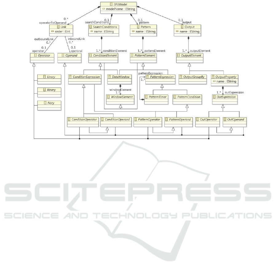
Figure 10: “EPL Metamodel” (Boubeta-Puig et al., 2014).
The “Link” component is divided into operands
and operators. Operators correspond here to the op-
eration being performed on one or several operands.
These operators can either be Unary, Binary or N-ary
depending on the number of operands them can be
applied on.
The “SearchConditions” component regroups the
“ConditionsElements”. These elements are designed
to join event streams or filter events and are composed
of data windows and condition expressions. The data
windows consist of “bounded set of events from an
event stream” while condition expressions define the
type of operation to be performed and the type of
operand they must be performed on. The condition
operators can either be comparison operators (equal,
greater than, etc...), arithmetic operators (addition,
subtraction etc...) or logical (and, not, or).
The “Pattern” component is defined as “a tem-
plate specifying conditions which can match sets of
related events”. It is composed of at least one “Patter-
nElement” which associate a pattern expression with
a DataWindow element. The pattern expression is a
set of particular conditions specific to pattern man-
agement including pattern timers. These components
are not being shared by the generic rules. The im-
plementation of these elements should be performed
using additional knowledge according to Fig. 2.
Finally, the “Output” component specify the fea-
tures of the complex event generated by the rules acti-
vation. It can be composed of several events each pos-
sessing properties and generated using expressions.
Further details about the elements of this model
are available in Boubeta-Puig et al. (Boubeta-Puig
et al., 2014).
5.2 Transformation Rules and
Illustration
As mentioned above, the scope of shared concepts be-
tween the generic rule model and the EPL model does
not include the event patterns as events are not defined
in the source model. The transformation rules from
the generic rule to EPL are described in Table 3.
The concept of Input Data in the source model can
be easily assimilated to Window Elements as they cor-
respond to the lowest level of monitoring data. How-
ever, the concept of generating variables using for-
mulas is less simple. The solution proposed is to cre-
ate an OutputElement for each variable, consequently
considering a formula as an OutExpression. This Ou-
tExpression generates an Output property which is
the value of the variable. These OutputElement can
then be integrated into another EPL rule as a Win-
dowElement. Here lies one of the purposes of using
the generic rule model as it allows 1-to-n transforma-
tions from a single generic rule into several EPL rules.
The complex conditions of the source model are a set
of simple conditions aggregated together using log-
ical operators. This structure is similar to the EPL
concepts of SearchConditions as they are defined as
a set ConditionElements related to each others by op-
erators. However, in opposition with variables which
are assimilated to WindowElements as they are dy-
namically generated, the constant operands are stable
MODELSWARD 2020 - 8th International Conference on Model-Driven Engineering and Software Development
212
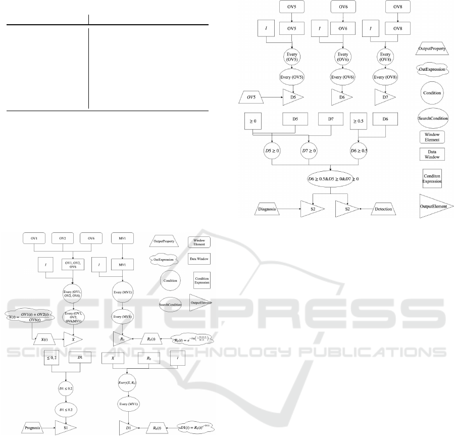
Table 3: Transformation Rules from Generic Rules to EPL.
Generic Rule Model EPL Model
Input Data WindowElement
Formula OutExpression
Variable WindowElement/ OutputElement
Constant ConditionOperand
Simple Condition ConditionElement
Multiple Condition SearchConditions
Comparison Operator Operator
Logical Operator Operator
and should then be considered as a part of the condi-
tion. For this reason, constant operands are mapped
as ConditionOperands.
This mapping is illustrated by the two examples
defined in the previous chapter. Considering the first
example, the result of the transformation from generic
rule (Fig.7) into EPL rules, using the mapping pre-
sented above, is represented in Fig. 11.
Figure 11: First Example of an EPL Model.
In this example, four OutputElements are genrated
by four different EPL rules. The first rule creates
an OutputElement X every time a set of Window-
Elements OV1, OV2 and OV8 is collected. The sec-
ond example creates the OutputElement R
0
from the
number of maintenance activities MV1. These Out-
puElements are then aggregated in a third rule to pro-
duce the descriptor D1 as a third OutputElement. Fi-
nally, a fourth rule check the value of D1 using the
ConditionElement “≤ 0.2” to produce or not an Out-
putEvent S1 with the OutputProperty “Prognosis”,
meaning that the symptom as been detected and in-
dicating that a prognosis action has to be performed.
The result of the transformation for the second ex-
ample is represented in Fig.12.
Figure 12: Second Example of an EPL Model.
In this example four rules are also required as three
descriptors have to be generated before being tested
and protentially producing an OutputElement for the
symptom. The first rule produces the OutputElement
D5 for each WindowElement OV5 received. The
same process is used to create the OutputElement
D6 from the WindowElement OV6 and to create the
OutputElement D7 from the WindowElement OV8.
These OutputElements are then used as WindowsE-
lement for the fourth rule. In this rule, three Con-
ditionElements check a DataWindow each. These
ConditionElements are aggregated in a more com-
plex SearchConditions element and produce two Out-
putElements with detection and diagnosis Output-
Properties.
These examples show how the mapping presented
in Table 3 can be used to produce EPL rules form a
generic rule. A limit of this transformation may be
the large number of event produced considering that
each variable generation requires a rule to be defined
and an event to be created. This limit may affect the
CEP performance also the impact of this influence as
yet to be measured.
6 PERSPECTIVES AND FUTURE
WORK
This paper discusses about the interoperability of Ex-
pert Systems (ES) with Complex Event Processing
(CEP) solutions. In the maintenance domain, the
multiplication of the data sources have boosted the
development of condition-based maintenance strate-
Towards Model Transformation from a CBM Model to CEP Rules to Support Predictive Maintenance
213

gies and given birth to new approaches such as Prog-
nostics and Health Management (PHM). At the same
time, data management has also become a challenge
that can be neglected no more. As we believe that
ES are relevant solutions for implementing PHM so-
lutions due to their ability to capitalize and process
available knowledge on a systems and its failures, we
propose to combine this systems with CEP solutions.
The purpose of using CEP is to filter to flow of input
data in order to detect the relevant events for further
analysis. In order to match these systems we pro-
pose to implement a model transformation approach
to extract knowledge from the ES knowledge base
and transform it into CEP rules. This transformation
is divided in two steps. The first phase consists in
transforming the relevant concepts of the knowledge
base into generic rules. The second phase transforms
these generic rules into CEP rules conforming to the
Event Processing Language. The purpose of defining
generic rules lies in the improved flexibility granted
to the transformation and the possibility to perform 1-
to-n transformations between these generic rules and
EQL rules.
The limit of this approach is the current lack of
computing implementation in a real case, which our
future work will focus on.
REFERENCES
AFNOR (2018). NF EN 13306 - Maintenance — Termi-
nologie de la maintenance.
Belaunde, M., Casanave, C., DSouza, D., Duddy, K.,
El Kaim, W., Kennedy, A., Frank, W., Frankel, D.,
Hauch, R., and Hendryx, S. (2003). MDA Guide Ver-
sion 1.0. 1.
Bezivin, J. and Briot, J.-P. (2004). Sur les principes de base
de l’ing
´
enierie des mod
`
eles. L’OBJET, 10(4):145–
157.
Bezivin, J., B
¨
uttner, F., Gogolla, M., Jouault, F., Kurtev,
I., and Lindow, A. (2006). Model Transformations?
Transformation Models! In Nierstrasz, O., Whittle,
J., Harel, D., and Reggio, G., editors, Model Driven
Engineering Languages and Systems, Lecture Notes
in Computer Science, pages 440–453. Springer Berlin
Heidelberg.
Bezivin, J. and Gerbe, O. (2001). Towards a precise defi-
nition of the OMG/MDA framework. In Proceedings
16th Annual International Conference on Automated
Software Engineering (ASE 2001), pages 273–280.
Blanchard, B. S., Verma, D. C., and Peterson, E. L. (1995).
Maintainability : a key to effective serviceability and
maintenance management. New York : John Wiley &
Sons, Inc.
Boubeta-Puig, J., Ortiz, G., and Medina-Bulo, I. (2014).
A model-driven approach for facilitating user-friendly
design of complex event patterns. Expert Systems with
Applications, 41(2):445–456.
DePold, H. R. and Gass, F. D. (1999). The Application of
Expert Systems and Neural Networks to Gas Turbine
Prognostics and Diagnostics. Journal of Engineering
for Gas Turbines and Power, 121(4):607–612.
Gertler, J. (1998). Fault Detection and Diagnosis in En-
gineering Systems. CRC Press. Google-Books-ID:
fmPyTbbqKFIC.
Guillen, A. J., Crespo, A., G
´
omez, J. F., and Sanz, M. D.
(2016). A framework for effective management of
condition based maintenance programs in the context
of industrial development of E-Maintenance strate-
gies. Computers in Industry, 82:170–185.
ISO (2012). ISO 13372, Surveillance et diagnostic des ma-
chines — Vocabulaire.
ISO (2017). NF EN ISO 14224 - Petroleum, petrochemical
and natural gas industries - Collection and exchange
of reliability and maintenance data for equipment.
Jackson, P. (1998). Introduction to Expert Systems.
Addison-Wesley Longman Publishing Co., Inc.,
Boston, MA, USA, 3rd edition.
Jardine, A. K. S., Lin, D., and Banjevic, D. (2006). A re-
view on machinery diagnostics and prognostics im-
plementing condition-based maintenance. Mechani-
cal Systems and Signal Processing, 20(7):1483–1510.
Jin, X., Wah, B. W., Cheng, X., and Wang, Y. (2015). Sig-
nificance and Challenges of Big Data Research. Big
Data Research, 2(2):59–64.
Kalogirou, S. A. (2003). Artificial intelligence for the
modeling and control of combustion processes: a re-
view. Progress in Energy and Combustion Science,
29(6):515–566.
Lebold, M., Reichard, K., and Boylan, D. (2003). Uti-
lizing dcom in an open system architecture frame-
work for machinery monitoring and diagnostics. In
2003 IEEE Aerospace Conference Proceedings (Cat.
No.03TH8652), volume 3, pages 3 1227–3 1236.
Lee, J., Jin, C., Liu, Z., and Ardakani, H. D. (2017). Intro-
duction to data-driven methodologies for prognostics
and health management. In Probabilistic prognostics
and health management of energy systems, pages 9–
32. Springer.
Lee, J., Wu, F., Zhao, W., Ghaffari, M., Liao, L., and Siegel,
D. (2014). Prognostics and health management design
for rotary machinery systems—Reviews, methodol-
ogy and applications. Mechanical Systems and Signal
Processing, 42(1):314–334.
Levine, P. and Pomerol, J.-C. (1990). Syst
`
emes interactifs
d’aide
`
a la d
´
ecision et syst
`
emes experts. Herm
`
es.
Liebowitz, J. (1995). Expert systems: A short introduction.
Engineering Fracture Mechanics, 50(5):601–607.
Truptil, S., B
´
enaben, F., Salatge, N., Hanachi, C., Cha-
purlat, V., Pignon, J.-P., and Pingaud, H. (2010). Me-
diation Information System Engineering for Interoper-
ability Support in Crisis Management. In Popplewell,
K., Harding, J., Poler, R., and Chalmeta, R., edi-
tors, Enterprise Interoperability IV, pages 187–197.
Springer London.
Vachtsevanos, G., Lewis, F., Roemer, M., Hess, A., and Wu,
B. (2006). Systems Approach to CBM/PHM. In Intel-
MODELSWARD 2020 - 8th International Conference on Model-Driven Engineering and Software Development
214

ligent Fault Diagnosis and Prognosis for Engineering
Systems, pages 13–55. John Wiley & Sons, Inc.
Vichare, N. M. and Pecht, M. G. (2006). Prognostics
and health management of electronics. IEEE Trans-
actions on Components and Packaging Technologies,
29(1):222–229.
Towards Model Transformation from a CBM Model to CEP Rules to Support Predictive Maintenance
215
