
Iterative Color Equalization for Increased
Applicability of Structured Light Reconstruction
Torben Fetzer
1
, Gerd Reis
2
and Didier Stricker
1,2
1
Department of Computer Science, University of Kaiserslautern, Germany
2
Department Augmented Vision, DFKI GmbH, Germany
Keywords:
Structured Light, 3D-Reconstruction, Color Equalization, Photometric Compensation.
Abstract:
The field of 3D reconstruction is one of the most important areas in computer vision. It is not only of the-
oretical importance, but is also increasingly used in practice, be it in reverse engineering, quality control or
robotics. A distinction is made between active and passive methods, depending on whether they are based
on active interactions with the object or not. Due to the accuracy and density of the reconstructions obtained,
the structured light approach, whenever applicable, is often the method of choice for industrial applications.
Nevertheless, it is an active approach which, depending on material properties or coloration, can lead to prob-
lems and fail in certain situations. In this paper, a method based on the standard structured light approach
is presented that significantly reduces the influence of the color of a scanned object. It improves the results
obtained by repeated application in terms of accuracy, robustness and general applicability. Especially in
high-precision reconstruction of small structures or high-contrast colored and specular objects, the technique
shows its greatest potential. The advanced method requires neither pre-calibrated cameras or projectors nor
information about the equipment. It is easy to implement and can be applied to any existing scanning setup.
1 INTRODUCTION
Modern structured light systems typically consist of
a projector that illuminates the scene through several
fringe patterns and at least one camera that captures
the lit scene. There are several techniques based on
binary patterns, pseudo-random patterns, and finally
phase-shifted structured light known as state of the
art. The calculation of phase images for each camera
from the patterns projected ensures continuous sur-
face encoding. This allows dense correspondence to
be determined between all views, including the pro-
jector. Based on the resulting high-quality correspon-
dences, modern auto-calibration techniques ((Zhang,
1998), (Fetzer et al., 2019), (Lourakis and Deriche,
2000), (Hartley and Zisserman, 2003)) ensure that
camera matrices can be estimated robustly, ready for
triangulation of point clouds. In this way, a calibra-
tion of the devices is generated that achieves highest
accuracy on the object’s surface. This in turn leads to
high-precision reconstructions and is a superiority of
this method over other scanning techniques.
This work was funded by the project MARMORBILD
(03VP00293) of the German Federal Ministry of Education
and Research (BMBF).
In addition to the strengths of structured light,
there is a number of disadvantages that should by
no means be neglected. The basis of the process is
the visibility of the projections on the object’s sur-
face. In this context, transparent, mirroring and spec-
ular scenes should be mentioned above all. Even ob-
jects whose texture contains both highly absorbent
and highly reflective areas can cause problems. In
many cases such scenes lead to inaccuracies and often
to a complete failure of the method. With this work
we want to eliminate or at least reduce some of these
problems in a way that can be easily adopted to exist-
ing scan setups. We significantly increase the appli-
cation area of structured light reconstruction without
additional hardware requirements.
According to the state of the art, shifted sinusoidal
fringe patterns are used which sum up to zero. There-
fore, the encoding method should be invariant to the
object’s texturing. The following reflection properties
are unfortunately neglected in this idealized model:
• Different materials cause different light reflection.
• Different colors reflect the light in different ways.
Therefore, in many cases the appearance of the pro-
jected fringe patterns can change into the impercep-
Fetzer, T., Reis, G. and Stricker, D.
Iterative Color Equalization for Increased Applicability of Structured Light Reconstruction.
DOI: 10.5220/0008879607250732
In Proceedings of the 15th International Joint Conference on Computer Vision, Imaging and Computer Graphics Theory and Applications (VISIGRAPP 2020) - Volume 4: VISAPP, pages
725-732
ISBN: 978-989-758-402-2; ISSN: 2184-4321
Copyright
c
2022 by SCITEPRESS – Science and Technology Publications, Lda. All rights reserved
725
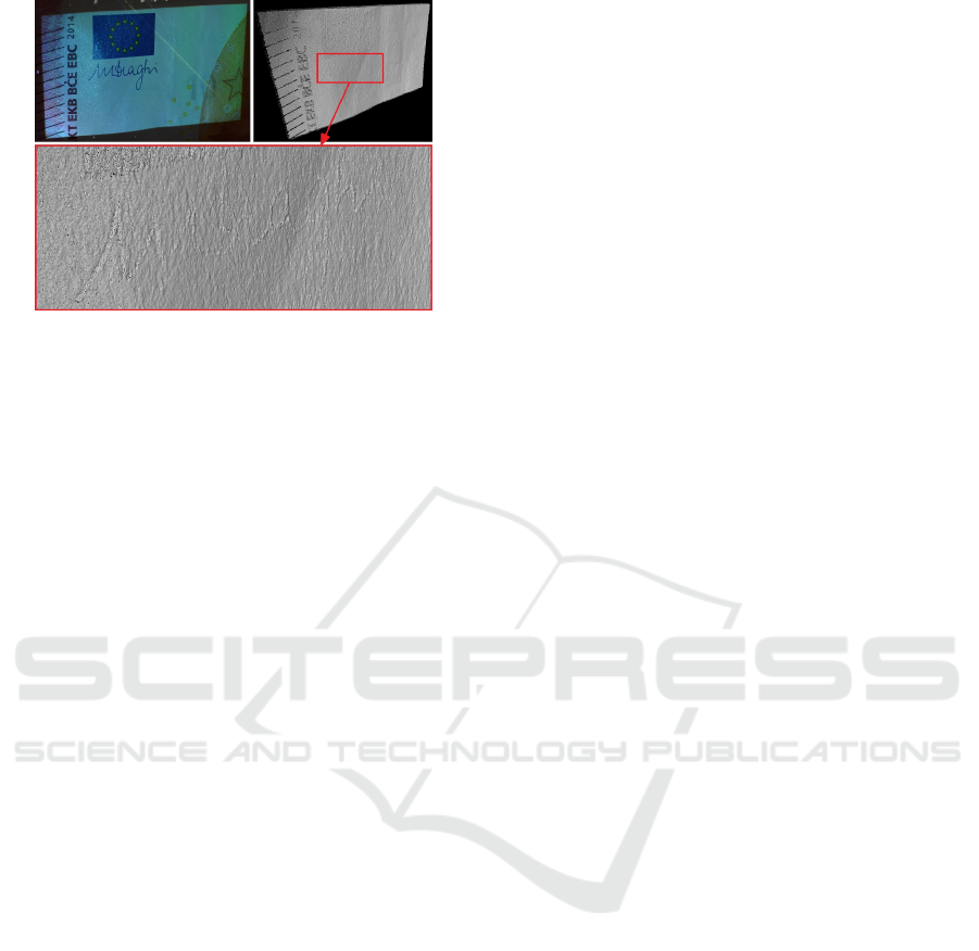
Figure 1: Recorded section of a 10-euro note (top left) and
corresponding point cloud, reconstructed by structured light
(top right). The enlarged area (below) shows errors in the
estimated depth, solely caused by the object’s coloration.
tible. Most reconstructions of objects made of stan-
dard material are not very strongly affected and time-
consuming procedures, to always treat this behavior,
would certainly be overdone. Nevertheless, this ef-
fect is clearly noticeable in high-precision reconstruc-
tions and it is worth taking a closer look. To illustrate
this, Figure 1 shows a captured area of a 10-euro note
and a point cloud thereof reconstructed with struc-
tured light. The enlargement of the point cloud clearly
shows the erroneous depth caused exclusively by the
texturing of the object. The combination of the pro-
jection patterns with an inverse texture significantly
reduces this effect.
2 RELATED WORK
Modern phase-shifted structured light systems with
digital devices were introduced in (Zhang and Huang,
2004). In order to shorten the acquisition time,
(Zhang and Huang, 2006) and before (Zhang et al.,
2002) introduced methods that use color-coded pat-
terns. (Sansoni and Redaelli, 2005) and later (Yang
et al., 2017) introduced single shot structured light
techniques, where the multiple shifted fringe im-
ages were coded by carrier waves and combined to
one pattern. (Donlic et al., 2015) and (Petkovi
´
c
et al., 2016) presented single-shot structured light ap-
proaches, based on de bruijn color sequences. All
methods to shorten the acquisition time reduced the
quality of reconstructions significantly. In (Zhang and
Yau, 2008) a setup with two cameras is presented
to significantly increase the scan quality. When us-
ing several cameras (ideally the same camera model)
there are many advantages with regard to calibration,
gamma correction of the recorded scenes and the re-
sulting quality of the reconstructions. Although, the
approach based on this technique has become state
of the art in many areas, there are several scenarios,
where this approach is not applicable.
Extensive research has been carried out to im-
prove the applicability to general situations. In order
to cope with strong ambient lighting such as sunlight,
(Gupta et al., 2013) introduced a possibility of com-
pensation by sequentially allocating a given energy
budget to several sections. (Nayar et al., 2006) and
later (O’Toole et al., 2014), (O’Toole et al., 2012) pre-
sented ways to split direct and indirect light paths, en-
abling the reconstruction of mirroring, reflecting and
light emitting objects and even scanning through dust.
Unfortunately, this requires expensive hardware, the
process is error-prone and requires high-precision cal-
ibration of camera pixels to a DLP panel, making
it difficult to use for practical applications. (Wein-
mann et al., 2011) increased the range of application
of structured light but using additional devices.
3 INVERSE TEXTURE
First of all, we want to investigate the influence of
a projection to the captured image of a scene. We
then present a procedure that modulates the projec-
tion in such a way that as many points as possible in
the scene have an equivalent influence to the captured
image. This procedure equalizes the appearance of an
object iteratively and converges after only a few steps.
The projector-camera correspondences are generated
using the structured light approach and are reliably
cleaned of erroneous phases with the help of a newly
introduced simple masking method.
Let I be a captured image of a scene that was il-
luminated by a projection T . Schreiber and Bruning
(Malacara, 2007) described the physical influence of
T on image I. Accordingly, the captured image can
be approximated as the composition
I = I
0
+ I
00
◦ T, (1)
of the average intensity I
0
and the scene intensity I
00
,
moduled by the projected texture T . Thereby, ◦ de-
notes the element-wise multiplication operator.
In order to minimize the influence of the coloring
of an object to its image, projection texture T has to be
estimated so that it balances the object colors as much
as possible. Therefore, the following minimization
problem has to be solved:
argmin
T,
¯
I
∑
i j
(I
i j
−
¯
I)
2
= argmin
T,
¯
I
∑
i j
(I
0
i j
+ I
00
i j
T
i j
−
¯
I)
2
(2)
While I
i j
denotes the pixels of image I and
¯
I the op-
timal common color value of the equalized pixels.
VISAPP 2020 - 15th International Conference on Computer Vision Theory and Applications
726
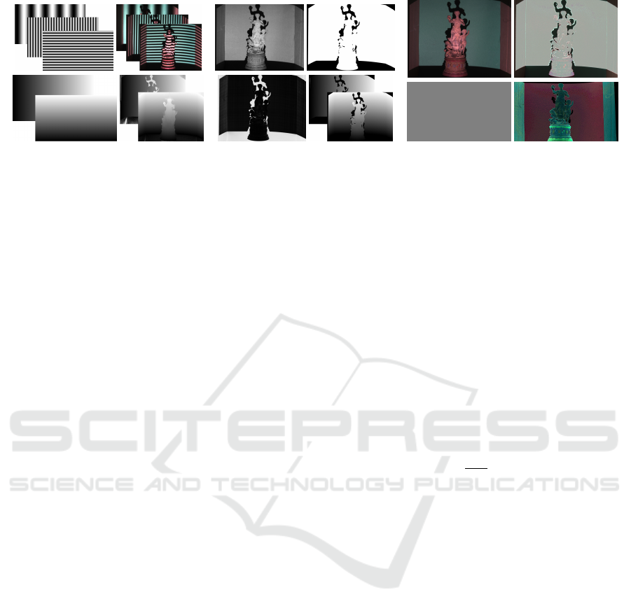
(a) Camera-Projector Correspondences (b) Masking Erroneous Phase (c) Inverse Texture Projection
Figure 2: Examples of sinusoidal fringe patterns and thus illuminated scenes captured by a camera (a, top). Horizontal and
vertical phases of the projector and the camera calculated from the fringe images (a, bottom). Texture image calculated
from averaging captures (4) and error image calculated from (9) (b, left). Projection mask clustered from error image and
correspondingly masked phase images (b, right). Textures T projected onto an exemplary scene: Gray projection and inverse
texture calculated with Algorithm 1 (c, bottom). Correspondingly captured scene without and with color correction (c, top).
Projecting T on the scene approximates an uncolored
grayish scene as visualized in Figure 2 (c).
Theoretically, an optimal texture T solution (2)
can be calculated explicitly from at least two captured
images. However, this is not recommended from a
practical point of view. This is due to the following
phenomena, which cannot be considered in the un-
derlying model (1):
• Color cross-talk between the different color chan-
nels of projector and camera.
• Scattered light from one pixel to others are not
considered, since it only takes into account direct
pixel to pixel correspondences.
• Specular or absorbing materials, leading to
clipped values in the captured image, due to a lim-
ited dynamic range.
3.1 Iterative Color Equalization
To solve problem (2), we propose an iterative method
that is robust against the irregularities listed above.
We combine alternate updates of the projected texture
T and the equalized target value
¯
I with a logarithmic
search that uses the limited range of projector pixel
values (8-bit in[0,255]). In this way, a stable conver-
gence of the process is achieved after a few iterations.
Logarithmic Search. We assume that we have
direct correspondences between camera and
projector pixels that are given by a mapping
P : (x
I
, y
I
) → (x
P
, y
P
) that assigns a corresponding
projector pixel (x
P
, y
P
) to each image pixel (x
I
, y
I
).
Therewith, any projection pixel T
i j
in the captured
scene is known to be located at P (T
i j
) in the projector
input image. Since these are usually limited to
8-bit color values in three color channels, we have a
discrete search range for texture values of T that can
be effectively used by a binary search. Moreover,
projecting light is a monotonous procedure, therefore
increasing values of T
i j
lead to increasing values of
I
i j
. In order to implement and exploit this knowledge,
the values of the projection P (T ) are adjusted via a
logarithmic search until the error (2) of the resulting
image I = I
0
+ I
00
◦ T to the equalization value
¯
I for
all pixels is minimal.
Equalization Value. Minimizing energy (2) with a
fixed texture T leads to an optimal equalization value
¯
I =
1
MN
∑
i j
I
i j
(3)
given by the mean of image I
M×N
.
Alternating updates of the inverse texture T and
the equalization value
¯
I with adjusted increments lead
to Algorithm 1, which already converges after 7 it-
erations in case of standard 8-bit projective devices.
Since the texture update is pixel-wise independent,
the individual iterations can be implemented effi-
ciently. Figure 2 (c) shows a scene balanced in this
way. Each iteration was applied separately to the dif-
ferent color channels to intercept the color cross-talk.
3.2 Camera-projector Correspondences
In order to apply Algorithm 1, a reliable mapping
P (·) as described in Section 3.1 is required. A rec-
ommended approach for determining close point cor-
respondences between projector image and camera
image is the structured light approach introduced in
(Zhang and Huang, 2004). The projection of phase-
shifted sine waves (Figure 2, (a), top) allows the cal-
culation of phase images encoding the scene through
the projection (Figure 2, (a), bottom). This usually re-
quires phase unwrapping methods like (Bioucas-Dias
Iterative Color Equalization for Increased Applicability of Structured Light Reconstruction
727

and Valadao, 2007) or (An et al., 2016) to encode gen-
erated wrapped phases. The phase information can be
used to determine point correspondences of projector
and camera pixels. Errors in the underlying phase in-
formation can be caused by
• Overexposed or underexposed areas in the scene
where the projected fringes are not visible.
• Regions in the scene that are visible to the camera
but not to the projector.
• Shadows cast by the illuminated object.
Masking Erroneous Phase Values. For the success
of the proposed color equalization method it is a pre-
requisite to have an accurate mapping P available. No
false correspondences should be used that would sig-
nificantly falsify the result. For this purpose, incorrect
phase information should be masked out beforehand.
Defective phase regions, which are calculated using
standard phase shift approaches (Malacara, 2007),
are usually much more noisy than correctly coded
ones. Therefore, gradient based filters are typically
used to mask out erroneous regions. However, these
approaches are not sufficiently accurate for the pre-
sented application. Due to the gradient dependency,
edges are falsely masked out, which runs counter to
the later goal of reconstructing highly accurate small
structures. In order to create an appropriate mask-
ing, a simple method is presented that provides much
more accurate results. Given is the basic property of
phase-shifted sinusoidal patterns:
1
N
N
∑
n=1
I
H
n
=
1
M
M
∑
m=1
I
V
m
= I
0
+ 0.5I
00
. (4)
The sum of the phase-shifted sine waves results in
zero, which neglects their influence. This means that
the applied illumination of the scene in sum is equiv-
alent to a uniform grey projection. Let I
H
n
and I
V
n
denote the captured scenes, illuminated by respective
sine patterns P
H
n
and P
V
m
, defined by
P
H
n
(i, j ) = sin
2π j
w
F
H
+
2π(n − 1)
N
(5)
P
V
m
(i, j ) = sin
2πi
h
F
V
+
2π(m − 1)
M
(6)
i =1, ..., h, j = 1, ..., w, n = 1, ..., N, m = 1, ..., M
with F
H
and F
V
being the number of horizontal and
vertical fringes over the projection and w and h the
projector’s image width and height in pixels.
If the scene was captured without illumination, I
0
is already given and so I
00
can be estimated by
I
00
=
1
N
N
∑
n=1
I
H
n
+
1
M
M
∑
m=1
I
V
m
− 2I
0
. (7)
Finally, we can calculate an error E of the horizontal
and vertical phase values Φ
H
and Φ
V
to the captured
images I
H
n
and I
V
m
by
E =
N
∑
n=1
sin
Φ
H
F
H
+
2π(n−1)
N
−
I
H
n
−I
0
I
00
2
(8)
+
M
∑
m=1
sin
Φ
V
F
V
+
2π(m−1)
M
−
I
V
m
−I
0
I
00
2
.
Figure 2 (b, top left) shows an example of a texture
computed from image means (4) and (b, bottom left)
the respective error image E from (9). This error re-
liably indicates the quality of the phase values in re-
lation to all captured images of the scene. Since erro-
neous phase values produce much higher errors than
correct ones, a high-quality mask can be generated by
applying k-Means Clustering to error image E. Note
that bi-clustering can be efficiently implemented in
O(MNlog(MN)). Figure 2 (b, top right) shows the
final mask as a result of k-means clustering applied
with two clusters. Figure 2 (b, bottom right) shows
the final masked phases.
Algorithm 1: Iterative Color Equalization.
Input: Camera-projector correspondences P .
1: Initialize projection texture P (T
(0)
i j
) = 128 ∀i j.
2: Project pattern T
(0)
i j
and capture lit scene I
(0)
.
for z = 1, ..., 7
3:
¯
I
(z−1)
=
1
MN
∑
i j
I
(z−1)
i j
4: P (T
(z)
i j
) =
P (T
(z−1)
i j
) + 2
7−z
, I
(z−1)
i j
<
¯
I
(z−1)
P (T
(z−1)
i j
) − 2
7−z
, I
(z−1)
i j
>
¯
I
(z−1)
P (T
i j
), else
5: Project pattern T
(z)
and capture resulting scene I
(z)
.
end
Output: Inverse texture T .
4 INVERSELY TEXTURING
STRUCTURED LIGHT (ITSL)
In order to neglect color influences on the geometry
estimation by the structured light approach, we com-
bine the inverse texture calculated by Algorithm 1
with the fringe images P
H
n
and P
V
m
from (5) and (6).
Instead of the normal patterns we project the Inversely
Texturing Structured Light Patterns (ITSLP)
T
H
n
= P
H
n
◦ P (
˜
T ), n = 1, ..., N (9)
T
V
m
= P
V
m
◦ P (
˜
T ), m = 1, ..., M. (10)
We lift values of the inverse texture close to zero to
avoid that no fringes are projected in these regions
VISAPP 2020 - 15th International Conference on Computer Vision Theory and Applications
728
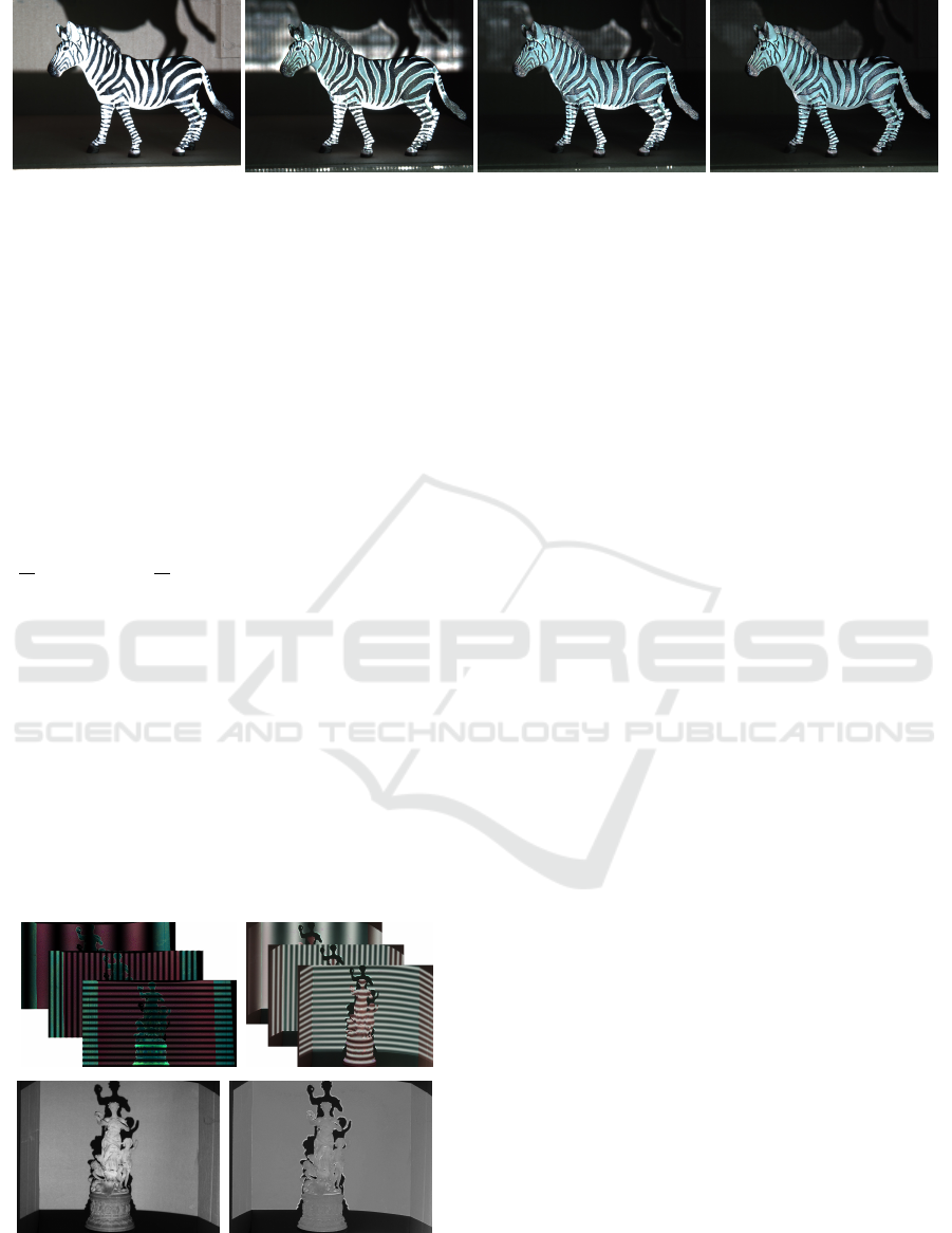
Figure 3: Captured scene of a zebra to visualize the improvements of several iterations of ITSL to color equalization. Normal
image (left) and equalized captures after one, two and three iterations (second left to right).
after multiplication:
˜
T
i j
=
(
T · T
i j
, if T
i j
> 0.05 · max(T )
0.05 · max(T ) , else
(11)
In the process, masked areas are also coded after sev-
eral iterations of the approach.
An important feature of ITSLP is that they fulfill
the basic property for fringes of a structured light sys-
tem, as mentioned in (4). In the new case we have for
every scene
1
N
N
∑
n=1
I
H
n
= I
0
+
1
N
N
∑
n=1
P
−1
(P
H
n
) ◦
˜
T ◦ I
00
(12)
= I
0
+ 0.5(
˜
T ◦ I
00
) ≈ I
0
+ 0.5(T ◦ I
00
). (13)
This is equivalent to usual structured light patterns
being projected onto a grey scene without color in-
fluence. Figure 4 (top left) shows ITSLP, computed
by (11) and the patterns projected onto the scene
(top right). For further visualization Figure 4 (bot-
tom) shows the scenes after averaging (4) the standard
structured light patterns (left) and ITSLP (right).
Each iteration of ITSLP increases the quality of
the reconstructions. Regions with incorrect phase in-
formation of the first iteration can be corrected by
multiple iterations of ITSL.
Figure 4: Examples of inversely texturing fringe images
projected by the projector (top left) and illuminated scene
(top right). Textures calculated by (7) from the fringe im-
ages (bottom).
5 EVALUATION
In order to evaluate the usefulness of the method pre-
sented, we carry out some quantitative and qualitative
tests. First the performance of the color equalization
from Algorithm 1 is examined. In particular, the be-
havior after several iterations of ITSL is investigated.
Subsequently, we show the advantages and the impor-
tant practical benefits of ITSLP to structured light re-
construction. In several scenarios, in which the stan-
dard structured light approach usually fails, the ben-
efits, which arise from the new, improved approach,
become clear.
5.1 Inverse Projection Texture
Figure 6 (left) shows a captured image of a standard-
ized X-Rite ColorChecker normally used for color
calibration. It consists of 24 calibrated colors that
well cover the entire visual color spectrum. Figure 6
(right) shows the captured checkerboard after an itera-
tion of Algorithm 1. The method applied to this object
demonstrates its behavior in case of very large color
differences in an object’s texture. It is clearly visible
that some color patches (dark red, yellow) cannot be
equalized completely. The reason for this is that light
can only be projected but not removed. If the red,
green or blue component is already in an area above
the mean value of the equalization, it cannot be re-
duced by any projection. To be exact, the gamut of
the camera does not lie in the gamut generated by the
projector. Nevertheless, equalization results of this
quality lead to a significant improvement in the reflec-
tive properties of an object. Moreover, since grayscale
images are sufficient for reconstruction, monochrome
cameras can also be used. Errors that may occur dur-
ing color equalization due to inconsistent gamuts are
negligible in this case. Multiple iterations of ITSL,
further improve the quality of equalization. Figure 6
shows the behavior of the Root-Mean-Squared-Error
(RMSE), referred to the mean value (3), for an iter-
ative application. While after the first iteration the
RMSE decreases by more than 90%, the following it-
Iterative Color Equalization for Increased Applicability of Structured Light Reconstruction
729
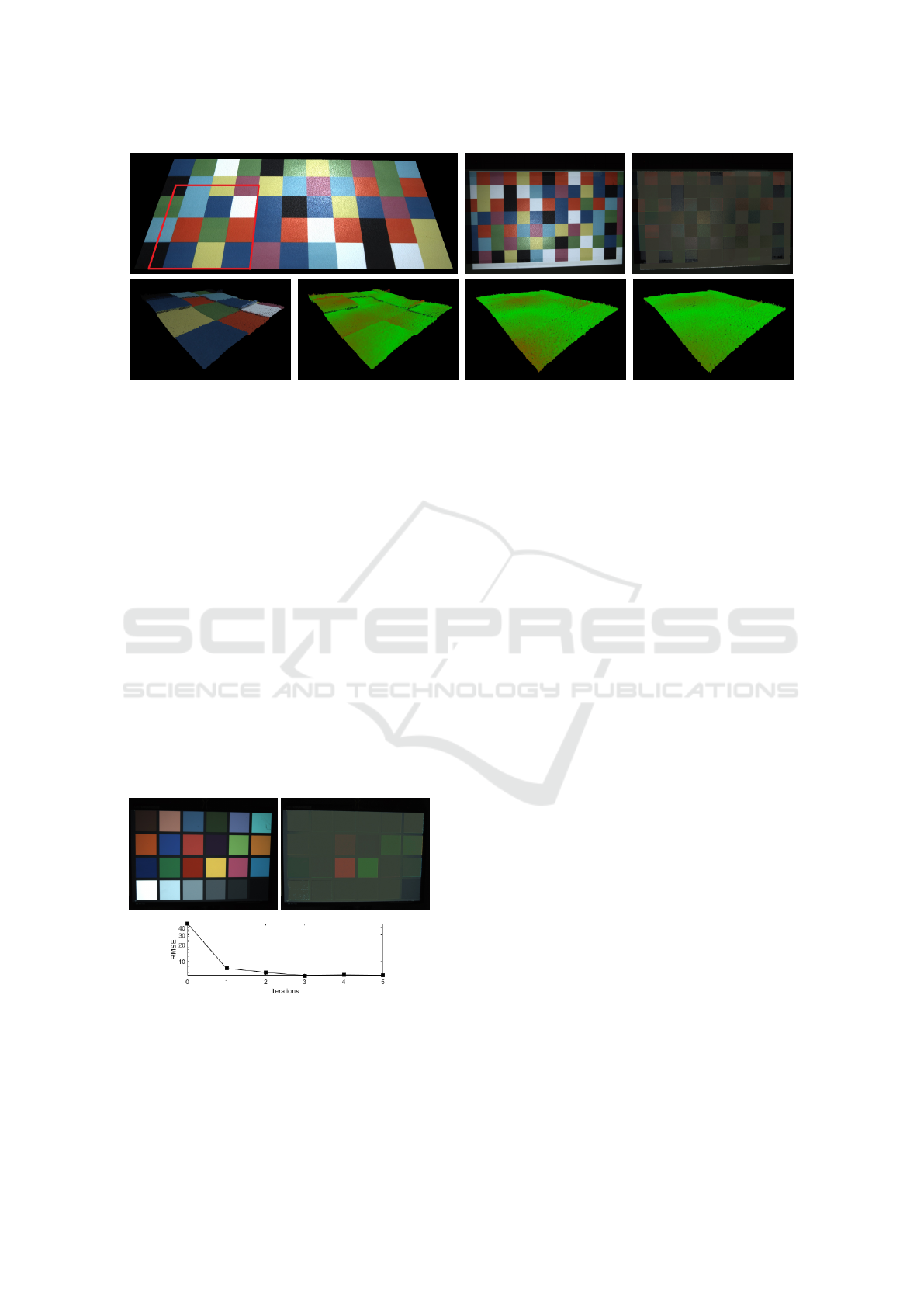
Figure 5: Flat colored checkerboard: Initial reconstructed point cloud (top left), normal texture (top middle) and equalized
texture after one iteration of ITSL (top right). Enlarged marked area of point cloud (bottom left) and point clouds before and
after two iterations of the proposed approach (bottom second left to right).
erations reduce this error only slightly in this case.
However, these minor changes can lead to a dra-
matic improvement of reconstructions. In particular,
the reflection behaviour at edges of strongly contrast-
ing areas can be significantly improved after a few
iterations, due to lower radiation. For visual evalua-
tion, Figure 3 shows several iterations of the method
applied to a figurine of a zebra. The coloration of
this object contains maximally strong edges in the
transitions from black to white areas. Due to better
approximated phase values, every iteration improves
the equalization quality. Note that limited projector
brightness and stray light between pixels are the rea-
sons why it is impossible to achieve complete equal-
ization in an extreme scenario like the one shown in
Figure 3. But within the scope of the possibilities, the
result obtained here is by far sufficient to yield signifi-
cant improvements in reconstruction, as demonstrated
later on.
Figure 6: Captured image of a X-Rite ColorChecker before
(top left) and after one iteration of color equalization with
Algorithm 1 (top right). RMSE of color equalization for
several iterations of ITSLP (bottom).
5.2 Inversely Texturing Structured
Light
In order to demonstrate the advantages of the pre-
sented method in the context of 3D reconstruction,
we will apply it in the following exemplary scenarios.
We show quantitative and qualitative improvements in
the important case of high-precision reconstruction of
very small structures. We then apply it to objects with
high-contrast staining, such as the one in Figure 3,
and qualitatively investigate the behavior after several
iterations of the method. Finally, the chances arising
from the method in context of specular and reflecting
objects are shown by an exemplary reconstruction of
a shiny metal sphere.
5.2.1 High-precision Reconstruction
Different colors of an object’s texture reflect different
wavelengths of light. These specific properties, de-
pending on the object coloration, cause projected pat-
terns in structured light applications to be reflected in
slightly different ways. Therefore, depending on the
coloration of an object, slightly different depth values
are estimated. Usually, this effect is very small, com-
pared to the geometry of an object, and can therefore
be neglected. However, in high-precision 3D recon-
structions, as for example encountered in quality con-
trol setups, this problem has considerable effects and
significantly distorts the results, especially in high-
contrast regions.
In order to evaluate the usefulness of the proce-
dure in relation to this problem, we apply it to a
flat checkerboard with patches of different colors, as
shown in Figure 5. The checkerboard is absolutely flat
and any differences in the depth of the reconstruction
are errors due to the different colors of the patches.
VISAPP 2020 - 15th International Conference on Computer Vision Theory and Applications
730

Figure 7: Average Euclidean depth error in µm of recon-
structed point cloud for several iterations of ITSL.
Figure 5 (top left) shows the reconstructed point cloud
resulting from the standard structured light approach.
For further visualization, Figure 5 (top center, right)
shows the captured scene before and after color equal-
ization. To demonstrate the problem more clearly,
Figure 5 (bottom left) shows an enlarged version of
the marked area.
Figure 5 (bottom, second left) shows the point
cloud of the enlarged region without texture informa-
tion, but colored by the Euclidean error with respect
to the flat ground truth. Finally, Figure 5 (bottom,
second right and right) shows the reconstructed re-
gions after one and two iterations of ITSL. To make a
qualitative evaluation possible, the depth value of the
checkerboards is enhanced by a factor of 3 for visual-
ization. This clearly shows the improvements of the
method presented.
Besides the qualitative evaluation, we demonstrate
the benefit by a quantitative error measurement. Fig-
ure 7 shows the behavior of the average depth error
of the reconstructed point with respect to the ground
truth. Multiple iterations improve the quantitative er-
ror continuously. Nevertheless, since the improve-
ments are in the range of µm, one should decide
whether the improvement of accuracy of the recon-
struction justifies higher additional expenses in the
specific case.
5.2.2 High-contrast Colored Objects
Another important field of application of the method
is the reconstruction of objects with extremely un-
favourable colouring. The statue of a zebra from Fig-
ure 3 is treated as an example. Due to the very bright
and very dark areas there is no camera setting that
allows a complete encoding of the surface with struc-
tured light. Figure 8 (left) shows the result of standard
structured light with a rather short exposure time. The
white areas of the zebra are well reconstructed, while
the black areas are underexposed and not encoded by
the patterns. Conversely, Figure 8 (middle) shows the
reconstructions at a higher exposure time, which al-
lows the reconstruction of the black areas, but over-
exposes the white regions. Finally, Figure 8 (right)
shows the result of ITSL. Already one iteration can
solve the problem caused by the color contrasts and
allows the reconstruction of the entire surface. Fur-
Figure 8: Reconstructed point clouds of a zebra statue. Top
row and bottom row show the same point clouds with and
without color information. Left and middle columns show
results of standard structured light in case of over and under-
exposed images. Right shows ITSL handling the proposed
problems.
ther iterations improve the quality slightly, but they
should again be weighed according to the benefit and
the recording time spent.
5.2.3 Specular Objects
As last and most important field of application of the
method, we show its benefits in structured light recon-
struction of specular objects. We apply the method
to a specular metal sphere that strongly reflects the
light emitted by the projector. The resulting high-
lighted areas are overexposed and cannot be encoded
by the projected patterns. This effect cannot be com-
pletely avoided, but it can be greatly reduced. Figure
9 shows the reconstructed point clouds with standard
structured light (left) and after one and two iterations
of ITSL (center and right).
The highlighted points do not only depend on the
projector’s position relative to the object, but also on
the camera perspective. To illustrate that the overex-
posed point is different for different camera positions,
the point clouds in Figure 9 are triangulated from a
pair of cameras instead of a camera-projector pair.
Therefore, there are two independent faulty holes in
the reconstructed point clouds from Figure 9. Finally,
we would like to point out that this property means,
that the defective area of the phase of one camera
is most likely correctly encoded in the other camera.
This can be used to improve reconstructions and to
make them invariant to reflective objects in multiple
camera structured light setups, as they are typical for
practical applications.
6 CONCLUSION
In this paper, we have presented a method that greatly
expands the practical scope of structured light re-
construction. Typical scenarios, in which the stan-
dard approach usually fails, are now treatable. Un-
Iterative Color Equalization for Increased Applicability of Structured Light Reconstruction
731
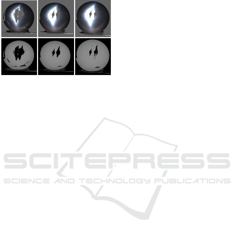
Figure 9: Triangulated point clouds of a specular sphere,
captured from two views. Standard structured light (left)
and results of ITSL after one and two iterations (middle and
right). The top row shows the textured point clouds, while
the bottom row visualizes the sole geometry.
favorably colored and reflective objects present no or
significantly fewer problems. In the area of high-
precision reconstruction, a significant leap in accu-
racy is achieved. However, the iterative character of
the method also increases the recording time. Sev-
eral iterations increase the accuracy, but should be
weighed against the additional time required. There-
fore, the approach is designed so that it can be eas-
ily built on existing setup and applied or omitted as
needed.
REFERENCES
An, Y., Hyun, J.-S., and Zhang, S. (2016). Pixel-
wise absolute phase unwrapping using geometric con-
straints of structured light system. Optics express,
24(16):18445–18459.
Bioucas-Dias, J. M. and Valadao, G. (2007). Phase unwrap-
ping via graph cuts. IEEE Transactions on Image pro-
cessing, 16(3):698–709.
Donlic, M., Petkovic, T., and Pribanic, T. (2015). 3d surface
profilometry using phase shifting of de bruijn pattern.
In Proceedings of the IEEE International Conference
on Computer Vision, pages 963–971.
Fetzer, T., Reis, G., and Stricker, D. (2019). Robust auto-
calibration for practical scanning setups from epipolar
and trifocal relations. In 2019 16th International Con-
ference on Machine Vision Applications (MVA), pages
1–6. IEEE.
Gupta, M., Yin, Q., and Nayar, S. K. (2013). Structured
light in sunlight. In Proceedings of the IEEE Inter-
national Conference on Computer Vision, pages 545–
552.
Hartley, R. and Zisserman, A. (2003). Multiple view geom-
etry in computer vision. Cambridge university press.
Lourakis, M. I. and Deriche, R. (2000). Camera self-
calibration using the kruppa equations and the svd of
the fundamental matrix: The case of varying intrinsic
parameters.
Malacara, D. (2007). Optical shop testing. John Wiley &
Sons.
Nayar, S. K., Krishnan, G., Grossberg, M. D., and Raskar,
R. (2006). Fast separation of direct and global com-
ponents of a scene using high frequency illumination.
In ACM Transactions on Graphics (TOG), volume 25,
pages 935–944. ACM.
O’Toole, M., Mather, J., and Kutulakos, K. N. (2014).
3d shape and indirect appearance by structured light
transport. In Proceedings of the IEEE Conference
on Computer Vision and Pattern Recognition, pages
3246–3253.
O’Toole, M., Raskar, R., and Kutulakos, K. N. (2012).
Primal-dual coding to probe light transport. ACM
Trans. Graph., 31(4):39–1.
Petkovi
´
c, T., Pribani
´
c, T., and Ðonli
´
c, M. (2016). Single-
shot dense 3d reconstruction using self-equalizing de
bruijn sequence. IEEE Transactions on Image Pro-
cessing, 25(11):5131–5144.
Sansoni, G. and Redaelli, E. (2005). A 3d vision system
based on one-shot projection and phase demodulation
for fast profilometry. Measurement Science and Tech-
nology, 16(5):1109.
Weinmann, M., Schwartz, C., Ruiters, R., and Klein,
R. (2011). A multi-camera, multi-projector super-
resolution framework for structured light. In 2011
International Conference on 3D Imaging, Modeling,
Processing, Visualization and Transmission, pages
397–404. IEEE.
Yang, L., Li, F., Xiong, Z., Shi, G., Niu, Y., and
Li, R. (2017). Single-shot dense depth sensing
with frequency-division multiplexing fringe projec-
tion. Journal of Visual Communication and Image
Representation, 46:139–149.
Zhang, L., Curless, B., and Seitz, S. M. (2002). Rapid shape
acquisition using color structured light and multi-pass
dynamic programming. In Proceedings. First Inter-
national Symposium on 3D Data Processing Visual-
ization and Transmission, pages 24–36. IEEE.
Zhang, S. and Huang, P. (2004). High-resolution, real-time
3d shape acquisition. In 2004 Conference on Com-
puter Vision and Pattern Recognition Workshop, pages
28–28. IEEE.
Zhang, S. and Huang, P. S. (2006). High-resolution, real-
time three-dimensional shape measurement. Optical
Engineering, 45(12):123601.
Zhang, S. and Yau, S.-T. (2008). Three-dimensional shape
measurement using a structured light system with dual
cameras. Optical Engineering, 47(1):013604.
Zhang, Z. (1998). Determining the epipolar geometry and
its uncertainty: A review. International journal of
computer vision, 27(2):161–195.
VISAPP 2020 - 15th International Conference on Computer Vision Theory and Applications
732
