
A Model based Toolchain for the Cosimulation of Cyber-physical
Systems with FMI
David Oudart
1,2
, J
´
er
ˆ
ome Cantenot
1
, Fr
´
ed
´
eric Boulanger
3
and Sophie Chabridon
2
1
EDF R&D, Palaiseau, France
2
SAMOVAR, CNRS, T
´
el
´
ecom SudParis, Institut Polytechnique de Paris, France
3
LRI, CNRS, CentraleSup
´
elec, Universit
´
e Paris-Saclay, France
Keywords:
Cosimulation, FMI, IT, MDE, Smart Grid, Cyber-physical System.
Abstract:
Smart Grids are cyber-physical systems that interface power grids with information and communication tech-
nologies in order to monitor them, automate decision making and balance production and consumption. Cosi-
mulation with the Functional Mock-up Interface standard allows the exploration of the behavior of such com-
plex systems by coordinating simulation units that correspond to the grid part, the communication network
and the information system. However, FMI has limitations when it comes to cyber-physical system simula-
tion, particularly because discrete-event signals exchanged by cyber components are not well supported. In
addition, industrial projects involve several teams with different skills and methods that work in parallel to
produce all the models required by the simulation, which increases the risk of inconsistency between models.
This article presents a way to exchange discrete-event signals between FMI artifacts, which complies with the
current 2.0 version of the standard. We developed a DSL and a model-based toolchain to generate the artifacts
that are necessary to run the cosimulation of the whole system, and to detect potential inconsistencies between
models. The approach is illustrated by the use case of an islanded grid implementing diesel and renewable
sources, battery storage and intelligent control of the production.
1 INTRODUCTION
Strong and fast evolutions of the electric landscape
deeply impact the existing power grids. Electric vehi-
cles, decentralized and renewable production as well
as political considerations require the grid operators
to continuously adapt their operating strategy and the
grid equipments. Smart Grid is the name given to the
oncoming generation of power grids, augmented with
information and communication technologies. Such
systems aim to allow prevention, better reactivity and
improved response to electrical events such as fail-
ures, but also ensure proper interoperability between
all the components of the grid. Because they may im-
pact a large amount of people, smart grids are critical
systems so they require thorough verification and val-
idation before their implementation. To this end, sim-
ulation is very valuable to evaluate various behavioral
assumptions (Palensky et al., 2017).
As they involve many interdependent technical
domains, namely electronics, software information
processing and telecommunications, smart grids are
a typical example of Cyber-Physical System (CPS),
with the same challenges to face when it comes to
modeling and simulation. Designing a CPS usu-
ally involves several teams working simultaneously
on modeling multiple aspects of the system. Inter-
connecting these models implies to deal with hetero-
geneous models of computation, data consistency is-
sues, discrete and continuous variabilities, and va-
rious time-steps (Muller et al., 2018). The lack of
mature smart grid simulation tools lead Rohjans et
al (Rohjans et al., 2014) to establish a list of require-
ments for an appropriate tool addressing these chal-
lenges.
In addition, industrial companies are reluctant to
changes in their work methods and tools, and prefer to
rely on the existing skills and strengths of their teams.
Simulating CPS amounts to find ways and tools to
model and simulate interactions between discrete and
continuous models, taking the most from the existing
skills of the industrial teams who are developing these
systems.
Cosimulation approaches allow each one of the
teams involved in the modeling phase to use their
own language and tool of predilection, as well as the
most suited paradigm for their domain. There are se-
veral standards for cosimulation, and the Functional
Oudart, D., Cantenot, J., Boulanger, F. and Chabridon, S.
A Model based Toolchain for the Cosimulation of Cyber-physical Systems with FMI.
DOI: 10.5220/0008875400150025
In Proceedings of the 8th International Conference on Model-Driven Engineering and Software Development (MODELSWARD 2020), pages 15-25
ISBN: 978-989-758-400-8; ISSN: 2184-4348
Copyright
c
2022 by SCITEPRESS – Science and Technology Publications, Lda. All rights reserved
15

Mockup Interface (FMI)
1
, is particularly suited to in-
dustrial projects.
Our main objective is to provide a toolchain to
help modeling teams to create interoperable mo-
dels. For that purpose, we developed a Domain Spe-
cific Language (DSL) and we rely on MDE prac-
tices to automatically generate wrappers, interfaces
and deployment scripts compliant with the FMI stan-
dard, and handling the continuous-discrete intercon-
nections. This minimizes the effort required from the
model developers to adapt the models, and reduces
the risk of errors and the deployment cost of each it-
eration.
In the next section, we explain why we chose FMI
for the cosimulation of smart grids and the limitations
of this choice. In Section 3, we propose a way to deal
with the limitations of FMI for discrete signals. Sec-
tion 4 presents our toolchain to build the simulation
of a CPS, dealing with the industrial and FMI cons-
traints. Section 5 illustrates the approach on a use
case. Section 6 presents scenarios to validate our ap-
proach.
2 STATE OF THE ART
In the electrical energy community, the challenge of
simulating smart grids is not new (Li et al., 2011,Nu-
taro, 2011, Yang et al., 2013). However, it usually
consists in the interaction of two domains via two dy-
namic models. The problem of the synchronization
of models and of their consistency is not specifically
addressed by these approaches, but is not really chal-
lenging when limited to two domains.
For the industrial simulation of complex systems
and CPS, it is better to rely on standard technologies,
as they address various needs like scalability, modu-
larity or reusability. The Functional Mockup Interface
(FMI) (Blochwitz et al., 2011) and The High Level
Architecture (HLA) (Dahmann and Morse, 1998) are
two interoperability approaches allowing the inter-
connection of several different simulators in an inte-
grated execution.
If both approaches have been declared as standard,
FMI benefits from a stronger popularity with more
than 80 compatible tools
2
. Its ability to protect in-
dustrial property inside FMUs makes it very attrac-
tive for industrial projects and makes collaborative
design easier (Gomes et al., 2018b). FMI defines a
simulation unit format called Functional Mockup Unit
(FMU), which embeds a model and an execution en-
1
https://fmi-standard.org
2
https://fmi-standard/tools/
gine along a standard interface to control the execu-
tion of the simulation. FMI cosimulations are driven
by a master algorithm, which synchronizes the exe-
cution of the FMUs and the exchange of data at some
communication points.
Because a time-step between two communication
points can not be null, FMI is not particularly adapted
to reactive systems and discrete-event modeling. Cur-
rent works already propose FMI extensions, such as
zero-size steps (Guermazi et al., 2015,Cremona et al.,
2019), or absent values (Cremona et al., 2019) to han-
dle discrete-event signals. Optimized master algo-
rithms (Tavella et al., 2016, Van Acker et al., 2015)
can increase the precision of the simulation while still
being compliant with the standard, by trying to lo-
cate the occurrence of an event using the optional roll-
back FMI feature (reverting the state of an FMU to a
previous communication point), or by optimizing the
choice of the time step, which requires FMUs to be
exported as white boxes.
Moreover, connections between FMUs are defined
statically before execution, meaning that every pos-
sible interaction between models has to be defined
during the modeling phase and the cosimulation set
up. This can lead to many revisions and iterations
on the models while trying to interoperate them with
the other models, and potentially generate a lot of in-
put/output ports to cover all possible scenarios. Adap-
tation approaches (Gomes et al., 2018a) allow the
reuse of existing models or FMUs by wrapping them
in a simulation unit adapted to a particular cosimula-
tion.
This last issue is derived from the fact that com-
plex system design involves several viewpoints from
different technical domains, therefore several hetero-
geneous models developed by different teams. Mo-
del driven approaches are used in industry to inter-
connect these models and represent the consistency
links between them (Zhao et al., 2017, Suri et al.,
2017, Andr
´
en et al., 2017). These approaches mainly
aim to facilitate the final system realisation, but only
few of them include the simulation in the design pro-
cess (Paris et al., 2017).
FMI offers a technological means to simulate a
CPS such as a smart grid, but requires a support-
ive method and/or tool to address the various issues
raised. The toolchain we developed supports model
transformations and focuses on the deployment of a
correct cosimulation platform. It complies with the
FMI standard and relies on existing tools which im-
plement it, but also supports exchange of discrete-
event signals, as smart grids involve cyber compo-
nents. It provides a domain specific language to al-
low the modeling teams to identify and characterize
MODELSWARD 2020 - 8th International Conference on Model-Driven Engineering and Software Development
16

all signals exchanged between FMUs in a cosimula-
tion. Finally, it automates the generation of simula-
tion artifacts implementing these interfaces, such as
configuration files, execution scripts and model adap-
tators.
3 HOW TO EXCHANGE
DISCRETE SIGNALS
BETWEEN MODELS VIA FMI
FMI is designed for the interconnection of simulators
producing continuous signals. Therefore, for simula-
tions involving information processing and commu-
nication networks, which rely on discrete events, we
need to encode such sporadic events using continuous
signals.
3.1 Problem and Definitions
We suppose the set V of all the values a signal can
take is one of the following sets: R, Z, S the set of
all string values, or B the set of all boolean values
{true, false}.
A discrete-event signal can then be represented
as a function of time x
DE
: E → V where E ⊂ R
+
is
the discrete set of the event-firing points.
The problem is that signals in an FMI cosimu-
lation are only considered at some communication
points chosen by the master. The set C of the com-
munication points being independent of the set E, if
we want to exchange a discrete event as an FMI si-
gnal, we have a risk of undefined or missed events:
• E ∩ C ⊂ C: at some communication point, the
value of the signal is not defined. (pb. 1)
• E ∩ C ⊂ E : some events are missed by the master
of the cosimulation and the other FMUs (pb. 2)
The three possible cases are illustrated in Figure 1.
E C
missed
OK
undefined
Figure 1: Differents cases for discrete event signals.
3.2 Proposed Solution
In order to be sure that the exchanged signal is defined
on every communication points and avoid pb. 1, we
need an FMU to produce a time-continuous signal
defined on R
+
(at least bounded by the start and stop
times of the cosimulation).
We propose an encoding component to transform
a discrete signal into two time-continuous signals
which can be exchanged over FMI. The first time-
continuous signal keeps the value of the last event
emitted until a new event is emitted. But we need
a second coupled signal to express that an event ac-
tually has been emitted, in order to detect sequences
of events having the same value. Indeed, each time
the value of our first signal changes we know that an
event has occurred, but while it is constant we cannot
detect if there has been an event with the same value
or no event.
Following these principles, we also provide a de-
coding component to perform the reverse operation
and obtain the discrete-event signal from the FMI dis-
cretization of the time-continuous signals.
3.2.1 Encoding Component
Input: x
DE
a discrete-event signal. Output: x and x
s
two time-continuous signals.
We consider E = {te
1
,te
2
, . . . } as ordered.
∀t ∈ R
∗
, t ≥ te
1
(
x(t) = x
DE
(te
n
t
)
x
s
(t) = n
t
where n
t
= max{i | te
i
≤ t} is the index of the last
event that occurred before or at time t.
When t < te
1
, no event has been emitted yet, and
x
s
(t) = 0. x(t) can have any value, which will be
ignored by the decoding component. We suggest to
choose an initial value corresponding to the last event
which could have occurred before the start of the sim-
ulation. When it is not possible or does not make
sense, a default value in the V set (0, an empty string
or false) is a valid choice too.
3.2.2 Decoding Component
Input: y and y
s
two time-continuous signals sampled
over C . Output: y
DE
a discrete-event signal.
C = {tc
0
,tc
1
,tc
2
, . . . } is the set of the communi-
cation points. We assume the previous definition of
the set E , and the fact that y and y
s
are the x and x
s
si-
gnals discretized by the FMI cosimulation master on
C .
We define the discrete set F ⊂ R
+
as the set of
the time points of the y
s
’s “rising edges”. These
time points are all synchronized with a communica-
tion point so we have:
F =
tc
i
∈ C
i > 1 , y
s
(tc
i
) > y
s
(tc
i−1
)
i = 0 , y
s
(tc
0
) 6= 0
A Model based Toolchain for the Cosimulation of Cyber-physical Systems with FMI
17

Then the output of our component is:
y
DE
: F → V
∀i , tc
i
∈ F ⊂ C y
DE
(tc
i
) = y(tc
i
) = x
DE
(te
n
tc
i
)
where n
tc
i
and te
n
tc
i
∈ E are defined as before as the
index of the last event occurring before or at time tc
i
,
and the time of this event.
3.3 Discussion
We are aware that several challenges still need to be
addressed in order to allow discrete-event signal ex-
changes over FMI. The dates of the events are almost
always approximated from the global cosimulation
perspective. It prevents a rigorous handling of concur-
rent events for instance. For this issue, we are limited
by the definition of time in the FMI standard (Broman
et al., 2015). Our goal is to allow a better support of
the discrete-event signals with a minimal adaptation
effort.
Using our two components to encode and decode
a discrete-event signal between two FMUs, and using
the same notation as previously, an event received at
tc
i
has been emitted at te
n
tc
i
. We know that te
n
tc
i
is
the latest time point of E such as tc
i−1
< te
n
tc
i
≤ tc
i
.
So our solution addresses pb. 2 by ensuring that
if an event is not synchronized with a communica-
tion point, it can still be detected, but delayed by
tc
i
− te
n
tc
i
. This is an inherent limitation of the cur-
rent version 2.0 of FMI.
te
1
te
2
te
3
te
4
tc
i−1
tc
i
=
te
n
tc
i
missed occurrence
Figure 2: Missing events that are too close.
However, pb. 2 is not completely addressed, as
events emitted between tc
i−1
and te
n
tc
i
are still missed
as shown in Figure 2. We can only express at most
one event at each communication point. It is an arbi-
trary choice by only considering the last emitted one
in the time-step interval. Nonetheless, the difference
between y
s
(tc
i
) and y
s
(tc
i−1
) still reveals the number
of events emitted since the last communication point.
A smart-enough cosimulation master might decide to
cancel the last step and replay it with a smaller step
in order to catch the missed events. This requires the
optional rollback functionality of the FMI standard.
Finally, the use of these components in the FMU
models requires potentially heavy changes to the orig-
inal models, as well as the addition of FMI connec-
tions dedicated to the synchronization of FMUs. This
kind of knowledge is specific to the cosimulation pro-
cess and does not need to be the concern of the mod-
eling teams.
The toolchain presented in Section 4 provides
methods and tools to generate these components for
the modeling teams, and to automate the deployment
and the possible iterations of the smart grid cosimula-
tion model.
4 TOOLCHAIN PRESENTATION
4.1 An Approach based on Model
Refinement
One of the main advantages of using a cosimulation
environment is to allow the different experts to de-
velop their own model in autonomy, with a minimal
interference and in parallel with the others (Gomes
et al., 2018b). The choice of the FMI standard en-
sures the technological compatibility of each simu-
lation unit, or FMU, with the cosimulation environ-
ment, without having to develop a specific connector.
However it does not ensure structural compatibility.
All FMUs produced by the different teams must pro-
vide interoperable data structures, namely each input
should match an output, in type and meaning.
An example of a cosimulation approach for smart
grids (Oudart et al., 2019) identified several steps and
actors involved in such a process. The first step is to
define all the connections between the simulation mo-
dels in order to define the interface of the models for
each modeling team. But the compliance verification
of the models and the creation of the cosimulation ar-
tifacts (FMUs, configuration files) are done by hand,
which make each iteration time-consuming and error-
prone.
The use of a global, architectural model to repre-
sent the structural interfaces of the various simulation
units and the coupling constraints between them, al-
lows the use of syntactic tools to automatically check
some validation rules. It also creates a unique author-
itative artifact to coordinate the work of the various
collaborators, and from which more detailed models
can be derived.
Following this approach, we developed a
toolchain to automate the actions needed to run a
cosimulation starting from a global model. It is
based on model transformations from a platform-
independent model toward simulation artifacts. This
toolchain relies on a domain specific language (DSL),
MODELSWARD 2020 - 8th International Conference on Model-Driven Engineering and Software Development
18

named Cosimulation Modeling Language (CosiML),
to specify the structural interfaces of the simulation
units and the configuration of the cosimulation.
Our choice to develop our own language for this
purpose, instead of choosing an existing one, such as
UML, comes from various reasons :
• in an industrial context, general-purpose lan-
guages like UML are not well mastered outside
the computer science field,
• such languages contain many concepts, but we
only needed a few of them,
• in our approach, adapting UML to model specific
concepts would lead to refining generic concepts
through profiles.
It appeared more efficient to define only what we
needed than to restrict and specialize UML to fit our
needs.
4.2 CosiML, a DSL for Cosimulation
We implemented CosiML inside the Eclipse Model-
ing Framework (EMF) using the Ecore metamodeling
language. Figure 3 shows a simplified metamodel of
CosiML, with the classical elements of every cosimu-
lation.
Figure 3: CosiML simplified metamodel.
CosimulationModel is the root element of the
model, it stores the parameters of the cosimulation
(start time, stop time, time step, etc.) and contains
all the simulation units and their interconnections.
SimulationUnit represents a simulation unit in-
volved in the cosimulation. It contains the Port ele-
ments representing the structural interface of the unit.
Input & Output (Port) represents a port of the
simulation unit. It has a type, an optional default value
and a variability, which is the name used by FMI to
characterize the discrete or continuous nature of si-
gnals.
Link represents a connection between an output
and an input port. A model can be checked to verify
that any two connected ports have the same variabil-
ity, and that they are not contained in the same simu-
lation unit.
There are several kinds of SimulationUnits, as
shown in Figure 4:
ProvidedSimulationUnit is a simulation unit
which is completely provided by the user. Such a
simulation unit is directly usable in the cosimulation
without further action. In our case of FMI cosimu-
lation, a ProvidedSimulationUnit is provided as an
FMU resource and we only have to know the path to
the artifact.
GeneratedSimulationUnit is a simulation unit
which will be generated by the toolchain from a do-
main model. The attribute modelPath stores the path
to the domain model. The format of the model and
the generator to use for the generation of the simu-
lation unit are specific to the tool attribute’s value.
The tool is what is used to build the model, for in-
stance a Java or C++ compiler, or a more complex
modeling tool such as OMNeT for communication
networks. The generator is part of our toolchain, and
will generate the corresponding FMU, which includes
the generation of adapters for discrete event signals.
The generator relies on naming conventions to ac-
cess the elements of the model and adapt them to
the structure of the FMU. For instance, a Java with
a continuous input signal named X should implement
a setX(double value) method. In order to refer to
the model in the generated FMU, the generator uses
two generic attributes: importText defines how to
import the model inside the adapter, and usageText
tells how to use the model. Finally, the attribute
dependencies stores the list of all the resource paths
required by the model (libraries, data files, binaries)
that should be packaged inside the generated simula-
tion unit. Our goal is to stay generic enough to avoid
metamodel modifications when we want to support a
new tool and add a new generator to the toolchain.
For instance, a Java model-based generator would re-
quire:
importText = import package.Classname;
and
usageText = Classname,
whereas a C++ model-based generator would require:
importText = #include "filename.h"
and
usageText = ObjectName.
Scenario a simulation unit generated by the
toolchain from a data file. It only has output ports
and will be used as an independent source of timed
data. The attribute dataPath stores the path to the
data file. We are considering that future versions of
CosiML and the toolchain may support several for-
A Model based Toolchain for the Cosimulation of Cyber-physical Systems with FMI
19

Figure 4: SimulationUnit detailed specializations.
mat, but for now we only support CSV files to be used
as Scenario units.
CSVScenario a particular Scenario element
which refers to a CSV data file. Attributes separator
and decimal defines the characters used respectively
as separator and decimal marker for the CSV content.
4.3 Generation Tools for FMI
Cosimulation
We chose the DACCOSIM NG
3
software to execute
our FMI cosimulation. It implements a master al-
gorithm that is fully compliant with the standard,
with advanced discontinuity detection features, and
intelligent time step strategies (Tavella et al., 2016).
More importantly, it provides a scripting language
allowing the automation of the build and execution
of cosimulations. Finally it is designed for dis-
tributed executions, which is very useful for indus-
trial use cases potentially involving a large number of
FMUs (
´
Evora G
´
omez et al., 2019).
With our CosiML metamodel defined in EMF
Ecore, we can use the Sample Reflective Ecore Model
Editor to instantiate a CosiML model and serialize it
in the XMI format. Then, we can use model transfor-
mations to implement our toolchain. We developed
an Acceleo plugin to generate all the files needed to
build the FMI cosimulation from the CosiML model.
The Figure 5 shows the generation process of these
files from a CosiML model. The generators are con-
figured with property files, used to specify platform
dependent information, such as library and tool paths.
The toolchain is currently composed of the follow-
ing generators :
3
https://bitbucket.org/simulage/daccosim
1. Java-tool Generator: generates all the files
needed to build an FMU from a Java model. It is
applied to the GeneratedSimulationUnit instances
with the right tool property. It generates a Java
file defining a class adapting the user model to the
JavaFMI library
4
, along with a MANIFEST.MF
file defining the proper classpath. It also genera-
tes a script to build the corresponding FMU.
2. CSV Scenario Generator: generates the files
needed to build an FMU from a CSV file. It is ap-
plied to the CSVScenario instances. It generates a
Java file defining a class loading the CSV file, and
implementing the JavaFMI library, along with the
MANIFEST.MF file and the building script, just
as with the Java-tool generator.
3. Cosimulation Scripts Generator: generates the
DACCOSIM cosimulation model in its specific
scripting language DNG. It also generates an ex-
ecution script, which automates the build of all
the FMU not yet generated, and the launch of the
DACCOSIM simulation.
CosiML allows the distinction between discrete
and continuous data exchanges, so that the provided
generators can automatically implement the encod-
ing and decoding components in the generated wrap-
pers, and adapt the FMU inputs and outputs accord-
ingly (each CosiML Port with a discrete variability
causes the creation of two FMI ports). Our toolchain
is meant to be extended with other generators to sup-
port more domain specific tools and to be used for
cyber-physical systems other than smart grids. The
next section presents an industrial use case of smart
4
bitbucket.org/siani/javafmi/, a set of component to
work with FMI. It especially provides a builder component
generating an FMU from Java code.
MODELSWARD 2020 - 8th International Conference on Model-Driven Engineering and Software Development
20
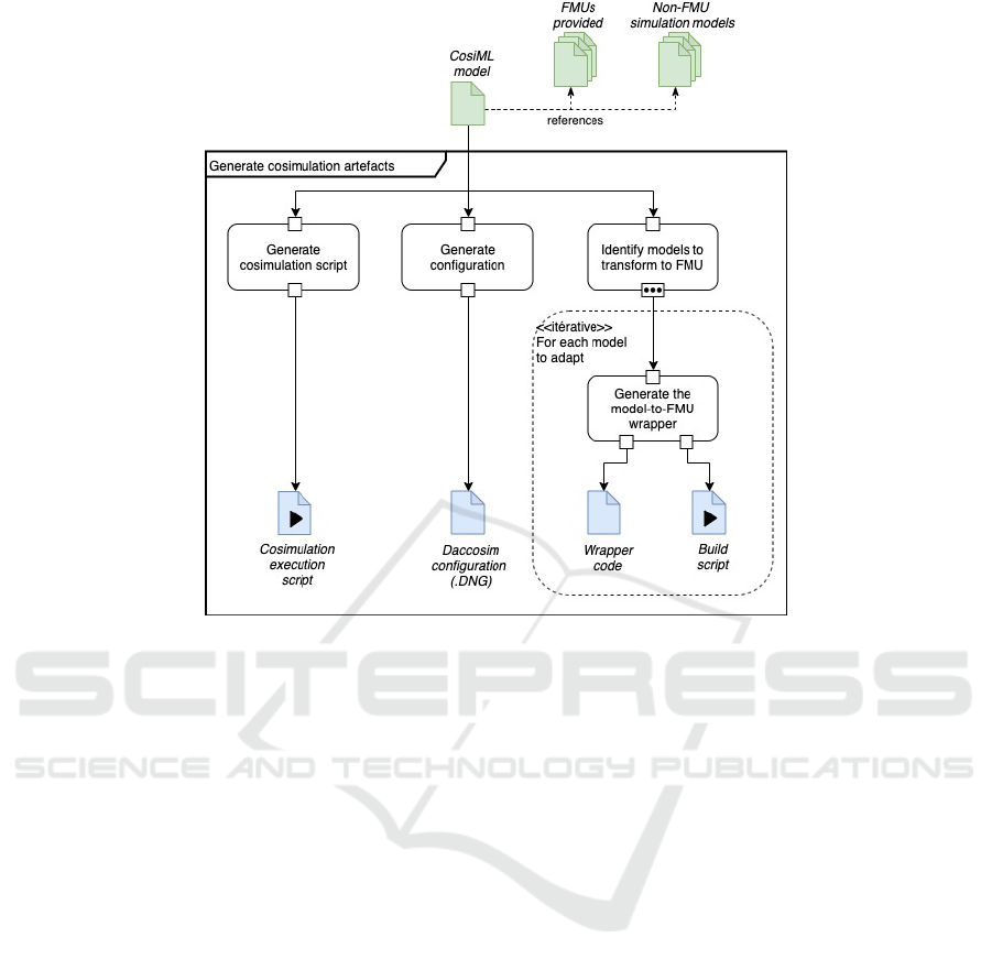
Figure 5: Generation process of the cosimulation artifacts, from a CosiML model.
grid cosimulation, and shows the integration of the
current toolchain with the usual modeling tools of the
different teams.
4.4 Download
Our toolchain is shared on a github repository at:
https://github.com/davidoudart-pro/SGridSF.
The sources of the CosiML language and gene-
ration plugins are available, as well as the necessary
files to replay the cosimulation of the use case pre-
sented in this article.
5 USE-CASE COSIMULATION
5.1 The Use-case of an Islanded Smart
Grid
We chose a real use case from the French power
utility to illustrate our contribution, and validate our
toolchain. The system is an island with a power grid
that is independent from the mainland grid, with its
own production equipments. A diesel power plant is
the main energy producer, and is complemented by
a photovoltaic farm. The main issue in the config-
uration is that the renewable energy supply is inter-
mittent. Indeed, as the photovoltaic source relies on
sunlight and needs a clear sky for its production, it
makes it as variable and unpredictable as the weather.
In order to balance the production with the consump-
tion, it has to be sometimes prevented from producing
as much as it could, which causes economic loss and
carbon footprint degradation. Therefore, a chosen so-
lution is to add a battery storage to damp the variabil-
ity of the production, with the purpose of minimizing
the limitations of the photovoltaic farm. It could even
allow the operator to shut down the diesel plant for
some period and rely only on the battery and photo-
voltaic production.
To maximize the efficiency of the system, we
need an Energy Management System (EMS) cou-
pled with a Supervisory Control And Data Acquisi-
tion (SCADA) in order to implement an intelligent
control of the production. The EMS monitors the
state of the power grid (value of the voltage at va-
rious control points, state of switches), and drives
some of its equipments (giving voltage setpoints, lim-
iting the injection of power by a source) through the
SCADA. The EMS can collect other information such
as weather and consumption forecasts from external
information systems, as well as user preferences, in
order to optimize the operation of the grid.
Before telling how the EMS controls the equip-
ments on the grid, we have to explain how the power
A Model based Toolchain for the Cosimulation of Cyber-physical Systems with FMI
21

flow is established on a power grid. Knowing the
power needed by the consumers, we can set power
production setpoints to the various sources of the grid
in order to balance the consumption. However, losses
on transmission lines can never be known, so we need
at least one equipment not power constrained, capa-
ble of producing the loss or absorb the unpredictable
excess. This equipment is generally the one having
the highest size generator. In our case it is the diesel
plant when it is connected to the grid, the battery and
its converter when it is not.
The EMS sends control signals to the various
equipment of the grid:
• photovoltaic farm: the EMS decides if the produc-
tion needs to be limited and how much;
• battery: there are two cases for this equipment.
When the diesel plant is coupled to the grid and
balances the power on the grid, the EMS con-
trols the power absorbed or injected by the battery.
When the diesel plant is shut down, the EMS does
not control the battery and lets its power converter
balance the power on the grid.
• diesel plant: the EMS decides if it is coupled to
the grid (and produces power) or not. When it is
coupled to the grid, it cannot produce less than a
minimum power, so it can happen that the photo-
voltaic farm has its production limited. To avoid
it, the diesel is turned off when the battery and
the photovoltaic production are able to cover the
consumption needs.
Because of all the different modes in which the
grid can be, depending on the weather, on the man-
agement of the charge of the battery and on the vari-
ability of the consumption, simulation is very useful
to test and validate a design of the solution, before any
deployment on the field and expensive investments.
5.2 Cosimulation Scenario
The simulation of the islanded smart grid is a good
example of a cyber-physical system involving seve-
ral knowledge fields, and several teams with different
modeling tools. We used Modelica
5
with the Dymola
software to model the grid power flow because they
are well-known tools among electrical engineers, and
they fully support the FMI standard and the export to
FMU (Elsheikh et al., 2013). The simulation unit con-
tinuously evaluates the electrical power state of the
grid according to production and consumption cons-
traints. Figure 6 shows the simplified model of the
power flow and its inputs.
5
https://www.modelica.org/, component-oriented mod-
eling language based on equations set declaration.
Figure 6: Simplified Modelica model of the islanded grid.
Some of these constraints are computed and de-
cided by the algorithm of the EMS. The EMS pro-
duces discrete event signals, reacting to the evolution
of the state of the grid. There is no conventional tool
supporting the modeling of reactive systems and also
handling FMI. Complex algorithms are usually mod-
eled with textual procedural languages such as C or
Java. There are tools supporting the export of such
models toward FMU, but they require additional ef-
forts and specific code refactoring and writing. Our
toolchain supports the automatic transformation of a
Java model into an FMU, with the generation of a
wrapper code implementing the JavaFMI Framework
library, and the use of the JavaFMI builder tool. We
developed a first, simple Java algorithm of the EMS
which takes the current state of the grid as input and
does not use forecasts. It computes controls every 15
minutes, but continuously monitors the current state
of the grid equipments in case emergency controls are
required. The Figure 7 shows an activity diagram, il-
lustrating this process. This simple model can give
reference simulation results, as a base of comparison
with more complex and complete algorithms provided
by various vendors.
These components need to be tested on multiple
scenarios. We have access to some data sets describ-
ing the consumption of the island and the weather
conditions over time at various times of the year. The
toolchain also supports the automatic transformation
of a timed-CSV file into an FMU, so we can use these
data sets in our cosimulation (via the CosiML CSVS-
cenario element).
Eventually, our CosiML cosimulation model in-
volves three simulation units:
• GridFmu which computes the electrical state of
the system
• EmsFmu which computes the controls to send to
MODELSWARD 2020 - 8th International Conference on Model-Driven Engineering and Software Development
22
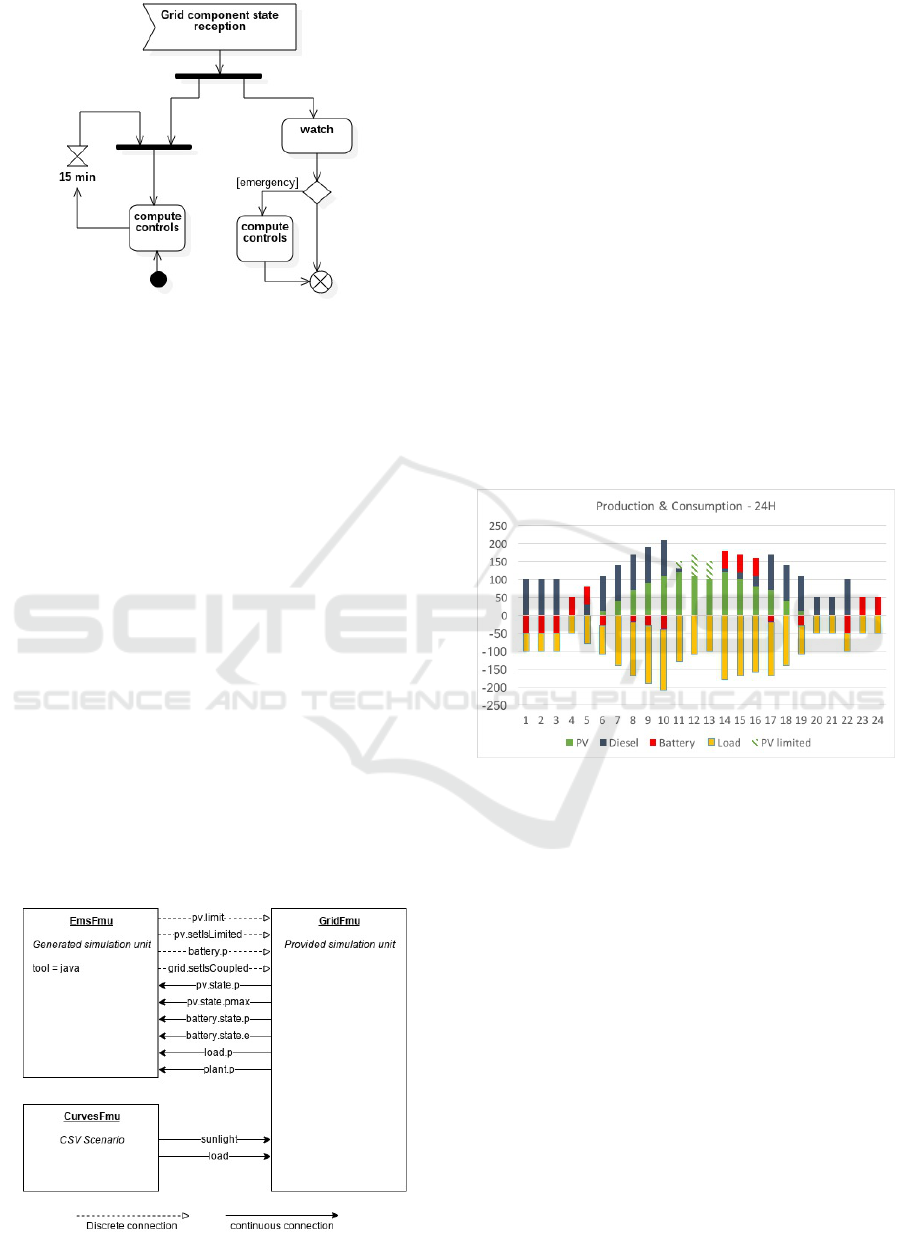
Figure 7: EMS monitoring process, with periodic and emer-
gency controls.
the grid components
• CurvesFmu which plays the consumption and
sunlight intensity evolution from the given data
sets.
The CosiML model of this cosimulation
instantiates GridFmu as a ProvidedSimulation-
Unit, because it is provided as an export from
Dymola. EmsFmu is instantiated as a Generated-
SimulationUnit because the model is provided as
java source code, and our toolchain will generate
the FMU. Finally CurvesFmu is instantiated as a
CSVScenario, because we are provided with a CSV
file that will be used to generate an FMU that plays
the data contained in the file.
As we said previously, the CosiML model has
been edited with the EMF’s Sample Reflective Ecore
Model Editor, and stored in the XMI format. Figure 8
illustrates the XMI CosiML model’s content by ex-
pliciting the connections between the three FMUs and
their variability (solid lines for continuous signals,
dotted lines for discrete events).
Figure 8: Connections between the FMUs of the use case.
5.3 Simulation and Decisions
The use case presents two main concerns: 1) how to
optimize the battery characteristics in order to imple-
ment an efficient management of the production and
keep investment as low as possible? And 2) how to
test the efficiency of the chosen EMS algorithm?
From the CosiML model, the toolchain generates
the necessary wrapper files to build the EmsFmu and
CurvesFmu FMUs, as well as the DACCOSIM mo-
del of the cosimulation. In addition, a script is gen-
erated to create automatically the missing FMUs, and
to launch the DACCOSIM cosimulation.
In our case, the cosimulation evaluates the behav-
ior of the grid on a full day (24 hours). Figure 9
shows the average and cumulated per-hour production
(over the x-axis) and consumption (below the x-axis)
of each equipment on the day, for particular load and
photovoltaic maximal production curves (and initial
conditions).
Figure 9: Consumption and production of electricity over a
full day.
The energy balance has been ensured all day (no
black-outs) meaning our design solution is effective
on this particular scenario. However, between 11am
and 2pm, the photovoltaic production has been lim-
ited (see hatched bars). Looking at the results (not
shown in the figure), we see that the charge of the bat-
tery was already maximal and could not absorb the
extra production. There is consequently a potential
for optimization of our solution. Increasing the ca-
pacity of the battery, or improving the algorithm of
the EMS are two possible iterations. Once the models
are updated, the execution of the toolchain automati-
cally updates the simulation artifacts and executes the
cosimulation again.
A Model based Toolchain for the Cosimulation of Cyber-physical Systems with FMI
23

6 OBSERVATIONS
The key motivation behind our work is to reduce the
cost of iterations in the design of systems by automat-
ing the cosimulation of the models using a model-
driven approach. To be useful in an industrial context,
we need to fulfill the following requirements: each it-
erative step of the process must provide a quick feed-
back; the upfront modeling cost must be recovered in
the following phases of analysis, maintenance, etc.;
business experts must concentrate on their core skills.
We presented in this paper a toolchain based on
a cosimulation DSL to reference simulation models
and characterize some coupling constraints between
them. The various generators allow the generation
of simulation units and deployment scripts from this
cosimulation model. Hence, this automated process
provides the possibility to make changes to the cosi-
mulation scenario with minimal efforts. We illustrate
this through the following industrial scenarios.
In a first scenario, a functional architect has to
compare components from various vendors, for ex-
ample to find the best EMS solution (EMSGrid in our
previous use case). To guarantee the correct integra-
tion of the simulation model provided by the vendor,
the tender documents include requirements deduced
from the CosiML model. The selection of the right
component is simplified because:
• Using the tool chain, the architect can quickly
build a test environment, by providing input data
inside a CSV file, automatically generating a new
FMU and a cosimulation model, then testing mul-
tiple configurations easily.
• To select the components to be used in the co-
simulation, only the pathFMU attribute of the
ProvidedSimulationUnit must be modified and the
new cosimulation set up can be generated.
In a second scenario, we want to involve elec-
trotechnical engineers to build a load flow model of
the power grid (GridFMI in our previous use case).
This is possible without an intensive training because
they can use their own specific tools to build the simu-
lation model (Dymola, PowerFactory, etc.), and there
are only few basic concepts (input, output, discrete
or continuous variability) to be explained in order to
build the CosiML model. Once they develop a mo-
del conforming to the CosiML metamodel, they can
then use an iterative approach to improve the model
without involving other collaborators, thanks to our
toolchain, which automatically integrates their work
to the cosimulation platform.
Finally, in a third scenario, we consider the case
of a modification of one simulation model inducing
a modification of the CosiML model, and especially
among the coupling constraints between models (e.g.
adding or renaming several ports).Firstly, the valida-
tion rules of our toolchain guarantee the consistency
of the CosiML model. Secondly, the automated ex-
ecution process of the cosimulation will raise errors
until each impacted simulation model makes the ne-
cessary adjustments. Thirdly and finally, the imple-
mentation of the adjustments might be partially done
by the generators of the toolchain.
7 CONCLUSION AND
PERSPECTIVES
By automating some verifications and the generation
of cosimulation artifacts, model driven approaches al-
low shorter, less costly and less error prone iterations
on a solution design. Our toolchain relies on an ab-
stract CosiML model of the system to check the con-
sistency of the different simulation units, to generate
adapters for discrete event signals that cannot be used
as is in an FMI simulation, and to generate FMUs
from models developed with different tools. It uses
the FMI standard and benefits from its many advan-
tages regarding CPS simulation in industry. It can also
integrate FMUs exported by some modeling tools in
the cosimulation, allowing models from different sys-
tem domains to be developed with the relevant tools,
by experimented teams, while protecting industrial
property inside FMUs.
The CosiML language and its generators have
been used on a real industrial case, which involves
both continuous and discrete signal exchanges. We
recently managed to integrate an FMU built from an
OMNeT model of a communication network in a co-
simulation, which will allow us to run finer simula-
tions of a smart grid that take into account the perfor-
mance and limitations of the communication network.
CosiML and our tool chain have been designed to sup-
port new modeling tools and new generators, and the
integration of models from OMNeT in the tool chain
will be an opportunity to check this. The modular
nature of the different transformations also helps to
adapt the generated artifacts to different versions of
FMI. For instance, the support for a more precise de-
tection of discontinuities in FMI v2.1 may lead to a
new adapter for discrete event signals, while keeping
the current one for cosimulations using older versions
of FMI.
Finally, we want to bring a better integration with
the design process of a system using simulation. In-
deed, we are aware that developing a CosiML model
implies a previous analysis phase, to identify which
kind of simulation models need to be developed, and
MODELSWARD 2020 - 8th International Conference on Model-Driven Engineering and Software Development
24

for which purpose. We propose to use another lan-
guage to represent the system functions to simulate,
independently of their implementation models, and to
build a model transformation toward CosiML.
REFERENCES
Andr
´
en, F., Strasser, T., and Kastner, W. (2017). Engineer-
ing Smart Grids: Applying Model-Driven Develop-
ment from Use Case Design to Deployment. Energies,
10(3):374.
Blochwitz, T., Otter, M., Arnold, M., Bausch, C., Elmqvist,
H., et al. (2011). The functional mockup interface for
tool independent exchange of simulation models. In
Proceedings of the 8th International Modelica Con-
ference, pages 105–114.
Broman, D., Greenberg, L., Lee, E. A., Masin, M., Tripakis,
S., and Wetter, M. (2015). Requirements for Hybrid
Cosimulation Standards. In Proceedings of the 18th
International Conference on Hybrid Systems: Compu-
tation and Control, HSCC ’15, pages 179–188. ACM.
Cremona, F., Lohstroh, M., Broman, D., Lee, E. A., Masin,
M., and Tripakis, S. (2019). Hybrid co-simulation:
it’s about time. Software and System Modeling,
18(3):1655–1679.
Dahmann, J. S. and Morse, K. L. (1998). High Level Ar-
chitecture for simulation: An update. In Proceed-
ings. 2nd International Workshop on Distributed In-
teractive Simulation and Real-Time Applications (Cat.
No.98EX191), pages 32–40.
Elsheikh, A., Awais, M. U., Widl, E., and Palensky, P.
(2013). Modelica-enabled rapid prototyping of cyber-
physical energy systems via the functional mockup in-
terface. pages 1–6. IEEE.
´
Evora G
´
omez, J., Hern
´
andez Cabrera, J. J., Tavella,
J.-P., Vialle, S., Kremers, E., and Frayssinet, L.
(2019). Daccosim NG: Co-simulation made simpler
and faster. In The 13th International Modelica Con-
ference, pages 785–794.
Gomes, C., Meyers, B., Denil, J., Thule, C., Lausdahl, K.,
Vangheluwe, H., and De Meulenaere, P. (2018a). Se-
mantic adaptation for FMI co-simulation with hierar-
chical simulators. SIMULATION.
Gomes, C., Thule, C., Larsen, P. G., and Vangheluwe, H.
(2018b). Co-Simulation: A Survey. ACM Computing
Surveys, 51(3):49:1–49:33.
Guermazi, S., Tatibouet, J., Cuccuru, A., Dhouib, S.,
G
´
erard, S., and Seidewitz, E. (2015). Executable mod-
eling with fUML and alf in papyrus: Tooling and ex-
periments. In EXE@MoDELS.
Li, W., Monti, A., Luo, M., and Dougal, R. A. (2011). VP-
NET: A co-simulation framework for analyzing com-
munication channel effects on power systems. In 2011
IEEE Electric Ship Technologies Symposium, pages
143–149.
Muller, S. C., Georg, H., Nutaro, J. J., Widl, E., Deng, Y.,
Palensky, P., Awais, M. U., and al. (2018). Interfacing
Power System and ICT Simulators: Challenges, State-
of-the-Art, and Case Studies. IEEE Trans. Smart Grid,
9(1):14–24.
Nutaro, J. (2011). Designing power system simulators
for the smart grid: Combining controls, communi-
cations, and electro-mechanical dynamics. In 2011
IEEE Power and Energy Society General Meeting,
pages 1–5.
Oudart, D., Cantenot, J., Boulanger, F., and Chabridon, S.
(2019). An Approach to Design Smart Grids and Their
IT System by Cosimulation:. In MODELSWARD 19,
pages 370–377. SCITEPRESS - Science and Technol-
ogy Publications.
Palensky, P., Van Der Meer, A. A., Lopez, C. D., Joseph, A.,
and Pan, K. (2017). Cosimulation of Intelligent Power
Systems: Fundamentals, Software Architecture, Nu-
merics, and Coupling. IEEE Industrial Electronics
Magazine, 11(1):34–50.
Paris, T., Ciarletta, L., and Chevrier, V. (2017). Design-
ing co-simulation with multi-agent tools: a case study
with NetLogo. In Francesco Belardinelli, E. A., ed-
itor, 15th European Conference on Multi-Agent Sys-
tems (EUMAS 2017), volume 10767 of Multi-Agent
Systems and Agreement Technologies, pages 253–267,
´
Evry, France. Springer.
Rohjans, S., Lehnhoff, S., Sch
¨
utte, S., Andr
´
en, F., and
Strasser, T. (2014). Requirements for Smart Grid sim-
ulation tools. In 2014 IEEE 23rd International Sym-
posium on Industrial Electronics (ISIE), pages 1730–
1736.
Suri, K., Cuccuru, A., Cadavid, J., Gerard, S., Gaaloul, W.,
and Tata, S. (2017). Model-based Development of
Modular Complex Systems for Accomplishing Sys-
tem Integration for Industry 4.0. In Proceedings of the
5th International Conference on Model-Driven Engi-
neering and Software Development - Volume 1: MOD-
ELSWARD,, pages 487–495. ScitePress.
Tavella, J.-P., Caujolle, M., Vialle, S., and al. (2016). To-
ward an Accurate and Fast Hybrid Multi-Simulation
with the FMI-CS Standard. In Emerging Technologies
and Factory Automation (ETFA-2016), Berlin, Ger-
many.
Van Acker, B., Denil, J., Vangheluwe, H., and De Meule-
naere, P. (2015). Generation of an optimised master
algorithm for fmi co-simulation. In DEVS Integrative
M&S Symposium, DEVS ’15. Society for Computer
Simulation International.
Yang, C.-H., Zhabelova, G., Yang, C.-W., and Vyatkin, V.
(2013). Cosimulation Environment for Event-Driven
Distributed Controls of Smart Grid. IEEE Trans. In-
dustrial Informatics, 9(3):1423–1435.
Zhao, H., Apvrille, L., and Mallet, F. (2017). Multi-View
Design for Cyber-Physical Systems. In PhD Sympo-
sium at 13th International Conference on ICT in Ed-
ucation, Research, and Industrial Applications, pages
22–28, Kiev, Ukraine.
A Model based Toolchain for the Cosimulation of Cyber-physical Systems with FMI
25
