
Using Local Refinements on 360 Stitching from Dual-fisheye Cameras
Rafael Roberto
1
, Daniel Perazzo
1
, Jo
˜
ao Paulo Lima
1,2
, Veronica Teichrieb
1
,
Jonysberg Peixoto Quintino
3
, Fabio Q. B. da Silva
4
, Andre L. M. Santos
4
and Helder Pinho
5
1
Voxar Labs, Centro de Inform
´
atica, Universidade Federal de Pernambuco, Recife/PE, Brazil
2
Departamento de Computac¸
˜
ao, Universidade Federal Rural de Pernambuco, Recife/PE, Brazil
3
Projeto de P&D CIn/Samsung, Universidade Federal de Pernambuco, Recife/PE, Brazil
4
Centro de Inform
´
atica, Universidade Federal de Pernambuco, Recife/PE, Brazil
5
SiDi, Campinas/SP, Brazil
Keywords:
Stitching 360, Dual-fish Eye Camera, Panoramic Image.
Abstract:
Full panoramic images have several applications, ranging from virtual reality to 360
◦
broadcasting. Such
visualization method is growing, especially after the popularization of dual-fisheye cameras, which are
compact and easy-to-use 360
◦
imaging devices, and low-cost platforms that allow immersive experiences.
However, low-quality registration and compositing in which artifacts are noticeable in the stitching area can
harm the user experience. Although it is challenging to compose such images due to their narrow overlap area,
recent works can provide good results when performing a global alignment. Nevertheless, they often cause
artifacts since global alignment is not able to address every aspect of an image. In this work, we present a
stitching method that performs local refinements to improve the registration and compositing quality of 360
◦
images and videos. It builds on a feature clustering approach for global alignment. The proposed technique
applies seam estimation and rigid moving least squares to remove undesired artifacts locally. Finally, we
evaluate both to select the best result between them using a seam evaluation metric. Experiments showed that
our method reduced the stitching error in at least 42.56% for images and 49.45% for videos when compared
with existing techniques. Moreover, it provided the best results in all tested images and in 94.52% of the video
frames.
1 INTRODUCTION
Several applications widely use panoramic images.
For instance, Facebook developed a extension for
360
◦
photos to their News Feed service while
applications like Google Expeditions use 360
◦
panoramas to create an immersive experience for
Virtual Reality that transports students to places they
can not visit, such as the bottom of an ocean or the
Moon surface. Moreover, news outlets such as the
New York Times are using 360
◦
movies to report on
major events, such as the war on Syria (Times, 2016).
Most of these panoramic images are created
using a set of cameras that can take pictures in
every direction. This arrangement of cameras can
capture the entire surroundings to produce 360
◦
images efficiently. However, this setup is expensive
and not much portable. In contrast, dual-fisheye
cameras are small, lightweight, cheap, and able to
capture high-quality panoramic images. However,
the stitching process for images captured with
dual-fisheye cameras is more difficult because the
images have a narrow intersection area. In fact,
methods designed for regular images are not able to
stitch dual-fisheye captures with good quality.
In this paper, we propose a stitching technique
that can perform local refinements in order to improve
the quality of the global alignment. Our method uses
feature clusters to perform global alignment.Then, we
apply two local refinements: the first one based on
rigid moving least squares (RMLS) transformation
and the second one based on seam estimation. We
evaluate them using a seam error metric to find which
one provides the best result. Our method can be
used to stitch both images and videos. The main
contributions of our paper are:
1. A stitching method for dual-fisheye lens cameras
that makes local refinements to improve output
quality (Section 3);
Roberto, R., Perazzo, D., Lima, J., Teichrieb, V., Quintino, J., B. da Silva, F., Santos, A. and Pinho, H.
Using Local Refinements on 360 Stitching from Dual-fisheye Cameras.
DOI: 10.5220/0008874100170026
In Proceedings of the 15th International Joint Conference on Computer Vision, Imaging and Computer Graphics Theory and Applications (VISIGRAPP 2020) - Volume 5: VISAPP, pages
17-26
ISBN: 978-989-758-402-2; ISSN: 2184-4321
Copyright
c
2022 by SCITEPRESS – Science and Technology Publications, Lda. All rights reserved
17

2. An adaptation of this approach to use these local
refinements to stitch videos (Section 4);
3. Quantitative evaluation for both image and video
stitching using different cameras. (Section 5).
2 RELATED WORK
In the field of computer vision, one of the oldest
types of algorithms is image alignment and stitching
methods (Szeliski, 2006). It is possible to create
panoramas using these types of algorithms. Several
techniques and methods have already been developed
for tackling this problem (Szeliski, 2006). (Brown
and Lowe, 2007) proposed a technique to build
panoramic images based on invariant features and
homography warping. (Jia and Tang, 2008), on
the other hand, used a structure deformation method
based on 1D features.
Moreover, the advent of dual-fisheye cameras
enabled a new method for the creation of 360
◦
panoramas and it is gaining a noticeable adoption,
as evidenced by applications using such cameras
that range from surveillance (Al-Harasis and
Sababha, 2019) to visual feedback for telepresence
robots (Dong et al., 2019). This also includes the
generation of panoramas through fisheye cameras
mounted on drones (Zia et al., 2019) and a series
of 360
◦
journalistic videos made by the New York
Times (Times, 2017). However, in this particular type
of stitching, challenges arise due to the distortion
caused by the fisheye lenses and, in the particular
case of dual-fisheye images, the limited region of
overlap.
In fisheye image stitching, most methods include
three stages: fisheye image unwarping, image
alignment, and image blending. An example is the
work of (Ho and Budagavi, 2017), who developed
a method to stitch dual-fisheye images. In the
unwarping step, they perform an equirectangular
projection of each fisheye image. Differently from
our work, the alignment step uses an affine warp
based on a precomputed calibration procedure. In the
final step, a ramp function is applied to generate a
seamless blend. In a following paper, they adopt a
similar approach, but, instead of an affine warp, they
used a RMLS deformation to align the points in a
local manner (Ho et al., 2017). As in their previous
work, the alignment is precomputed in an offline
calibration phase to determine how the deformation
will take place. However, in configurations too
different from the setup used to calibrate the control
points and target points, it is noticeable the creation
of artifacts.
In another work, (Souza et al., 2018) uses clusters
of image features to estimate a homography that
aligns the images. In (Lo et al., 2018), the alignment
step is computed by a local mesh warping based on
features extracted from the image, which does not
require a calibration stage. Also, the blending step is
performed using seam cuts and multi-band blending.
The common thing about these two studies is that
they only perform global alignment to compose the
panoramic image, while our work also applies local
refinements to it.
Regarding the refinement of the stitched image,
various approaches were developed. In (Dhiman
et al., 2018), a method is proposed to minimize
ghosting and brightness artifacts in 360
◦
High
Dynamic Range (HDR) images. Along with this,
numerous dual-fisheye camera calibration methods
were developed, such as those presented in (Gao and
Shen, 2017) and (Aghayari et al., 2017).
After the stitching has been done, it is important
to have a way to assess the quality of the final
panorama. In (Azzari et al., 2008), a methodology
and a synthetic dataset, with a reference panorama,
are proposed to allow a quantitative evaluation of
image stitching algorithms based on the mean squared
error (MSE) metric. Meanwhile, (Ghosh et al.,
2012) robustly apply several metrics, some that use
a previous panorama ground truth and some that do
not. The main idea is to quantitatively assess some
aspects of the stitched image, such as image blending
quality and image registration quality. Furthermore,
in (Dissanayake et al., 2015), a quantitative method
to assess the quality of stitched images is presented
that does not use a reference ground truth. Moreover,
the research utilized a qualitative approach based on
surveys and the ranking of the images to provide
an alternative metric and to validate the quantitative
methods thus presented.
3 IMAGE STITCHING
Similar to (Souza et al., 2018), our method uses
local invariant features and template matching to
perform global alignment of dual-fisheye images. The
main difference is the addition of local refinements
to improve the stitching quality in three steps.
Figure 1 illustrates the flow of our method. First,
we use graph cut to perform an seam estimation
of the stitching seam (Kwatra et al., 2003). Then
we employ RMLS to apply a local transformation
around misaligned features (Schaefer et al., 2006).
Thereafter, we evaluate each of the improvements
to check if it resulted in a better stitched image to
VISAPP 2020 - 15th International Conference on Computer Vision Theory and Applications
18
select accordingly (Gao et al., 2013). Additionally,
we adapted that approach for videos and used the
temporal factor to avoid jittering and to improve
execution time.
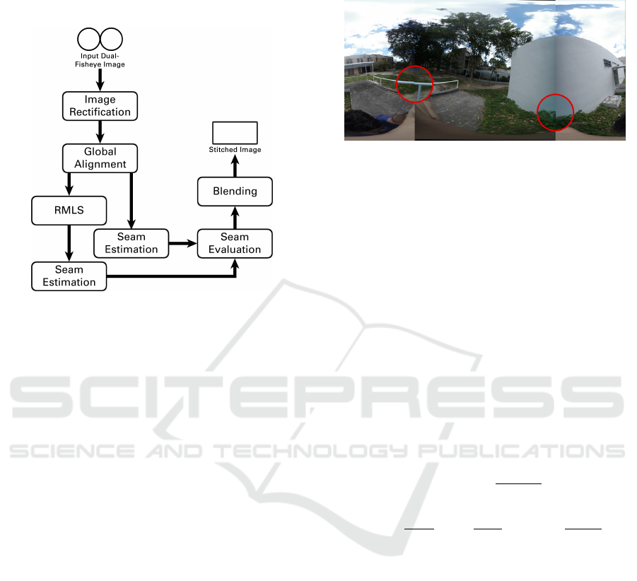
Figure 1: Execution flow of our stitching method for
images.
At first, we perform Image Rectification, which
takes the original dual-fisheye image and rectifies it
into two equirectangular projections, one for each
lens (Bourke, 2016). These images are I
b
and I
c
,
which have the content in the border and the center
of the output stitched image, respectively. It is not
necessary to perform color adjustment in the images
because the camera compensate the illumination
difference between both lenses. Moreover, in our
tests, the results worsen when we applied such
corrections. Then, for the Global Alignment step,
we extract local invariant features from those rectified
images to create textured clusters. We use them in a
template matching step in order to compute the global
homography that will transform I
c
into I
0
c
, which
will be aligned with I
b
(Souza et al., 2018). The
remaining steps of our approach are responsible for
local refinements. We detail them in the following
subsections.
3.1 Rigid Moving Least Squares
Overall, global alignment provides a good result when
registering most of the images. However, sometimes,
it results in artifacts because the global homography
transformation is not able to fully describe the 3D
alignment between the lenses, as seen in Figure 2.
One possible solution to eliminate these artifacts is
to apply local refinements only around them in order
to not compromise the global transformation. In this
sense, we employ RMLS (Schaefer et al., 2006) to
transform the images aiming to refine the final result
locally.
Figure 2: Although the global alignment is adequate in
most of the image, it is possible to note artifacts on specific
regions (red circles).
RMLS is a type of deformation that, given two
sets of matching points C (control points) and T
(target points), all points c
i
∈ C are moved to
the location of their corresponding points t
i
∈ T.
Additionally, the image around the control points
is warped accordingly in a rigid-as-possible manner.
The main advantage of this type of transformation is
due to its local nature since it ensures that areas far
from the primary deformation zone remain practically
unaffected.
To apply this transformation, we need to calculate
the RMLS warping function f (v), that will indicate
the resulting position in the final image for every point
v
i
in the original one (Schaefer et al., 2006), which is
defined as
f (v) =
k
v − c
∗
k
2
~
f (v)
~
f (v)
2
+ t
∗
, (1)
where c
∗
=
∑
i
w
i
c
i
∑
w
i
, t
∗
=
∑
i
w
i
t
i
∑
w
i
and w
i
=
1
|c
i
−v|
2α
. The
~
f (v) function is described as
~
f (v) =
∑
(t
i
− t
∗
)A
i
(2)
and A
i
is the following matrix:
A
i
= w
i
c
i
− c
∗
φ(c
i
− c
∗
)
v − c
∗
φ(v − c
∗
)
T
, (3)
where φ(p) is a operator that, given a 2D point p(x,y),
φ(p) = (y,−x).
This function requires a deformation force α and
the points c
i
and t
i
. A value α = 0.0 means that RMLS
will not locally warp the images. As it increases, the
function will extend the area of deformation around
each point. In our case, the corresponding points
c
i
and t
i
are the invariant features extracted during
global alignment, with α experimentally set to 1.0.
After applying this function to all points v
i
, we locally
Using Local Refinements on 360 Stitching from Dual-fisheye Cameras
19

deform the image around corresponding features to
minimize artifacts in the final image.
3.2 Seam Estimation
Another local refinement aims to find which pixels
to use from both overlap areas. For that, we
used an image texture synthesis technique (Kwatra
et al., 2003). Here, image segments are defined
as patches, which are merged into one image in a
process called patch fitting. It is a graph-cut approach
for texture synthesis that results in an image quilt.
Given multiple patches with overlapping regions,
we estimate the specific area of each patch that is
transferred to the final output texture. This area is
called a seam, and this estimation is called Seam
Estimation. In other words, considering the merging
of two overlap images, the seam is the region from
each image that minimizes artifacts after the merge.
However, when dealing with multiple images, it is
necessary to estimate the correct placement of a patch
based on the overlapping information with the ones
already in the output texture.
In order to apply the seam estimation, we need to
define which patches to merge, the offset values, and
the output texture. There are two overlapping regions
between the two aligned images I
b
and I
0
c
, called
O
l
and O
r
, representing the left and right regions
respectively. We define these regions as patches
since they will be merged in the final 360
◦
panorama.
This resulting panorama will be the output texture.
Regarding the offset of these two patches, we know
that the position of O
l
and O
r
are around 25% and
75% of the image width, respectively.
After the definition of these terms, we use a
graph-cut approach that uses the quality measure
of transition. This measure is based on the color
difference between pairs of pixels using the cost
functions M
l
and M
r
, defined as
M
l
=
O
b
l
(s) − O
c
l
(s)
2
+
O
b
l
(t) − O
c
l
(t)
2
, (4)
M
r
=
O
b
r
(s) − O
c
r
(s)
2
+
O
b
r
(t) − O
c
r
(t)
2
, (5)
where s and t are two adjacent pixel positions in the
overlap region, O
b
l,r
(s) denotes the pixel colors at
position s of the left and right overlapping regions
of the border equirectangular projection and O
c
l,r
(s)
denotes the same for the center equirectangular
projection.
These cost functions M
l
and M
r
can be described
as the disparity between adjacent pixels in the left and
right overlapping regions. To minimize the disparity
means minimizing the cost functions of these regions.
Thus, we search for a minimum cut based on
graph-flow, which results in the paths P
l
and P
r
for the
left and right overlapping region, respectively. They
contain the best point where the transition between
the two equirectangular projections must happen, as
shown in Figure 3.
Figure 3: The estimated cutting paths are shown in green.
3.3 Seam Evaluation
Nevertheless, sometimes the RMLS deformation
results in the creation of artifacts in the panorama
image due to incorrect matches. Therefore, we
compare the 360
◦
panoramas with and without
applying RMLS to select the best result in a process
called Seam Evaluation. This measurement assesses
the quality of these images based on the similarity of
the stitching region concerning I
b
and I
0
c
(Gao et al.,
2013).
Aiming to evaluate the images with RMLS (I
rmls
)
and without it (I
seam
), we traverse through both
stitching paths in order to grade them, as illustrated
in Figure 4. First, we get a patch centered at every
pixel v
i
on P
l
and P
r
of I
rmls
. Then, we compute its
cross-correlation with a patch centered in the same
position v
i
on I
b
and I
0
c
on the RGB color space.
The error E
rmls
is the average of all cross-correlation
values computed on both cutting paths. It grows as
the patches become dissimilar, decreases for alike
patches and, potentially, turns to 0 if the patches are
identical. We use the same process to compute E
seam
on I
seam
. Finally, we select between I
rmls
and I
seam
the one that has the smallest error.
3.4 Blending
Although we apply global transformations and local
refinements, the transition in the stitching path can
still be noticeable for the end user. That happens
because humans are very good at identifying abrupt
VISAPP 2020 - 15th International Conference on Computer Vision Theory and Applications
20
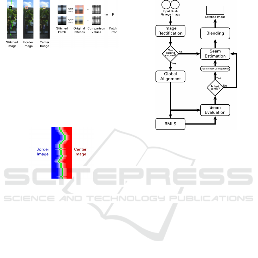
Figure 4: Seam evaluation process.
changes. Therefore, we apply a ramp function
to achieve smooth transitions between both images.
However, instead of applying this function in the
entire overlap area as in existing works (Ho and
Budagavi, 2017; Souza et al., 2018), we use the
stitching path to guide the ramp function. As shown in
Figure 5, we create transitions for every row in both
stitching paths P
l
and P
r
, which are centered at the
points in the stitching path.
Figure 5: Ramp function centered in the stitching cut.
Thus, for every pixel v
i
on P
l
and P
r
, we define
the ramp function as
R
l
(v
i
) = (1 − β) ∗ I
b
+ β ∗ I
c
,
R
r
(v
i
) = (1 − β) ∗ I
c
+ β ∗ I
b
,
(6)
where, for a horizontal window size w centered in v
i
,
β is
β =
x + w/2
w
. (7)
4 VIDEO STITCHING
A video can be defined as a sequence of images
and we could apply our stitching method on each
individual frame. However, this is not pleasant
for the users because our local refinements may
cause jitter. Moreover, this approach is not efficient
because the alignment between both fisheye images
does not change so often during the video and
it is not necessary to compute it on every frame.
Therefore, we adapted our method to deal with this
characteristic, as can be seen in Figure 6.
Figure 6: Execution flow of our stitching method for videos.
At the Global Alignment step, we calculate
the global homography using the same process
mentioned in Section 3. The difference is that we
only compute it once at every second. However,
this transformation may not be the best one due to
the quality of the invariant features extracted in the
current image. This will have an impact on both
global alignment and RMLS deformation.
To address this, we use Seam Evaluation for two
purposes in the video pipeline. First, to determine if
we are going to use RMLS or not when computing
the new alignment configuration. And, after that, to
verify if the current configuration is better than the
best one available until this moment. Finally, we
use the best alignment configuration to perform Seam
Estimation and Blending. We repeat this process after
one second. Until then, we use the best alignment
configuration available in the intermediate frames.
4.1 Temporal Coherence
To reduce jitter when changing the alignment
configuration, we interpolate between them. These
configurations are composed by a global homography
H and in some cases, a warping function f (v).
Regarding the homography, we create intermediate
points in order to have a smooth transition between
H
prev
and H
best
(Souza et al., 2018).
Concerning the transition of the RMLS
function, we use the constant α that indicates
the transformation strength. We have the control
and target points C
prev
and T
prev
. We linearly
Using Local Refinements on 360 Stitching from Dual-fisheye Cameras
21
decrease α until it reaches 0.0 to eliminate all RMLS
deformation using this set of points from the previous
configuration. At this moment, the image has no local
deformation using RMLS. After that, we increase α
on the RMLS of the best configuration from 0.0 to
1.0 and we incrementally add RMLS deformation
using C
best
and T
best
. This transition of α takes the
same time as the homography interpolation.
5 EVALUATION
In order to evaluate our approach, we compared
it with (Ho et al., 2017) ([Ho17]) and (Souza
et al., 2018) ([Souza18]) regarding seam error and
execution time. For that, we implemented our method
and [Souza18] in C++ using OpenCV
1
, and we used
the code provided by the authors for [Ho17]
2
. We
used a set of 97 images and 8 videos captured using
the Samsung Gear 360 under different scenarios. 49
images and 4 videos were captured with the C200
model, while 48 images and 4 videos were acquired
with the R210 model. The machine we used to
perform these tests runs with a Core i7 2.7GHz and
16GB of RAM. Regarding [Ho17] implementation,
the authors only provided the configuration data for
the C200 model using an input image size of 3840
x 1920 pixels. Thus, we used that image size in
our evaluation and we compared all three techniques
using only the C200 images and videos. As for the
R210 data, we used it to compare our method and
[Souza18].
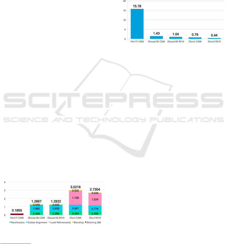
From Figure 7, it is possible to see that our method
is approximately 2.2 times slower than [Souza18].
The difference is the local refinements we apply and
they do not. When compared with [Ho17], our
method is more than 16 times slower. This can be
explained by the fact that they precompute all the
transformations in an offline step and only apply them
during execution time.
Figure 7: Image stitching average execution time (in
seconds) per image using the three methods with two
different dual-fisheye camera models.
1
Available at: http://opencv.org/
2
Available at: https://github.com/drNoob13/
fisheyeStitcher
Existing works only performs subjective
evaluations in which they visually inspect images to
assess the stitching. In this sense, we used the Seam
Evaluation error metric described in Subsection 3.3
to quantitatively indicate the stitching quality. For
each method, the assessment base is its respective
cutting path. Figure 8 shows that our method average
error is approximately 2.1 and 20 times smaller than
[Souza18] and [Ho17], respectively.
Figure 8: Image stitching average seam evaluation error
using the three methods with two different dual-fisheye
camera models.
When compared with [Souza18], it is possible
to see that the main improvement of our method
is the local refinements, which can remove most
of the artifacts left by the global alignment. Our
method has a lower error on every one of the 97
images. The image with the lowest error, shown
in Figure 9 (a), is the same for both approaches:
0.02 and 0.04 using our method and [Souza18],
respectively. Here, we have several textured regions
and objects that are distant from the camera lenses,
which benefits our invariant feature-based method.
The lowest error using [Ho17], on the other hand,
is with different images, which can be seen in
Figure 9 (b). The error was 11.66, which is very
high when compared with the other methods. One
noticeable characteristic is that the panorama image
generated using [Ho17] has a strong ghosting effect
in the overlap area. However, since they perform
calibration using chessboard patterns that are 2 meters
away from the camera (Ho et al., 2017), objects
that are around that distance seem to be sharper.
Figure 14 shows some panorama images created with
our method.
Our method and [Souza18] also share the image
with the highest error, which is shown in Figure 10 (a)
and has an error of 6.96 and 7.30, respectively. In
contrast to the best case, most of the images with
a high error, such as this one, have objects close
to the camera. This situation is challenging due to
the parallax, which is hard for the global alignment
to tackle. This influences the local refinements
because it is more effective when dealing with small
adjustments. Even considering these challenges, the
local refinements used in our method were able to
VISAPP 2020 - 15th International Conference on Computer Vision Theory and Applications
22
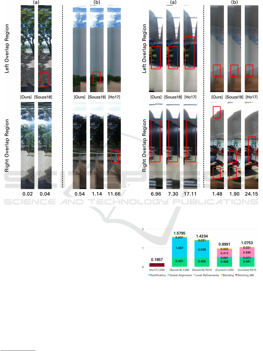
Figure 9: Overlap region of two images highlighting the
difference of each method with their respective errors below
each of them. Image (a) was acquired with the R210 camera
model and image (b) was taken using the C200 camera
model.
improve the results. [Ho17] presented the highest
error in every case. The highest error was 24.15 with
the images that can be seen in Figure 10 (b).
Regarding videos, Figure 11 shows that our
method is approximately 1.5 times faster than
[Souza18]. This happens because our method jumps
a few steps for some frames, which decreases the
average. Comparing with [Ho17], our method is
around 5.4 times slower. Even without computing
the alignment on every frame, our method is not
faster than precomputing all the transformations
beforehand.
Looking at the average Seam Evaluation error,
the value of our method is 2.09 times smaller than
[Souza18]. When comparing with [Ho17], our
method average error is 50 times smaller, which
doubles the improvement reported on images
3
. Our
3
A result video can be found at https://youtu.be/
FpXHcm4xyCs
Figure 10: Overlap region of two images highlighting the
difference of each method with their respective errors below
each of them. Both images were taken using the C200
camera model.
Figure 11: Video stitching average execution time (in
seconds) per frame using the three methods with two
different dual-fisheye camera models.
method and [Souza18] obtained better results in the
videos captured with the C200 model. That happened
because these videos are similar, most of the objects
are distant from the camera and in all of them the
camera is not moving.However, the error with [Ho17]
was 11.2% higher when compared with the image
stitching evaluation. The reason is that most of the
objects are farther than the calibration distance.
As can be expected, our method has problems
Using Local Refinements on 360 Stitching from Dual-fisheye Cameras
23
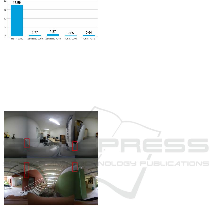
Figure 12: Video stitching average seam evaluation error
using the three methods with two dual-fisheye camera
models.
dealing with images that have low textured areas
in the overlap region. This characteristic reduces
the number of reliable features, which compromises
the quality of both global alignment and RMLS.
Figure 13 shows two challenging cases in which the
lack of features resulted in bad panoramas. Our
approach has another issue concerning black regions
that appear in some cases when global alignment
distorts a lot of the central image.
Figure 13: Most of the failure cases of our method happens
on images with low textured areas in the overlap region.
6 CONCLUSIONS
In this work, we presented a 360 stitching method for
dual-fisheye cameras that combines global alignment
with local refinements. We use local invariant
features to create textured clusters and compute the
homography that will align the images captured with
both lenses. After that, we apply RMLS to locally
transform the images aiming to remove artifacts that
are still present after the global alignment. Then,
we employ a graph-cut approach to find the optimal
seam between both overlap areas. Finally, we use
an error metric to determine what are the local
refinements that produce the best panorama. In our
evaluation, we showed that the proposed method
has good results when compared with state-of-the-art
approaches. However, it compromises the execution
time. Also, we extended this approach to video
stitching.
For future works, we plan to investigate the
use of precomputed alignment configurations for
specific camera models to deal with images that have
low textured overlap areas. This configuration can
improve the final result when we do not have many
features to compute the global alignment and RMLS.
We can also use the precomputed configuration when
the seam evaluation error of the image computed
on-the-fly is high.
ACKNOWLEDGMENTS
The results presented in this paper have been
developed as part of a collaborative project between
SiDi and the Centre of Informatics at the Federal
University of Pernambuco (CIn/UFPE), financed by
Samsung Eletronica da Amazonia Ltda., under the
auspices of the Brazilian Federal Law of Informatics
no. 8248/91. Professor Fabio Q. B. da Silva holds a
research grant from the Brazilian National Research
Council (CNPq), process #314523/2009-0. Professor
Jo
˜
ao Paulo Lima holds a research grant from the
Brazilian National Research Council (CNPq), process
#425401/2018-9.
REFERENCES
Aghayari, S., Saadatseresht, M., Omidalizarandi, M.,
and Neumann, I. (2017). Geometric calibration of
full spherical panoramic ricoh-theta camera. ISPRS
Annals of the Photogrammetry, Remote Sensing and
Spatial Information Sciences, 4:237.
Al-Harasis, R. and Sababha, B. H. (2019). On the design
and implementation of a dual fisheye camera-based
surveillance vision system. Multimedia Tools and
Applications.
Azzari, P., Di Stefano, L., and Mattoccia, S. (2008).
An evaluation methodology for image mosaicing
algorithms. In International Conference on Advanced
Concepts for Intelligent Vision Systems, pages
89–100. Springer.
Bourke, P. (2016). Converting dual fisheye images
into a spherical (equirectangular) projection. http:
//paulbourke.net/dome/dualfish2sphere. [Online] Last
access 2017-10-23.
VISAPP 2020 - 15th International Conference on Computer Vision Theory and Applications
24
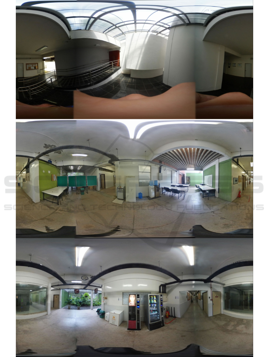
Figure 14: Panorama images generated using our method. Top image was captured with the C200 camera model and the
others with the R210 camera model.
Using Local Refinements on 360 Stitching from Dual-fisheye Cameras
25

Brown, M. and Lowe, D. G. (2007). Automatic panoramic
image stitching using invariant features. International
Journal of Computer Vision, 74(1):59–73.
Dhiman, A., Alapati, J., Parameswaran, S., and Ahn, E.
(2018). A method to generate ghost-free hdr images
in 360 degree cameras with dual fish-eye lens. In
2018 IEEE International Conference on Multimedia
and Expo (ICME), pages 1–6. IEEE.
Dissanayake, V., Herath, S., Rasnayaka, S., Seneviratne,
S., Vidanaarachchi, R., and Gamage, C. (2015).
Quantitative and qualitative evaluation of performance
and robustness of image stitching algorithms. In
2015 International Conference on Digital Image
Computing: Techniques and Applications (DICTA),
pages 1–6. IEEE.
Dong, Y., Pei, M., Zhang, L., Xu, B., Wu, Y., and Jia, Y.
(2019). Stitching videos from a fisheye lens camera
and a wide-angle lens camera for telepresence robots.
arXiv preprint arXiv:1903.06319.
Gao, J., Li, Y., Chin, T.-J., and Brown, M. S. (2013).
Seam-driven image stitching. In Eurographics (Short
Papers), pages 45–48.
Gao, W. and Shen, S. (2017). Dual-fisheye omnidirectional
stereo. In 2017 IEEE/RSJ International Conference
on Intelligent Robots and Systems (IROS), pages
6715–6722. IEEE.
Ghosh, D., Park, S., Kaabouch, N., and Semke, W.
(2012). Quantitative evaluation of image mosaicing in
multiple scene categories. In 2012 IEEE International
Conference on Electro/Information Technology, pages
1–6. IEEE.
Ho, T. and Budagavi, M. (2017). Dual-fisheye lens
stitching for 360-degree imaging. In 2017 IEEE
International Conference on Acoustics, Speech and
Signal Processing (ICASSP), pages 2172–2176. IEEE.
Ho, T., Schizas, I. D., Rao, K. R., and Budagavi, M.
(2017). 360-degree video stitching for dual-fisheye
lens cameras based on rigid moving least squares.
In 2017 IEEE International Conference on Image
Processing (ICIP), pages 51–55.
Jia, J. and Tang, C.-K. (2008). Image stitching using
structure deformation. IEEE Transactions on Pattern
Analysis and Machine Intelligence, 30(4):617–631.
Kwatra, V., Sch
¨
odl, A., Essa, I., Turk, G., and Bobick, A.
(2003). Graphcut textures: Image and video synthesis
using graph cuts. In ACM SIGGRAPH 2003 Papers,
SIGGRAPH ’03, pages 277–286, New York, NY,
USA. ACM.
Lo, I., Shih, K., and Chen, H. H. (2018). Image
stitching for dual fisheye cameras. In 2018 25th
IEEE International Conference on Image Processing
(ICIP), pages 3164–3168.
Schaefer, S., McPhail, T., and Warren, J. (2006). Image
deformation using moving least squares. In ACM
transactions on graphics (TOG), volume 25, pages
533–540. ACM.
Souza, T., Roberto, R., Lima, J. P., Teichrieb, V., Quintino,
J., Silva, F., Santosa, A., and Pinho, H. (2018).
360 stitching from dual-fisheye cameras based on
feature cluster matching. In Conference on Graphics,
Patterns and Images, SIBGRAPI 2018. SBC.
Szeliski, R. (2006). Image alignment and stitching.
In Handbook of Mathematical Models in Computer
Vision.
Times, N. Y. (2016). 360 video example. https://www.
youtube.com/watch?v= Ar0UkmID6s. [Online] Last
access 2019-06-19.
Times, N. Y. (2017). 360 degree video. https://www.
nytimes.com/video/360-video. [Online] Last access
2019-06-19.
Zia, O., Kim, J.-H., Han, K., and Lee, J. W. (2019). 360
◦
panorama generation using drone mounted fisheye
cameras. In 2019 IEEE International Conference on
Consumer Electronics (ICCE), pages 1–3. IEEE.
VISAPP 2020 - 15th International Conference on Computer Vision Theory and Applications
26
