
RANSAC for Aligned Planes with Application to Roof Plane Detection in
Point Clouds
Steffen Goebbels and Regina Pohle-Fröhlich
Institute for Pattern Recognition, Faculty of Electrical Engineering and Computer Science,
Keywords:
RANSAC, Building Reconstruction, CityGML.
Abstract:
Random Sample Consensus (RANSAC) is a standard algorithm to recognize planes in point clouds. It does
not require additional context information. However, it might be applied in situations where results can be
improved based on domain knowledge. Such a situation is 3D building reconstruction from airborne laser
scanning data. The normals of many roof facets are orthogonal to footprint vectors. This specific property
helps to estimate roof planes more precisely. The paper describes the adapted RANSAC algorithm. It can be
also used in other applications in which planes are aligned to supporting vectors.
1 INTRODUCTION
Semantic city models consist of building objects that
are composed from walls, roof facets, windows, doors
etc. Each wall and roof facet is defined by a pla-
nar polygon. Typically, such models are represented
in CityGML, see (Gröger et al., 2012). One can re-
construct roofs from point clouds (often obtained by
airborne laser scanning) using a model-driven, a data-
driven or a hybrid approach that combines model- and
data-driven methods, see (Tarsha-Kurdi et al., 2007b).
In a model-driven approach, parameterized standard
roofs from a catalogue are fitted to segments of the
point cloud. This works well for standard roofs but
not for scenic buildings like churches. Data driven
methods detect single planes and combine them to
a watertight roof (see e. g. (Elbrink and Vosselman,
2009; Kada and Wichmann, 2013)). To estimate such
planes in point clouds, Random Sample Consensus
(RANSAC) is a standard means, cf. (Yan et al., 2012),
(Chen et al., 2014). It is regarded to lead to better
results than the Hough transform (see (Tarsha-Kurdi
et al., 2007a)). Our motivation is to improve roof
plane detection with RANSAC in the context of data
driven building reconstruction.
RANSAC was introduced as a much more gen-
eral concept by Fischler and Bolles in (Fischler and
Bolles, 1981). When applied to plane detection, the
algorithm iteratively selects three (different) points.
These points determine a plane if they are non-
collinear. Then the algorithm counts inliers of this
plane. An inlier is a point with a distance to the
plane below a threshold value. In the original pa-
per, the plane is chosen if the number of inliers ex-
ceeds another threshold value. Otherwise, the iter-
ation is continued. To avoid this threshold parame-
ter, in a common variant of RANSAC a predefined
number of iterations is completed. Then a plane with
a maximum count of inliers is chosen. The concept
can be easily generalized to detect other geometric
primitives (see the original paper (Fischler and Bolles,
1981) and, for example, (Schnabel et al., 2007) for
some literature overview). In fact, RANSAC can
be used to fit standard roofs in a model-driven ap-
proach, see (Henn et al., 2013) for a combination of
RANSAC with machine learning. Due to our applica-
tion of data-driven building model generation, we ex-
clusively have to deal with planes. An important ad-
vantage is that RANSAC is robust against noise (cf.
(Roth and Levine, 1993)) like, in our case, (sparse)
vegetation, chimneys or antennas. A major disad-
vantage is computational cost. However, we do seg-
ment areas of possible roof planes prior to applying
RANSAC. Such local point selection does speed-up
the algorithm, see (Chen et al., 2014) and formula (3).
Processing time becomes no issue.
RANSAC is independent of additional domain
knowledge. It can be improved if additional informa-
tion are given. For roof reconstruction, results can be
enhanced by taking into account not only the number
of inliers but also the variance of their distances to the
candidate plane, see (Tarsha-Kurdi et al., 2008). A
Goebbels, S. and Pohle-Fröhlich, R.
RANSAC for Aligned Planes with Application to Roof Plane Detection in Point Clouds.
DOI: 10.5220/0008836301930200
In Proceedings of the 15th International Joint Conference on Computer Vision, Imaging and Computer Graphics Theory and Applications (VISIGRAPP 2020) - Volume 1: GRAPP, pages
193-200
ISBN: 978-989-758-402-2; ISSN: 2184-4321
Copyright
c
2022 by SCITEPRESS – Science and Technology Publications, Lda. All rights reserved
193

Figure 1: Roof planes were estimated with standard
RANSAC on areas with homogeneous gradient directions
of an airborne laser scanning point cloud: they are not per-
fectly aligned with footprint vectors.
more general approach is presented in (Saval-Calvo
et al., 2015). Prior to RANSAC estimation, this
method performs data clustering. Then planes are
estimated iteratively on the clusters and evaluated
by using domain specific constraints between clus-
ters. Based on initial estimates, likely inter-plane re-
lations (parallelism, orthogonality, etc.) can be es-
tablished using optimization methods, e.g., see (Mon-
szpart et al., 2015). In contrast to these additional
alignment procedures, we directly consider simple,
a-priori given domain knowledge within RANSAC.
This knowledge is that most roof facets’ normals
should be orthogonal to a footprint edge. Footprint
vectors are available in cadastral data. Also, many
methods exist to extract footprints from point clouds
or aerial images, cf. (Zeng et al., 2013). The main
contribution of this paper is to utilize this knowledge
to obtain estimated planes with normals that are prop-
erly aligned to footprint edges without the need of
additional aligning procedures, see Figure 1. This
is achieved in two steps, an extension to RANSAC
that is described in the next section, and an optimiza-
tion step that minimizes distances between inliers and
plane with respect to keeping the alignment, see Sec-
tion 3. We used these algorithms to compute a city
model. Section 4 summarizes results.
2 ALGORITHM
2.1 Footprint Directions
Let p ∈R
2
be a vector, then we denote its two compo-
nents by p.x and p.y. For vectors in R
3
we denote the
third component by p.z. Let G := {g
1
,...,g
n
} ⊂ R
2
be a set of normalized footprint directions such that
kg
k
k
2
:=
p
g
k
.x
2
+g
k
.y
2
= 1.
We cluster footprint edges. Each cluster contains
edges that point into the same or into the opposite di-
rection or are orthogonal to these directions (see dark
blue vectors in Figure 2). For each cluster, we sum
up the lengths of its edges. A most dominant direc-
tion is given by a cluster with a largest sum. For most
buildings, it is sufficient that set G consists only of the
most dominant direction. However, we also consider
directions of all other clusters that have a sum above
an application dependent threshold value of 2m.
Figure 2: The footprint of the building leads to only one
cluster of footprint directions. This cluster is defined by the
four dark blue vectors. Red vectors are plane normals. Their
projections onto a horizontal plane are drawn in yellow and
have to be aligned to the dark blue footprint directions. The
light blue vectors enclose 45° angles with the footprint di-
rections and might also serve for alignment (cf. Section 4.)
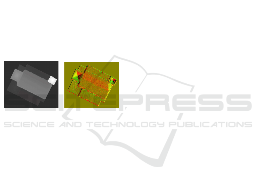
2.2 Segmentation of Areas with
Homogeneous Gradient Directions
If one directly uses RANSAC in connection with
complex roof layouts, it is possible to detect spuri-
ous planes that do not match with roof facets. For
example, such planes can be supported incidentally
by points belonging to different parts of the roof such
that these planes intersect with several real roof facets
that provide inliers. To avoid such artifacts, one has
to consider homogeneity of additional local features
like gradients or normals, cf. (Schnabel et al., 2007),
(Demir, 2018), (Poz and Ywata, 2019). RANSAC can
be modified by using a soft threshold voting function
based on this features, see (Xu et al., 2015). An-
other approach is to combine RANSAC with com-
putation of Normal Distribution Transformation cells,
see (Li et al., 2017). We follow the pre-segmentation
approach described in (Goebbels and Pohle-Fröhlich,
2017) and the literature cited there. Solid structures
in airborne laser scanning data basically are 2.5D.
This can be utilized to represent a building’s roof
by a height-map image. The image can be gener-
ated based on a 2.5D triangulation of the sparse point
cloud. On this height-map, flat and non-flat roof re-
gions can be distinguished according to the lengths of
gradients. Then non-flat roof regions can be further
segmented according to homogeneous gradient direc-
tions, see Figure 3. To this end, one can determine the
minima of a (smoothed) histogram of angles between
GRAPP 2020 - 15th International Conference on Computer Graphics Theory and Applications
194
gradients and x-axis. Then angles between two con-
secutive minima define a cluster. Gradient directions
with angles belonging to the same cluster are consid-
ered as homogeneous. We determine laser scanning
points within connected components of such homo-
geneous height-map areas and apply RANSAC to this
rather small filtered point clouds. Although height-
map gradients approximately point into the same di-
rection, the corresponding filtered point cloud might
support multiple planes with different slopes (see left
roof facets in Figure 2). It also may contain noise.
Even a mean gradient direction might not be suffi-
ciently precise to be used in plane detection because
angle clusters are broad due to the interpolation tech-
nique that leads to height-maps. Thus one cannot di-
rectly fit a plane to a filtered point cloud by using
regression approaches, segmentation does not make
RANSAC unnecessary. However, apart from exclud-
ing spurious planes, filtering to smaller clouds does
improve RANSAC performance very significantly.
Figure 3: The left image is a height-map generated from
laser scanning points by interpolation. Grey-values corre-
spond to heights. Gradients on that height-map are visual-
ized through colors in the right image by mapping their x-
and y-coordinates to the red and green channels. Homoge-
neously colored areas are used to segment the point cloud
such that RANSAC can be applied on segments.
For each connected component, we detect planes
iteratively using the algorithm that is described in the
next section. After identifying a plane, we remove
its inliers from the corresponding filtered point cloud.
Iterations terminate if numbers of inliers are below a
threshold value.
2.3 RANSAC with Footprint Alignment
As standard RANSAC does, our variant also itera-
tively selects three points p
1
, p
2
, and p
3
. Within
each iteration it computes a plane and counts the in-
liers if the selected points are non-collinear. In the
end, a plane with the maximum number of inliers is
selected. To avoid fragmented roofs, the (continued)
selection of planes with largest inlier counts appears
to be more suited than choosing planes with inlier
counts above a threshold value. So far, there is no
difference to standard RANSAC implementations. It
is also quite common (and already suggested in (Fis-
chler and Bolles, 1981)) to improve the result by op-
timally fitting a plane through the best plane’s inlier
points. What makes our algorithm different is how
the planes are determined if they are closely aligned
to footprint edges.
Standard RANSAC directly computes a Hesse
normal form that describes a plane through the se-
lected three points. Using the outer product, one gets
a normal
n
0
:=
(p
2
−p
1
) ×(p
3
−p
1
)
k(p
2
−p
1
) ×(p
3
−p
1
)k
2
and a signed distance to the origin
0 that is given by
the inner product
ρ
0
:=<n
0
,p
1
>:=n
0
.x·p
1
.x+n
0
.y·p
1
.y+n
0
.z·p
1
.z.
A point p lies on this plane iff <n
0
,p >= ρ
0
.
We use normals that point upwards (“sign” de-
notes the signum function):
n
1
:= sign(n
0
.z) ·n
0
, ρ
1
:= sign(n
0
.z) ·ρ
0
.
Therefore, n
1
.z ≥ 0. If n
1
.z ≈ 0 then the plane does
not belong to a roof but to a wall. Thus, we can as-
sume n
1
.z > 0. A flat roof is obtained iff n
1
.z ≈ 1. In
this case, we replace the normal by (0, 0, 1) and adjust
the distance ρ
1
to
0 by using the arithmetic mean of
all inliers’ z-coordinates (see Algorithms 1 and 3). In
what follows we discuss the main case 0 <n
1
.z < 1.
Most but not all roof facets might be aligned to
footprint edges. We replace the normal n
1
by an ad-
justed one that is orthogonal or parallel to a footprint
direction iff the difference angle between both nor-
mals is small. To this end, let α > 0 be a thresh-
old angle near 0. We determine angles between foot-
print directions g
k
∈ G (as well as orthogonal vectors
(−g
k
.y,g
k
.x)) and projections of the normal vectors
to the x-y-plane by computing inner products. To
this end, let n
2
:= (n
1
.x,n
1
.y)/k(n
1
.x,n
1
.y)k
2
. For
k ∈ {1,...,n} let
c
k
:= n
2
.x ·g
k
.x +n
2
.y ·g
k
.y,
d
k
:= n
2
.x ·(−g
k
.y) +n
2
.y ·g
k
.x.
• If |c
k
0
| = max{|c
k
|,|d
k
| : k ∈ {1, . . . , n}} and
|c
k
0
|> cos(α) then we change the direction of the
normal in the x-y-plane depending on the sign of
c
k
0
. Its new normalized direction is
h := sign(c
k
0
) ·g
k
0
.
• Otherwise, if |d
k
0
| = max{|c
k
|,|d
k
| : k ∈
{1,...,n}} and |d
k
0
| > cos(α), we change
the direction according to
h := sign(d
k
0
) ·g
k
0
.
RANSAC for Aligned Planes with Application to Roof Plane Detection in Point Clouds
195

• Otherwise, no footprint vector can be used for
alignment. However, some roofs have facets with
normals that, if projected to the ground plane,
enclose 45° angles with footprint edges. To
also consider these directions, one could now re-
place directionsg
k
by [g
k
+(−g
k
.y,g
k
.x)]/
√
2, re-
compute c
k
and d
k
and re-perform previous two
cases.
For the first two cases, we replace the normaln
1
with
n := (l ·
h.x,l ·
h.y,
p
1 −l
2
) (1)
such that knk
2
= 1. Please note that the z-component
can be chosen to be positive because
h points approx-
imately into the same direction as n
1
within the x-
y-plane. To specify parameter l, let indices i 6= j ∈
{1,2,3} be chosen such that b, defined by
a := (p
i
.x −p
j
.x)
h.x + (p
i
.y −p
j
.y)
h.y,
b :=
|a|
p
(p
i
.x −p
j
.x)
2
+ (p
i
.y −p
j
.y)
2
,
becomes maximal. Due to non-collinearity of points
and because walls are excluded, b > 0 and vectors
(p
i
.x −p
j
.x,p
i
.y −p
j
.y) and
h are as close as pos-
sible to being parallel. Then parameter 0 ≤ l < 1 is
determined such that the vector p
i
−p
j
becomes or-
thogonal to n. Thus, we require
0 =< (p
i
−p
j
),n >= l ·a +
p
1 −l
2
(p
i
.z −p
j
.z)
such that l
2
a
2
= (1 −l
2
)(p
i
.z −p
j
.z)
2
and
l =
|p
i
.z −p
j
.z|
p
a
2
+ (p
i
.z −p
j
.z)
2
if p
i
.z −p
j
.z 6= 0 and l := 0 otherwise. The adjusted
Hesse normal form then is given by normaln, see (1),
and signed distance ρ :=< p
i
,n > between
0 and the
plane. Due to construction, the two points p
i
and p
j
lie on this aligned plane. Algorithm 1 summarizes the
computation of plane parameters.
As in many RANSAC implementations, the plane
with the largest number of inliers of all iterations is
selected. Inliers of a plane with parameters (n, ρ) are
points of the point cloud (segment) P with a shortest
distance to the plane that is less then a threshold value
δ, i.e., a point p ∈ P ⊂ R
3
is an inlier with respect
to n, ρ, and δ iff | < p,n > −ρ| < δ, see Algorithm
2. Let I be the corresponding set of inliers. Instead
of just counting inliers, one could also consider the
variance of distances between inliers and their plane
to select a best plane, cf. (Tarsha-Kurdi et al., 2008).
However, our post processing procedure in Section 3
already does minimize variance of distances between
inliers and plane. Depending on available data, other
Algorithm 1 : Estimation of a plane’s Hesse normal form;
the algorithm returns a pair of normal vector and signed dis-
tance between plane and origin.
procedure GETPLANEPARMS(p
1
, p
2
, p
3
, G)
n
0
:=
(p
2
−p
1
)×(p
3
−p
1
)
k(p
2
−p
1
)×(p
3
−p
1
)k
2
ρ
0
:=<n
0
,p
1
>
if n
0
.z ≈ 0 then return (n
0
,ρ
0
) wall plane
n
1
:= sign(n
0
.z) ·n
0
ρ
1
:= sign(n
0
.z) ·ρ
0
if n
1
.z ≈ 1 then return ((0,0, 1),ρ
1
) flat roof
n
2
:= (n
1
.x,n
1
.y)/k(n
1
.x,n
1
.y)k
2
.
m := −1
for g ∈ G do
c :=n
2
.x ·g.x +n
2
.y ·g.y
if |c| > cos(α) ∧|c| > m then
h := sign(c) ·g
m := |c|
d :=n
2
.x ·(−g.y) +n
2
.y ·g.x
if |d| > cos(α) ∧|d| > m then
h := sign(d) ·g
m := |d|
if m = −1 then return (n
1
,ρ
1
)
normal can be adjusted
r
1
:= p
1
−p
2
,r
2
:= p
2
−p
3
,r
3
:= p
1
−p
3
for i ∈ {1,2,3} do
a
i
:=r
i
.x ·
h.x +r
i
.y ·
h.y
b
i
:= |a
i
|/
p
r
i
.x
2
+r
i
.y
2
for i ∈ {1,2,3} do
if b
i
= max{b
1
,b
2
,b
3
} then
a := a
i
,r :=r
i
, p := p
i
ifr.z = 0 then l:=0;
else
l :=
|r.z|
√
a
2
+r.z
2
n := (l ·
h.x,l ·
h.y,
√
1 −l
2
)
return (n,< p,n >)
strategies for defining inliers might be helpful. In case
of a colored point cloud, one could additionally match
color information, see (Adam et al., 2018). Instead of
searching for inliers in the original point cloud, we
also tested with points obtained from the 2.5D height-
map, equidistantly arranged in the x-y-plane. We ex-
pected that, due to interpolation, some artificial step
edges between roof facets could be avoided. But only
in rare cases a different plane was selected as best fit-
ting.
It is well known (see (Fischler and Bolles, 1981))
that standard RANSAC at least needs
i ≥ ln(1 − p)/ln
1 −
|I|
|P|
3
!
(2)
iterations to find three inlier points of a specific plane
with a probability of at least p. For this specific plane,
|I|/|P| is the probability to randomly select one inlier,
where |I| is the number of all inliers of this plane and
GRAPP 2020 - 15th International Conference on Computer Graphics Theory and Applications
196

|P| is the size of the point cloud. Thus 1 −(|I|/|P|)
3
is the probability to independently draw three points
from P such that at least one is no inlier. The chance
that this happens in each of i independent experiments
is (1 −(|I|/|P|)
3
)
i
. This probability has to be less
than 1 − p which gives (2). The exponent 3 equals
the number of points needed to define the geomet-
ric primitive. The formula does not consider that
collinear inliers could be selected. To reduce the prob-
ability of getting collinear points, it is better to draw
three points without repetition, i.e., to draw three dif-
ferent points. Then points are no longer drawn inde-
pendently. Instead of multiplying probabilities to get
p
3
, the probability
|I|
3
|P|
3
=
|I|
|P|
·
|I|−1
|P|−1
·
|I|−2
|P|−2
now is given by the hypergeometric distribution, i.e.,
i ≥ ln(1 − p)/ln
1 −
|I|
|P|
·
|I|−1
|P|−1
·
|I|−2
|P|−2
. (3)
In order to use formulas (2) or (3) as a lower bound for
the number of RANSAC iterations, one has to con-
servatively estimate inlier ratio µ :=
|I|
|P|
and replace
unknown |I| by µ ·|P|.
But even three pairwise different points could lie
on a straight line. Since the two-dimensional vol-
ume of any finite union of straight lines is zero, the
probability of randomly scanning a point that pre-
cisely lies on at least one line through any two pre-
viously scanned points is zero. However, laser scan-
ners do not place points randomly but in stripes. Then
the probability of finding three collinear inliers de-
pends on unknown geometric properties. For exam-
ple, if we assume a regular
p
|P|×
p
|P| grid for x-y-
coordinates (that occurs if one applies RANSAC on a
2.5D height-map) then at most
p
|P| inliers can lie on
a line. We assume
p
|P| < |I|. Then with
ln(1 − p)/ln
1 −
|I|
|P|
·
|I|−1
|P|−1
·
|I|−
p
|P|
|P|−2
!
iterations, the probability to get three non-collinear
inliers is above p.
Even if three non-collinear points are drawn, they
lie within threshold distance but probably not exactly
on the specific plane we are looking for. A plane that
is supported by the three points might have an inlier
count that differs from the count of the specific plane.
This are all reasons to consider additional iterations.
Algorithm 2 : RANSAC for roof plane detection in point
cloud P using footprint directions in set G. Number of iter-
ations is i, threshold value δ > 0 is used to define inliers.
procedure GETINLIERS(n, ρ, P, δ)
I :=
/
0
for p ∈ P do
if | < p,n > −ρ| < δ then
I := I ∪{p}
return I
procedure RANSAC(P, G, i, δ)
I
best
:=
/
0, k = 1
while (k ≤i) ∧(|I
best
| < |P|) do
randomly select different points p
1
,p
2
,p
3
∈ P
if det[p
1
,p
2
,p
3
] 6= 0 then non-collinear points
(n,ρ) := GETPLANEPARMS(p
1
, p
2
, p
3
, G)
if n.z 6≈0 then no wall
I:=GETINLIERS(n, ρ, P, δ)
if |I| > |I
best
| then
I
best
:= I, n
best
:=n, ρ
best
:= ρ
k := k + 1
if |I
best
| > 2 then return (n
best
,ρ
best
,I
best
)
else
return “no plane found”
3 OPTIMIZING PLANES’ SLOPES
RANSAC provides a plane with a maximum number
of inliers. However, there might exist a different plane
with the same set of inliers but smaller distances be-
tween inliers and plane. While keeping alignment to
footprint vectors, we find such a “better” plane by
applying a principal component analysis (PCA), see
Figure 4. For building model reconstruction, most es-
timated planes are indeed aligned to footprint direc-
tions (see Section 4). Thus, we have to find an optimal
value for a parameter l such that shortest distances be-
tween inliers and plane become minimal with a nor-
!
δ
!
δ
Figure 4: The bold red and blue lines visualize cuts through
planes that are already aligned to a footprint vector. Both
planes have the same inliers (black dots) with respect to
a threshold value δ. But the sum of squared distances
(squared lengths of thin blue lines in case of the blue plane)
is not minimal for both planes. A best fitting plane should
be computed.
RANSAC for Aligned Planes with Application to Roof Plane Detection in Point Clouds
197

mal vector
n
opt
:=
l ·
d.x, l ·
d.y,
p
1 −l
2
(4)
where
d =
(n.x,n.y)
k(n.x,n.y)k
2
. This means that we maintain
the direction of the normal vector with respect to its
x- and y-coordinates. If aligned to a footprint direc-
tion, a plane keeps aligned. To find l, we orthogo-
nally project all inliers to the plane spanned by vec-
tors (
d.x,
d.y,0) and (0,0,1). The origin
0 lies on this
plane. For numerical stability it might be required to
shift the plane by adding an inlier such that numbers
become smaller. We add inlier q
1
which is element of
the set I := {q
1
,...q
m
} ⊂ R
3
of all inliers. We obtain
the 2D set of projections {
t
1
,...
t
m
} ⊂ R
2
via
t
k
.x := < (q
k
−q
1
),(
d.x,
d.y,0) >,
t
k
.y := < (q
k
−q
1
),(0,0,1) >=q
k
.z −q
1
.z.
For this set, we perform a PCA to find the best fitting
line. To obtain the covariance matrix
C =
σ
2
x
σ
xy
σ
xy
σ
2
y
,
let
t :=
1
m
∑
m
k=1
t
k
be the center of gravity of the 2D
points,
σ
2
x
:=
∑
m
k=0
(
t.x −
t.x)
2
m −1
, σ
2
y
:=
∑
m
k=0
(
t.y −
t.y)
2
m −1
,
σ
xy
:=
1
m −1
m
∑
k=0
(
t.x −
t.x)(
t.y −
t.y).
A largest eigenvalue of C or (m −1)C is
λ =
σ
xx
+ σ
yy
2
+
r
(σ
xx
+ σ
yy
)
2
4
−(σ
xx
σ
yy
−σ
2
xy
),
a corresponding eigenvector e is given via
(−σ
xy
,σ
2
x
− λ) or (σ
2
y
− λ,−σ
xy
) if non-zero.
Parameter l of n
opt
in (4) has to be chosen such that
(l,
√
1 −l
2
) becomes orthogonal to e, i.e.,
l ·e.x +
p
1 −l
2
·e.y = 0
such that l
2
·(e.x)
2
= (1 −l
2
) ·(e.y)
2
. The positive
solution is l = |e.y|/kek
2
. With the optimized normal
n
opt
, the signed distance between plane and
0 has to
be updated as well. To this end, we use the center of
gravity of projected points:
ρ
opt
:=< (q
1
.x +
t.x ·
d.x,q
1
.y +
t.x ·
d.y,
t.y),n
opt
> .
The optimization procedure is summarized in Algo-
rithm 3.
After all roof planes of a building are determined,
the data-driven approach of roof reconstruction can
be combined with model knowledge. Typically, a
building only has very few different roof slopes. By
clustering z-components of normals, similar z-values
can be adjusted to a mean value. Also, similar fa-
cade heights can be balanced by adjusting distances
of planes to the origin.
Algorithm 3: Optimization of plane parameters.
procedure OPTIMIZEPLANE(n, ρ, I)
d =
(n.x,n.y)
k(n.x,n.y)k
2
T :=
/
0 T is a multiset or list.
t :=
0 ∈R
2
select an inlier q
1
∈ I.
for q ∈ I do
t.x :=< (q −q
1
),(
d.x,
d.y,0) >
t.y :=q.z −q
1
.z.
T := T ∪{
t},
t :=
t +
t,
t :=
t/|I|,
if n.z = 1 then return (n,
t.y)
else
s
2
x
:= s
2
y
:= s
xy
:= 0
for
t ∈T do
s
2
x
:= s
2
x
+ (
t.x −
t.x)
2
, s
2
y
:= s
2
y
+ (
t.y −
t.y)
2
s
xy
:= s
xy
+ (
t.x −
t.x)(
t.y −
t.y)
λ :=
s
xx
+s
yy
2
+
q
(s
xx
+s
yy
)
2
4
−(s
xx
s
yy
−s
2
xy
)
e
1
:= (−s
xy
,s
2
x
−λ), e
2
:= (s
2
y
−λ, −s
xy
)
if ke
1
k
2
> ke
2
k
2
then e :=e
1
else
if ke
2
k
2
> 0 then e :=e
2
else e := (1,0)
l :=
|e.y|
kek
2
n
opt
:=
l ·
d.x,l ·
d.y,
√
1 −l
2
ρ
opt
:=< (q
1
.x+
t.x ·
d.x,q
1
.y+
t.x ·
d.y,
t.y),n
opt
>
return (n
opt
,ρ
opt
)
4 RESULTS
We tested with data of one square kilometer.
It belongs to the city of Dortmund and cov-
ers zone 32U UTM-interval [393000,394000] ×
[5703000,5704000], see Figure 5. This area consists
of 1,591 buildings or building parts. We chose α = 5°
as a threshold angle for aligning with footprint di-
rections and δ = 0.1m as threshold distance to de-
fine inliers. This value is compliant with precision
of airborne laser scanning. Due to pre-segmentation
and analysis of our data, we conservatively expected
more than µ = 30% of points to be inliers of the largest
plane to be detected with each call of RANSAC. For
large point clouds P we can approximate (3) with (2).
If we want to find three inliers of the largest plane
with a probability of 99.999% then we should con-
sider more than 420 iterations. For conservative re-
sults, we used 500 RANSAC iterations in which three
pairwise different (but not necessarily non-collinear)
points were selected. With these parameters and
because of pre-segmentation, detected planes had a
mean inlier ratio of 89.5%, see Figure 6. The 0.25-
quantile is 81.9% such that only 15 iterations would
GRAPP 2020 - 15th International Conference on Computer Graphics Theory and Applications
198
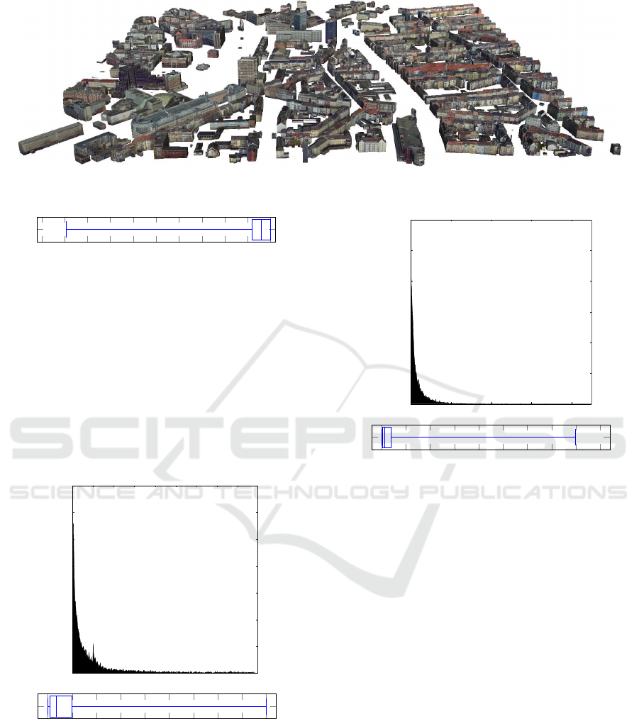
Figure 5: Test data: Our variant of RANSAC was used to estimate roof facets of this model of a square kilometer of the city
of Dortmund.
0 0.1 0.2 0.3 0.4 0.5 0.6 0.7 0.8 0.9 1
Figure 6: Boxplot of best planes’ inlier ratios.
have been sufficient to detect 75% of model planes.
When considering only footprint directions with a
minimum length of 2 m, 7,616 facet normals of non-
flat roofs were at least slightly aligned. The remaining
2,845 facets of non-flat roofs pointed into different
directions.
The mean change of x-y-projections of best fitting
planes’ normals was 1.5°. The diagrams in Figure 7
show the distribution of smallest angles between foot-
print edges and projected original, non-adjusted nor-
mals of best fitting planes.
! " #! #" $! $" %! %" &!
!
#!!
$!!
%!!
&!!
"!!
'!!
()*+,
)-./,012314+(),5
0 5 10 15 20 25 30 35 40 45
Figure 7: Minimum angles between estimated plane nor-
mals (projected to the x-y-plane) and footprint directions.
The effect of PCA normalization for non-flat roofs
is shown in Figure 8. The average change of normal
angles is 1.67°. Indeed, the optimization step does
contribute to the quality of estimated planes.
! "! #! $! %!
!
#!!
%!!
&!!
'!!
"!!!
"#!!
()*+,
)-./,012314+(),5
0 5 10 15 20 25 30 35 40 45
Figure 8: Angle changes due to PCA optimization.
If one also allows alignment to lines that enclose
45° angles with footprint vectors then 7,926 out of
10,461 non-flat roof facets were aligned.
5 CONCLUSIONS
The described method is limited to planar roof facets.
Although changes of models are not immediately vis-
ible, more precise roof geometries can be obtained by
aligning normal vectors to footprint directions. This
makes it easier to maintain planarity of roof facets
when combining them without introducing artificial
step edges. In some cases, aligned roof facets also re-
duce the number of roof polygons. Alignment can be
used to speed-up RANSAC. In our application, most
but not all the planes can be aligned to a footprint vec-
tor. However in case of alignment, the footprint vector
could be selected due to our pre-segmentation accord-
ing to gradient angles. If such additional information
is available for all planes to be detected, one can use
two instead of three (non-collinear) points to define a
RANSAC for Aligned Planes with Application to Roof Plane Detection in Point Clouds
199

plane. Then only
ln(1 − p)
ln
1 −
|I|
|P|
·
|I|−1
|P|−1
<
ln(1 − p)
ln
1 −
|I|
|P|
·
|I|−1
|P|−1
·
|I|−2
|P|−2
iterations are required to find different inliers of the
plane with probability p, see (3). Future work could
incorporate texture information from oblique areal
images.
ACKNOWLEDGEMENTS
We thank Cornelia Herrmann-Hahn from Dortmund
cadastral office for inspiring this work.
REFERENCES
Adam, A., Chatzilari, E., Nikolopoulos, S., and Kompat-
siaris, I. (2018). H-RANSAC: A hybrid point cloud
segmentation combining 2D and 3D data. ISPRS Ann.
Photogramm. Remote Sens. and Spatial Inf. Sci., IV-
2:1–8.
Chen, D., Zhang, L., Mathiopoulos, P. T., and Huang,
X. (2014). A methodology for automated segmenta-
tion and reconstruction of urban 3-D buildings from
ALS point clouds. IEEE Journal of Selected Topics
in Applied Earth Observations and Remote Sensing,
7(10):4199–4217.
Demir, N. (2018). Automated detection of 3D roof planes
from lidar data. Journal of the Indian Society of Re-
mote Sensing, 46(8):1265–1272.
Elbrink, S. O. and Vosselman, G. (2009). Building recon-
struction by target based graph matching on incom-
plete laser data: analysis and limitations. Sensors,
9(8):6101–6118.
Fischler, M. A. and Bolles, R. C. (1981). Random sample
consensus: a paradigm for model fitting with appli-
cations to image analysis and automated cartography.
Communications of the ACM, 24(6):381–395.
Goebbels, S. and Pohle-Fröhlich, R. (2017). Quality en-
hancement techniques for building models derived
from sparse point clouds. In Proc. International Con-
ference on Computer Graphics Theory and Applica-
tions (GRAPP) 2017, pages 93–104, Porto.
Gröger, G., Kolbe, T. H., Nagel, C., and Häfele, K. H.
(2012). OpenGIS City Geography Markup Language
(CityGML) Encoding Standard. Version 2.0.0. Open
Geospatial Consortium.
Henn, A., Gröger, G., Stroh, V., and Plümer, L. (2013).
Model driven reconstruction of roofs from sparse li-
dar point clouds. ISPRS Journal of Photogrammetry
and Remote Sensing, 76:17–29.
Kada, M. and Wichmann, A. (2013). Feature-driven 3D
building modeling using planar halfspaces. ISPRS
Ann. Photogramm. Remote Sens. and Spatial Inf. Sci.,
II-3/W3:37–42.
Li, L., Yang, F., Zhu, H., Li, D., Li, Y., and Tang, L. (2017).
An improved RANSAC for 3D point cloud plane seg-
mentation based on Normal Distribution Transforma-
tion cells. Remote Sensing, 9(433):1–16.
Monszpart, A., Mellado, N., Brostow, G., and Mitra, N.
(2015). Rapter: Rebuilding man-made scenes with
regular arrangements of planes. ACM Transactions on
Graphics, 34:103:1–103:12.
Poz, A. P. D. and Ywata, M. S. Y. (2019). Adaptive random
sample consensus approach for segmentation of build-
ing roof in airborne laser scanning point cloud. Inter-
national Journal of Remote Sensing, online first:1–15.
Roth, G. and Levine, M. D. (1993). Extracting geometric
primitives. CVGIP: Image Underst., 58(1):1–22.
Saval-Calvo, M., Azorin-Lopez, J., Fuster-Guillo, A., and
Garcia-Rodriguez, J. (2015). Three-dimensional pla-
nar model estimation using multi-constraint knowl-
edge based on k-means and RANSAC. Applied Soft
Computing, 34:572–586.
Schnabel, R., Wahl, R., and Klein, R. (2007). RANSAC
based out-of-core point-cloud shape detection for city-
modeling. Schriftenreihe des DVW, Terrestrisches
Laser-Scanning (TLS 2007).
Tarsha-Kurdi, F., Landes, T., and Grussenmeyer, P. (2007a).
Hough-transform and extended RANSAC algorithms
for automatic detection of 3D building roof planes
from lidar data. ISPRS International Archives of Pho-
togrammetry, Remote Sensing and Spatial Informa-
tion Systems, XXXVI(W52):407–412.
Tarsha-Kurdi, F., Landes, T., and Grussenmeyer, P. (2008).
Extended RANSAC algorithm for automatic detection
of building roof planes from LIDAR data. The Pho-
togrammetric Journal of Finland, 21(7):97–109.
Tarsha-Kurdi, F., Landes, T., Grussenmeyer, P., and Koehl,
M. (2007b). Model-driven and data-driven ap-
proaches using LIDAR data: Analysis and com-
parison. International Archives of Photogrammetry,
Remote Sensing and Spatial Information Sciences,
36(3/W49A):87–92.
Xu, B., Jiang, W., Shan, J., Zhang, J., and Li, L. (2015).
Investigation on the weighted RANSAC approaches
for building roof plane segmentation from lidar point
clouds. Remote Sensing, 8(5):1–23.
Yan, J., Jiang, W., and Shan, J. (2012). Quality analysis on
RANSAC-based roof facets extraction from airborne
LIDAR data. International Archives of Photogramme-
try and Remote Sensing, XXXIX(B3):367–372.
Zeng, C., Wang, J., and Lehrbass, B. (2013). An evalua-
tion system for building footprint extraction from re-
motely sensed data. IEEE Journal of Selected Topics
in Applied Earth Observations and Remote Sensing,
6(3):1640–1652.
GRAPP 2020 - 15th International Conference on Computer Graphics Theory and Applications
200
