
Direct NC Toolpath Generation from 3D Point Cloud Datasets
Muslimin
1
*, Katerina Mukti
1
, Hasvienda M. Ridlwan
1
, M. Sholeh
1
, Ade Sumpena
1
, Jiang Zhu
2
,
Hayato Yoshioka
2
, Tomohisa Tanaka
3
1
Department of Mechanical Engineering, Politeknik Negeri Jakarta, Jl. Prof. Siwabewssy Kampus UI, Depok, Indonesia
2
Department of Mechanical Engineering, School of Engineering, Tokyo Institute of Technology
I1-35, 2-12-1, O-okayama, Meguro, Tokyo 152-8552, Japan
3
Laboratory for Future Interdisciplinary Research of Science and Technology (FIRST), Institute of Innovative Research
(IIR), Tokyo Institute of Technology, 2-12-1 Ookayama, Meguro, Tokyo 152-8550, Japan
Keywords: 3D point cloud data, direct tool path, reverse engineering, G-code
Abstract: In reverse engineering, the measurement of the object's surface is carried out by 3D scanning producing 3D
point cloud data. Scanning performed from various positions will have different data, which will then be
registered to form a product topography. The next process is to reconstruct 3D CAD, which is then converted
into working drawings, used for manufacturing processes such as CNC machining by generating G-Code. The
crucial stage was the 3D CAD reconstruction of the point cloud dataset, which required a complicated
triangulation process and long computation time. In this research, 3D point cloud data is used directly to
generate tool paths for CNC machining without 3D CAD reconstruction. The goal is to shorten the reverse
engineering time with a quality that can still meet the requirements. The stage is to model the tool path of the
tools used in CNC machining relative to feature point cloud sets. This toolpath will be used as the basis for
creating G-code. The toolpath makes it possible to degenerate directly from the verified 3D point cloud
registration data based on the modeling results.
1 INTRODUCTION
In reverse engineering, the measurement of an
object's surface is carried out using a 3D laser scan,
which produces 3D point cloud data sets. Scanning
from various positions will have different data, which
will then be registered to form a product topography.
The next stage is the CAD reconstruction of the data
points (Muslimin et al., 2015). CAD surfaces created
are usually in the form of a parametric computer
representation, such as B-helical, Bezier, non-
uniform rational surfaces, and so on. However, 3D
CAD reconstruction is complicated, time-consuming,
and requires operator expertise since accuracy is the
primary reverse engineering goal. Today's laser
scanners are equipped with 3D CAD reconstruction
software, but they are not compatible enough to
handle data noise, edge sharpness, holes, and so on
(Sun et al., 2002)(Muslimin et al., 2015). On the other
hand, the manufacturing process directly from the
point cloud data set without prior CAD reconstruction
is possibly implemented (Chui et al., 2002)(Makki et
al., 2011)(Liu et al., 2013).
Many manufacturing processes can apply to
realize product duplication directly from the point
cloud data set. The method includes additives using a
3D printer, CNC machines to duplicate molds and
moldings for molded products, forging products, and
permanent mold casting products, and so on. In the
additive manufacturing process using a 3D printer,
the point cloud dataset at x, y, z coordinates are
converted into STL format and can then be directly
processed by a 3D printer. In the CNC machining
An application by developing numerical control
(NC) pathways directly from a point cloud dataset is
proposed in this work. The tool path is restricted by
part material, cutter tools, cutting speeds, and work
features. The NC-tool way directly from the point
cloud data has been developed since the popular 3D
scanner used in the reverse technique (Chui et al.,
2002)(Yau & Hsu, 2009)(D. Zhang, 2009). However,
its effectiveness still needs further development. This
method includes NC tool line generators for 3-axis
milling (Zhang et al., 2010) and 5-axis milling (Marie
et al., 2004).
The tool path planning issues were how to make
more accurate machining and smoother, efficient NC-
138
Muslimin, ., Mukti, K., Ridlwan, H., Sholeh, M., Sumpena, A., Zhu, J., Yoshioka, H. and Tanaka, T.
Direct NC Toolpath Generation from 3D Point Cloud Datasets.
DOI: 10.5220/0010574100003153
In Proceedings of the 9th Annual Southeast Asian International Seminar (ASAIS 2020), pages 138-145
ISBN: 978-989-758-518-0
Copyright
c
2022 by SCITEPRESS – Science and Technology Publications, Lda. All rights reserved

tool paths to speed up the process and complete the
complex reconstruction process. This research's main
contribution is to propose an innovative method for
NC (numerical control) tool path generation directly
from a registered point cloud data set. The final goal
is to make a point cloud data conversion system into
G-code CNC machines in the reverse engineering
process.
2 LITERATUR REVIEW
Two critical objectives of the NC-tool path are
machining effectivity and accuracy. Machining
effectiveness deals with tool motions, consisting of
two methods: forward and sidestep. The forward step
is for the line portion connecting adjacent CC (cutter
contact) circumstances, and the highest permissible
chordal variation is called machining tolerance. The
machining accuracy deals with the geometry and
tolerance of the machining process's final result
compared to the specified target. Also, it deals with
surface finishing.
There are two approaches to converting the point
cloud dataset into NC toolpath, the direct and indirect
methods. The differences between the direct method
and indirect method in tool path creation from 3D
point cloud data set are as the following (Zhang,
2009):
1) Indirect tool path generation: In this method,
surface CAD model reconstruction is generated
from the point cloud dataset. Some CAD
software such as CATIA, SolidWorks, and
IMAGEWARE support surface remodeling from
3D point cloud data sets; however, it still needs
interaction from the users to get more precise
surface regeneration with advanced experience
in facade modeling.
2) Direct tool path generation: This method is used
directly from the point cloud dataset without
CAD image regeneration. Due to the inadequacy
of an underlying surface representation, there are
two problems:
a) It is challenging to obtain adaptive
advancing steps and track intervals, driving
to lower machining performance because
without a continuous surface.
b) It is laborious to restrain the machining
exactitude when the input is complex
geometry and noisy.
3 DIRECT NC TOOL PATH
GENERATION
In industry, 3-axis CNC machines are employed for
both the coarse and finish machining process.
Regularly, 3-axis machining techniques for complex
surfaces use a ball end mill cutter. The ball end mills
is a zero cutting speed at the bottom of the ball. This
issue can be overcome by using other cutter
geometries such as flat end mills or multi-axis tool
paths such as four axes or five axes CNC machines.
In this research, NC-milling is used because the
object is the prismatic shape. A three-axis tool path is
adopted for computation. The main steps of the
generation of an efficient NC tool path directly from
point cloud datasets registration proposed in this
research are as follows:
1) Orient the point cloud data with a machined
surface into the z-axis and consider the cutting
tool's direction. It is crucial to start the planning
of the tool path from (0,0,0).
2) Classify all main machined surfaces into
complex features and non-complex features.
Complex surfaces include free-form surfaces,
curves, and ruled surfaces.
3) Select the machining method, tool type, and tool
diameter and shape.
4) Establish a cutting step. Assume all process
consists of three stages of machining processes:
rough machining, semi-finishing, and finishing.
a) Rough machining: using 10 mm diameter of
a flat end mill cutting tool.
b) Semi-finishing: employing 5 mm diameter
of a ball end mill.
c) Finishing: Using 3 mm diameter of a ball
end mill.
Rough machining (flat-end mill)
a) Establish cutting range and the distance
between the cutting process using flat-end
mill parameters.
b) Establish space (allowance) for cutting.
c) Consider the forward steps and backward
steps of tools regarding point cloud
conditions. The grid method is applied to
evaluate the forward and backward steps of
tools so that there is no over-cut.
Semi-finishing cutting and Finish Cutting using
a ball-end mill.
a) Select the diameter of the cutter.
b) Establish cutting range and the distance
between the cutting process by using ball-
end mill parameters.
c) Establish space (allowance) for cutting.
Direct NC Toolpath Generation from 3D Point Cloud Datasets
139

d) Consider the forward steps and backward
steps of tools regarding point cloud
conditions. The grid method is used to
evaluate the forward and backward steps of
tools to no over-cutting.
e) Consider interpolation.
3.1 Method of Machining Type and
Tools Selection
In the selecting machining method, it can be
recognized easily by looking at the object's shape. If
the object shape is prismatic, the NC milling process
is chosen. On the other hand, if the object shape is
cylinder NC turning process is applied. The next step
is selecting the tools and parameters of the cutting
process. Single-step machining or multi-steps
machining can be considered depending on the
complexity of an object to be cut.
The selection of a milling cutter, according to the
six steps:
1) Define the operation type
2) Define the material of the workpiece.
3) Select the cutter concept
4) Select the milling cutter
5) Select the insert
6) Define the start values
Considering the feature type in the tools selection
is very important to ensure the machining process
(Lin & Koren, 1996).
3.2 Toolpath Planning Selection
The current tool path generation used has mainly two
steps. The first is to specify the cutter contact point,
often called cutter cutting (CC), on the part surface,
and then the second is to offset that point to yield the
cutter location (CL). The cutter cutting is the location
where the tool touches the part surface. There exist
some tool path generation methods that are popular in
the industry. Some of them are discussed in the next
sections.
Tool path patterns are commonly applied in NC-
path generating: parallel, iso-parametric method, iso-
planar method, isophote, constant scallop method,
and spiral.
The isoparametric method (Zou & Zhao, 2013) is
one of the simplest methods used to create a tool path.
In this method, the cutter contact positions are
specified along with the isoparametric lines on the
part surface. Isoparametric lines are curves of
constant parameter value on the parametric body.
Linear segments usually approximate the
isoparametric track. However, if the linear features
are extensive, it may result in undercuts on the
model's surfaces, which are already machined in the
previous operation.
The other methods commonly used are the
Cartesian method, offset surface method, and sidestep
method. The offset surface process (Chen & Ravani,
1987) generates the tool path by compensating the
part features by the cutter's radius. The center of the
cutter tool traces along the offset surface to machine
the piece, and the tool path is then calculated by
identifying tool passes on the offset surface.
However, self-intersections of tool path can occur
that leads to over cut or cavities of undercut must be
detected or corrected while performing offset surface
algorithm.
3.3 Selection and Definition of NC
Tools Path Parameters
A mill with a large radius will be efficient in
removing a more significant amount of material
volume in common. However, if the mill's radius is
greater than the concave curvature radius, the tool
will interfere and over-cut. Therefore, choosing the
proper parameter of the device is very important to
make the process more efficient.
The most important thing to select tool diameter
is the minimum curvature in workpieces to be
processed. The minimum curvature of the product to
be cut has to be known. The minimum curvature
requirement is more significant than the radius of
tools to execute the cutting process. If the minimum
curvature is lower than the tool's part's radius, it
cannot be cut.
3.3.1 Flat-end Mill Parameters
The flat-end mill is used to remove the maximum
material to be cut and result in a shorter path. This
cutter is useful in face and shoulder cutting
operations. Notations used in defining flat end mill
parameters are CL=cutter location in 𝑂
𝑥
,𝑦
,𝑧
,
vertex point 𝑝𝑥
,𝑦
,𝑧
, and cutter radius R cutting
allowance = δ.
The material will be cut if the location of material
is within the radius of the cutter (point 𝑝 is inside CC-
region) formulated as bellow:
In this case, it always starts from point 𝑝
0,0,0
.
Parameters are selected as below:
a) Cutting direction, related to the x-direction.
- For the forward step: 𝑥
𝑥
𝑅
for free
boundary and 𝑥
𝑥
𝑅𝛿
,
for the net-
shape boundary, where 𝛿is cutting allowance.
ASAIS 2020 - Annual Southeast Asian International Seminar
140
- For the backward step: 𝑥
𝑥
𝑅
for free
boundary and at the end, 𝑥
𝑥
𝑅𝛿 for
net shape boundary.
b) Depth of cut, related to the z-direction
- For free boundary: 𝑧
𝑧
.
- For net shape boundary: 𝑧
𝑧
𝛿.
- Interval z (subdivision surface) is d (d=depth
of cut, depending on the material).
c) Cutting interval related to the y-direction
- Maximum interval is 2R
- For free boundary: 𝑦
𝑦
.
- For net shape boundary: 𝑦
𝑦
𝛿 for a
right step and 𝑦
𝑦
𝛿 for a left step.
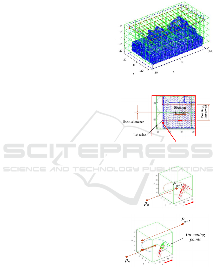
The steps of NC tool path planning are as follows:
1) Define the grid method (see [1][3]) with grid
size equal to the size of cutter diameter minus
half of the allowance (2R – 0.5* δ). See Fig. 1.
2) Start from CL in x minimum of material
𝑥
0.5∗𝛿
, and y minimum of material
𝑦
0.5∗𝛿
, and z maximum - the depth
of cut
𝑧
𝑡ℎ𝑒 𝑑𝑒𝑝𝑡ℎ 𝑜𝑓 𝑐𝑢𝑡
(see Fig. 2).
3) Move forward to the next grid and check the
condition::
If the grid is empty, the point is cutter
location
If the grid consists of points, check the
requirement to move to the other direction,
such as move-in z-direction or y-direction
(see Fig. 3). Figure 3 shows the CL when
the CC is over cut. Therefore, moving the
CL so that there is no overcut. Figure 4
depicts the tool path for one completed
step. There are some grids with the point
cloud so that CL is moving in the up
direction. Figure 5 illustrates the tool path
for one completed step in x- and y-
direction.
4) After finishing one cycle, forward-moving to
x+. If x is the maximum tool, it is then moved
into y+ and then moved backward to x-. If the
tool reaches y foremost tool moves into z-. The
process is iterative until rough cutting is
finished.
Figure 1 Grid System for Rough Cutting by Using Flat-End
Mill
Figure 2 Parameters of Cutting and Starting Point of
Cutting
(a)
(b)
Figure 3 Evaluation of Next Step of Tools (a) CC Cut Point
Cloud (Over-Cut) and (b) the Solution by Moving CC of
the Tools
Starting point
Direct NC Toolpath Generation from 3D Point Cloud Datasets
141
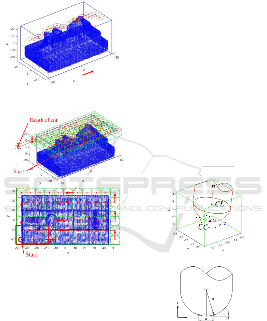
Figure 4 Tool Path for One Cycle. There is some tool cl
moving
Figure 5 Tool Path for One Cycle x and y Direction
3.3.2 Ball-end Mill Parameters
The objective of using the ball-end mill, in this case,
is to pursue the accuracy with certain tolerance and
surface smoothness with certain surface quality
(Ingeniería et al., 2016)(Yin, 2004).
The condition should be considered in the ball-
end parameter selection as the following:
Assume the vertex point is p (x
p
, y
p
, z
p
) and
the cutter's radius R. The center point of the
cutter's bottom is
𝑟
=
𝑥
,𝑦
,𝑧
, and
cutting allowance = δ.
Verify the point p is within the CC region or
not by using the following formula (see Fig.
6.11):
𝑥
𝑥
𝑦
𝑦
𝑅
Cutting direction, related to x-direction
In flat surface:
Interval= 2R
For concave and convex surface
Using interpolation
Depth of cut, related to z-axis
In net shape: t (t = tolerance)
Calculate maximum z
c
of based on the
point in CC region using the following
formula:
𝑧
𝑧
𝑅
𝑥
𝑥
𝑦
𝑦
+ t
Where t is tolerance.
Cutting interval related to y-axis direction is
using the following formula (see Fig. 2):
𝑑2
2𝑅 ℎ
ℎ
Figure 6 Ball-End Mill Position
(a) Ball and mill parameters
ASAIS 2020 - Annual Southeast Asian International Seminar
142
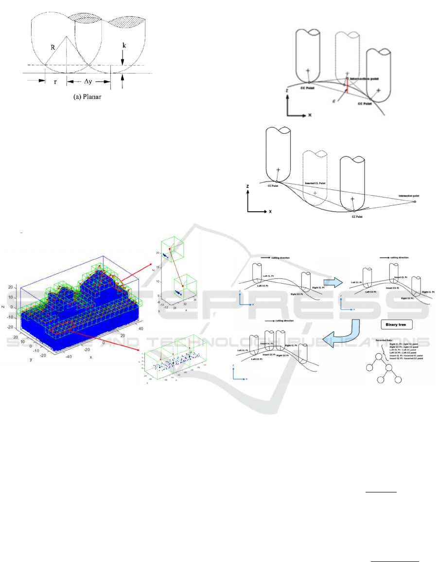
(a) Ball in interval
Figure 7 Ball-End Mill Cutting Interval (Yau & Hsu, 2009)
To define cutter location, it firstly generates a grid
in z-value maximum (for z-direction cutting) (Park,
2003). The second step is to check the tool location
(CC and CL) in each consecutive grid (forward and
backward moving). The principal of semi-finished
and finished process are equal. However, ball
diameter and interval of cutting are different as shown
in Fig. 8.
Figure 8 Ball-End Mill Path Checking
The condition of each grid in which CC and CL
are located is checked. There are two cases of grid CC
and CL condition.
- Case 1: the same z-value for the next grid, so
only check the cutter contact (CC).
- Case 2: different z-value, besides checking the
cutter contact (CC), the interpolation is
applied and paths between grids are checked..
3.3.3 Interpolation
The interpolation method (Yau & Hsu, 2009) is used
to solve the convex and concave curvature condition
in the tool's moving, as displayed in Fig. 9. Figure 10
presents the condition of overcutting in tool moving.
The solving is by generating buffer points (points
from interpolation process) to avoid over-cut. A
binary tree can be used to define the next buffer point
that created.
Figure 9 Overcut Condition in Concave and Convex
Surface (Yau & Hsu, 2009).
Figure 10 Ball-End Mill Overcut Condition and the Solving
by Using Buffer Point (Yau & Hsu, 2009).
Buffer points are generated by using interpolation
method. Figure 11 shows the interpolation method.
The principal of interpolation is using the intersection
line. Buffer point that calculated by interpolation
method are using the following equation:
𝑃
.𝑧𝑃
.𝑧
𝑃
.𝑥𝑃
.𝑥
.
.
.
.
where
𝑃
is the projection of the intersection
point to the CC line.
𝜀𝑃
.𝑧𝑃
.𝑧𝑃
.𝑧𝑃
.𝑧
𝑃
.𝑥𝑃
.𝑥
𝑃
.𝑧𝑃
.𝑧
𝑃
.𝑥𝑃
.𝑥
Direct NC Toolpath Generation from 3D Point Cloud Datasets
143
where
𝜀
is step error. If
𝜀
is greater than the
machining tolerance, a different CL (buffer point)
should be interpolated at the intersection point.
Figure 11 the Interpolation Method (Yau & Hsu, 2009).
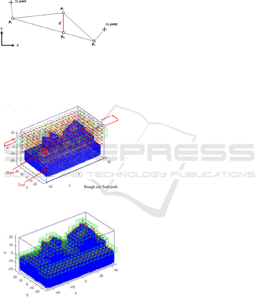
4 RESULT AND DISCUSSION
The computation CL for rough cutting and semi-
finished cutting is shown in Fig. 12 and Fig. 13,
respectively.
Figure 12 Rough Cutting CL Computation Result
Figure 13 Semi-finished Cutting CL Computation Result
In this research, the method to generate a tool path
from validated point cloud datasets registration is
described. The broader implementation can be useful
in mechanical design, die and mold, and even art and
medical. The machining tools step consists of several
stages: rough cutting, semi-finishing cutting, and
finishing cutting.
As seen in Fig. 12 and Fig. 13, the tool orientation
vectors are correctly oriented towards each point's
normal vector. This section proposes an algorithm for
generating a tool path of a 3-axis or 5-axis directly
from a point cloud dataset. However, some
shortcomings must be considered. As The grid is
created, the grid's size must be set, as shown in Fig.
1. The grid size would influence the machine
accuracy in the actual contour. The point number
filtered out within the grid affects the path precision.
If a rough grid is employed, i.e., in mm order,
numerous points can be filtered out. Consequently,
the tool path is not proper, and the feature surface to
be cut is rough.
The developed method can be applied to generate
tool paths from the subsurface relative to the
corresponding grid point cloud. Based on the point
cloud's isolation in the formed grid, the tool center
point relative to the point cloud data is determined.
The tool path between the tool center points of two
neighboring grids is obtained from the two-nodal
trajectory projection in a 2D triangular lattice. This
path is verified whether it is tangent to another point
or not. If there is a tangent point to the tool path in the
triangle's projection, it is necessary to filter it; if it
does not attain, it will go directly to the next point. 3D
distance between cutter center points in adjacent grids
is not taken into account.
If another feature form (in the form of data cloud
points) exists between two cutter center points in the
adjacent grid, that feature must be considered in
determining the tool path. The accuracy of the cutter
cuts in the two adjacent grids will also be affected. In
addition, special features such as sharp edges, sharp
elbows, sharp edges in the projection profile cannot
be recognized in the proposed algorithm. Thus, for
these cases, some algorithm modifications have to be
made.
5 CONCLUSIONS
This research discusses generating the NC-tool path
directly from point cloud data. Firstly, the machining
process and cutter used are defined. Secondly,
selecting the type of path will be used in this system.
Some parameters can be assigned to control
machining processes such as the dimension of an
object, its position and orientation, surface roughness,
workpiece material, and machining tolerance, and so
ASAIS 2020 - Annual Southeast Asian International Seminar
144

on. The other machining parameters to be considered
in the process are cutting speed, spindle speed, feed
per minute, maximum chip thickness, feed per tooth,
and some tooth of the cutter, feed per revolution, and
depth of cut, remove rate, machining time, power,
pitch and so on. Those parameters will influence the
efficiency machining and surface quality of
machining.
Thirdly, the tool path type is defined. In this case,
the iso-parametric method is selected. Fourthly, the
parameters of the tool are defined. The flat-end cutter
for coarse cutting and ball-end cutter for the semi-
finished and finished surface is confirmed in this case.
Fifthly, a tool path with selected tools parameters is
generated. In this case, the grid method is applied to
evaluate the next tool moving direction. The tool path
for rough cutting and semi-finishing cutting is
generated. By implementation into a real case, it can
be concluded that the proposed method is beneficial
to create point NC-tool path directly from point cloud
data.
REFERENCES
Chen, Y. J., & Ravani, B. (1987). Offset surface generation
and contouring in computer-aided design. Journal of
Mechanical Design, Transactions of the ASME, 109(1),
133–142. https://doi.org/10.1115/1.3258777
Chui, K. L., Yu, K. M., & Lee, T. C. (2002). Direct tool-
path generation from massive point input. Proceedings
of the Institution of Mechanical Engineers, Part B:
Journal of Engineering Manufacture, 216(2), 199–206.
https://doi.org/10.1243/0954405021519843
Ingeniería, F. De, Autónoma, U., Luis, D. S., Manuel, A.,
No, N., López, E. A. M., Lim, T. (2016). IMECE2013-
65483 A new method for the generation of tool paths for
finishing near net shape components. 1–10
Lin, R., & Koren, Y. (1996). Efficient Tool-Path Planning
for Machining Free-Form Surfaces. 118(FEBRUARY)
Liu, Y., Xia, S., & Qian, X. (2013). Direct Numerical
Control ( NC ) Path Generation : From Discrete Points
to Continuous Spline Paths. 12(September 2012), 1–12.
https://doi.org/10.1115/1.4006463
Makki, A., Tournier, C., Lartigue, C., Makki, A., Tournier,
C., Lartigue, C., & Mehdi-, C. (2011). 5-axis Direct
Machining of Rough Clouds of Points To cite this
version : https://doi.org/10.3722/cadaps.2010.591-600
Marie, J., Duc, E., Lartigue, C., & Bourdet, P. (2004). A
new format for 5-axis tool path computation , using
Bspline curves. 36, 1219–1229.
https://doi.org/10.1016/j.cad.2003.12.002
Muslimin, Zhu, J., Yoshioka, H., Tanaka, T., & Saito, Y.
(2015a). Study on plane feature extraction in
registration of laser scanning data sets for reverse
engineering. Journal of Advanced Mechanical Design,
Systems and Manufacturing, 9(5), 1–14.
https://doi.org/10.1299/jamdsm.2015jamdsm0076
Muslimin, Zhu, J., Yoshioka, H., Tanaka, T., & Saito, Y.
(2015b). The utilization of feature extraction in
registration method of laser data sets in reverse
engineering of fidelity and precision part. Proceedings
of the 8th International Conference on Leading Edge
Manufacturing in 21st Century, LEM 2015, (February
2017)
Park, S. C. (2003). Tool-path generation for Z-constant
contour machining. CAD Computer Aided Design,
35(1), 27–36. https://doi.org/10.1016/S0010-
4485(01)00173-7
Sun, Y., Page, D. L., Paik, J. K., Koschan, A., & Abidi, M.
A. (2002). Triangle mesh-based edge detection and its
application to surface segmentation and adaptive
surface smoothing. IEEE International Conference on
Image Processing, 3, 825–828.
https://doi.org/10.1109/icip.2002.1039099
Yau, H., & Hsu, C. (2009). Generating NC tool paths from
random scanned data using point-based models. 897–
907. https://doi.org/10.1007/s00170-008-1542-1
Yin, Z. (2004). Rough and finish tool-path generation for
NC machining of freeform surfaces based on a
multiresolution method. 36, 1231–1239.
https://doi.org/10.1016/j.cad.2004.01.003
Zhang, D. (2009). Adaptive NC Path Generation From
Massive Point Data With. 131(February), 1–13.
https://doi.org/10.1115/1.3010710
Zhang, Z., Savchenko, M., Hagiwara, I., & Ren, B. (2010).
3-Axis NC Tool Path Generation and Machining
Simulation for Subdivision Surface of Complex Models.
10(1), 1–9
Zou, Q., & Zhao, J. (2013). Computer-Aided Design Iso-
parametric tool-path planning for point clouds.
Computer-Aided Design, 45(11), 1459–1468.
https://doi.org/10.1016/j.cad.2013.07.001
Direct NC Toolpath Generation from 3D Point Cloud Datasets
145
