
Driveline Analysis of Electric Vehicle Conversion Performance
Fuad Zainuri
1,3
, D. A. Sumarsono
1
, M. Adhitya
1
, Rolan Siregar
1,2
Sonki Prasetya
1,3
, Ghany
Heryana
1,4
, Nazaruddin
1,5
, Widiyatmoko
3
, Iwan Susanto
3
, Rahmat Subarkah
3
, Belyamin
3
, Ihsanudin
3
1
Research Center of Advanced Vehicle (RCAVe), Universitas Indonesia, Depok 16424, Indonesia
2
Department of Mechanical Engineering, Universitas Dharma Persada, Indonesia
3
Center of Automotive, Politeknik Negeri Jakarta, Depok 16424, Indonesia
4
Department of Mechanical Engineering, STT Wastukancana, Indonesia
5
Department of Mechanical Engineering, Universitas Riau, Indonesia
Keywords: Electric Vehicle, Driveline Analysis, Center of Gravity, Conversion Performance
Abstract: Along with the development of electric vehicle in Indonesia, one of the effort from Universitas Indonesia is
developing on electric car that converted from usual car. But, after it was converted from conventional car
which named Makara Electric Vehicle 02 still need crosschecking on several aspects, especially on braking.
The author will focus on the effect of center of gravity and total mass to the braking characteristics which is
braking forces and stopping distance by doing weigh testing and after that data processing to the
characteristics that needed. The author also explained data result and compared it to the same M1 vehicle type
before it was converted. The result of the test showing that center of gravity MEV 02 start from 0,57-0,62
meter along increase in passengers, for braking force start from 4900-6200N along increase in passengers,
and for stopping distance start from 2-18m for velocity on 20 km/h, 40 km/h, and 60km/hours. Transportation
is one of the biggest sectors that contributes to pollution in cities area. This happens because of the exhaust
gas produced by the vehicles contains dangerous gases that causes air pollution. Electric vehicle is the
alternative mode of transportation that does not produce any exhaust gas at all, yet it will take a long time for
the masses to adapt to this new source of energy for the vehicle, and that was when the idea came up to convert
a conventional vehicle. Makara Electric Vehicle 02 is an electric vehicle conversion project, using Daihatsu
Ayla as the base platform, the internal combustion engine is replaced with AC Induction Motor 7.5 kW, while
all the rest of the driveline components remains the same to use the standard components. This research will
test the vehicle performance using dynamometer, calculating the resistance force working on the vehicle, and
the maximum road incline handled by the vehicle by calculating tractive effort produced by the vehicle. The
result is that the vehicle produced maximum power of 12.08 HP, with maximum torque of 86.25 Nm at 750
RPM. With used of the dyno test it is measured that the maximum vehicle speed is 46 km/hour. The
transmission mapped the powertrain RPM to work and the range of 1237-3759 RPM on first gear, 776-3527
RPM on second gear, 720-2624 RPM on third gear, 692-1989 on fourth gear, and 566-1626 RPM on fifth
gear. The maximum road incline is 22 degree of slope. When the battery condition is not in a full state of
charge, the performance of the motor dropped 29% form the maximum capabilities of the motor.
1 INTRODUCTION
The development of electric vehicle is continue
expanding in the world. The demand of electric
vehicle and the infrastructure that supporting electric
vehicle continue to expand (Zainuri et al., 2017). This
issue is getting attention from Universitas Indonesia
to always develop the electric vehicle. Universitas
Indonesia is conducting research on electric vehicle
especially conducting researching on conversion
vehicle from conventional vehicle. This thing become
research target especially on urban communities who
are matched with economic, social, and legal studies.
Electric vehicle can produce four times less
particulate and twenty times less nitrogen oxides
(Rozman et al., 2019). This advantage suitable with
Indonesia’s purpose to reducing the country’s
emission gas (Spanoudakis et al., 2019). Another
objective on this research is to prove that people can
convert conventional car into electric car according to
their budget, however, after doing the conversion,
there are many things that needed to be tested for the
Zainuri, F., Sumarsono, D., Adhitya, M., Siregar, R., Prasetya, S., Heryana, G., Nazaruddin, ., Widiyatmoko, ., Susanto, I., Subarkah, R., Belyamin, . and Ihsanudin, .
Driveline Analysis of Electric Vehicle Conversion Performance.
DOI: 10.5220/0010538100003153
In Proceedings of the 9th Annual Southeast Asian International Seminar (ASAIS 2020), pages 101-107
ISBN: 978-989-758-518-0
Copyright
c
2022 by SCITEPRESS – Science and Technology Publications, Lda. All rights reserved
101

conversion car can meet the standard for the vehicle
in general. There are still many things that need to be
tested for the conversion car that developed by
Universitas Indonesia, such as the influence of the
vehicle’s center of gravity and also the braking
characteristics of the conversion car. This research
was developed to analyze the data of center of
gravity, and braking characteristics for further
development. Air pollution in Jakarta is rapidly
increasing from year to year, based on the data
collected by the Air Quality Stations in Jakarta, it
shows that from 2016 to 2019, the air quality
considered as ‘not healthy’ has drastically increased.
One of many factors that contributes massively to this
issue is the gas exhaust produced by vehicles. This
problem is also faced by developed countries as well,
hence the focus on which to increase the use of
electric vehicle instead of internal combustion engine
(ICE) vehicle has been massively progressing
(Zainuri et al., 2017).
It would take some time for the masses to adopt
this new mode of transportation of using electric
vehicle, for the change would create some new
obstacles in the way. In the case of Indonesia,
currently electric vehicles are not sold commercially
from the manufacturers to be bought by the
customers, on which this issue challenged Universitas
Indonesia to start a research on converting
conventional ICE vehicle to electric vehicle. The
purpose of the research itself is to prove whether
converting a vehicle would be more cost-efficient.
The baseline of the vehicle that is converted is
Daihatsu Ayla with 998cc engine with 5-speed
manual transmission, converted to use AC Motor
7kW powered with lead-acid battery, but still using
the standard drivetrain configuration. The project is
named Makara Electric Vehicle 02 (MEV 02).
The main focus on this paper is to analyse whether
MEV 02 can perform well enough to be used in a real-
world scenario by considering the performance
output of the vehicle by pairing the standard
drivetrain configuration with the new powertrain of
the vehicle.
2 LITERATURE REVIEW
2.1 Electric Conventional Vehicles
An electric conversion vehicle is a vehicle designed
from a conventional vehicle with a fossil fuel engine
(internal combustion motor) replaced with an electric
motor as a propulsion with a power source from a DC
battery which is adjusted to the capacity of the motor
driven. By replacing the internal combustion motor
with an electric motor, many components are no
longer needed, such as the entire fuel system, air
filter, exhaust system and engine control unit.
However, there are also some components that can
still be utilized because they still perform the same
function, such as the transmission, clutch, and also all
drivetrain components of the vehicle (Adhitya et al.,
2018).
In converting a car into an electric vehicle, we
must know the type of car we are converting and
consider the weight of the car in order to ensure that
the electric motor that replaces the combustion motor
in the car is able to keep the car running as it should,
therefore, the power and torque that are can be
generated by an electric motor to be one of the
parameters to consider in converting. The type of
electric motor used in this electric conversion vehicle
is an AC motor 7.5 kW. In addition, because the
electric motor is powered by a battery, we also have
to consider the type of battery to be used, whether the
battery is able to provide the power needed for the
electric motor used. There are two types of batteries
commonly used in electric vehicles, namely Deep
Cycle Lead Acid and Lithium. The better type to use
is the lithium battery type, however, due to its very
high price, the conversion of the Makara Electric
Vehicle 02 is the Deep Cycle Lead Acid Battery. This
research will focus on the subject of analysis on the
power and torque generated by electric motors used
in conversion vehicles (Trovão et al., 2013).
The option to convert vehicles has been made by
several communities as well as government agencies.
Electric Vehicle of America (EVA) revealed that the
impact of converting electric vehicles includes lower
maintenance costs. Some of the advantages of
convertible electric vehicles are as follows: Recycling
of used vehicles, Reduction levels of air pollution,
Eliminating the need to replace lubricants,
Eliminating the obligation to use the system water
cooling, allowing users to perform the majority of
vehicle maintenance independently (Pamungkas et
al., 2017). The author uses power and torque as the
main variables as part of the analysis and also the
results of his research. the rate of work that occurs
because the force applied is power. If the force does
work (w), in a unit of time (∆t), the average power
due to the force exerted on that time frame, can be
made as an equation:
𝑷
𝒘
𝜟𝒕
(1)
Torque is a product of the force and distance
perpendicular to the axis of rotation. Like the above
equation, torque can be calculated by the force we get
ASAIS 2020 - Annual Southeast Asian International Seminar
102
at a certain distance, where on a rotating object, the
distance we use is the radius of the force to the
rotating axis of the object.
2.2 Gear Ratio
Gear ratios once a series of gears area unit want to
transmit power from the drive to the wheels, the gear
connected to the drive is named the motive force gear
or input gear, and therefore the gear connected to the
wheel is named the driven gear or output gear. In
general, the gear that's situated between the motive
force gear and therefore the driven g ear is named the
bum gear (Susanto et al., 2017). Gear quantitative
relation (GR) is that the quantitative relation of teeth
within the output gear (connected to the wheel) to the
teeth within the input gear (connected to the drive or
motor). The gear quantitative relation is that the
description of the quantitative relation of the output
force to the input force (Walker et al., 2017). Thus,
we are able to multiply the drive shaft force (input)
by the gear quantitative relation to seek out the force
at the shaft (output).
Table 1. Vehicle gear transmission ratio
Gear Ratio
I
3,417
Gear Ratio I
I
1,960
Gear Ratio II
I
1,250
Gear Ratio IV
0,865
Gear Ratio V
0,707
Gear Ratio Revers
r
3,143
F
inal Gear Ratio
4,643
Tires Dimention
155/80 R13
For the needs of the main electric motor (bus
driving) is calculated by analyzing the vehicle
traction force. The traction force needed to move a
vehicle is influenced by several drag forces that work
when the vehicle is moving which is illustrated by the
following equation:
𝐹𝑚 𝑎𝑅
𝑅
𝑅𝑔 (2)
Where: F is the traction force, m is the mass of the
vehicle, R
a
is the aerodynamic drag force, R
rl
is the
friction force, a is the acceleration of the vehicle, R
g
is the gravitational force arising from elevation
(Morozov et al., 2016).
In the vehicle performance analysis, only uphill
operations are considered. This grading style is
usually called gradation resistance from Figure 2.5,
To simplify calculations, the street angle, α, is
usually replaced with the grade value when the street
corner is small. As shown in Figure 2.5, a class is
defined as:
When road corners are small, roadblocks can be
simplified.
𝚤
tan𝛼sin𝛼 (3)
2.3 Electric Motor
Based on the business concept, electric power is the
amount of effort in moving the charge in units of time
or the amount of electrical energy per second. The
formulation is written as follows [16].
𝑊𝑉.𝐼.𝑡 (4)
Where: V is Voltage (Volt), I is Current
(Amperes), t is Time (Second) W is Energy (Joule), t
is Time (Second)
Then:
𝑃
𝑉.𝐼.𝑃
(5)
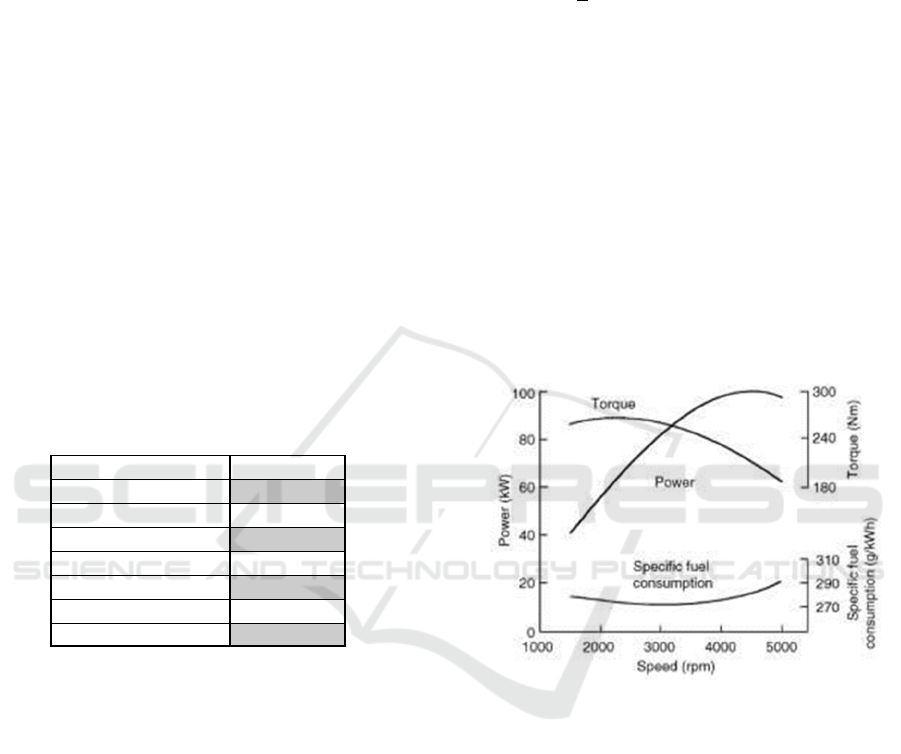
Figure 1. Types of gas engine characters (Wu et al.,
2015). Internal combustion engines have a relatively flat
(compared to ideal) torsion speed profile, as shown in
Figure 1.
As a result, multi gear transmission is usually
used to modify it, as shown in Figure 3.a. An electric
motor, however, usually has a much closer to ideal
speed-torque characteristic, as shown in Figure 3.b.
In general, electric motors start at zero speed. As it
increases to basic velocity, the voltage increases to its
rated value while the flux remains constant (Zainuri
et al., 2021).
Driveline Analysis of Electric Vehicle Conversion Performance
103
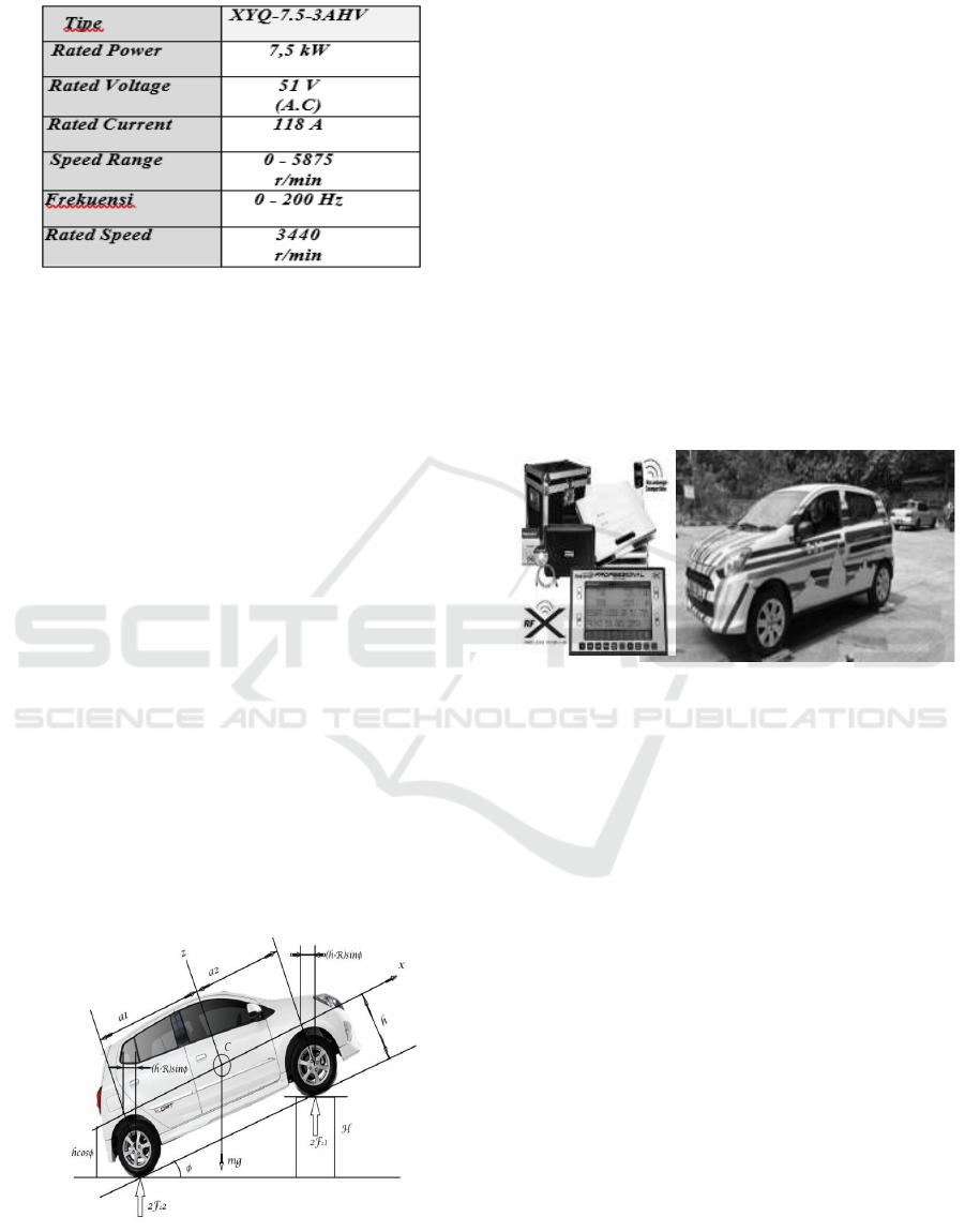
Table 2. Three-phase AC motor specifications
3 RESEARCH METHOD
From the previous description that in order to achieve
the research objectives by conducting drivetrain
testing on electric conversion vehicles to obtain 2
optimal gearshift combinations, several stages of
implementation were carried out, namely:
Preparation of Material Specifications, Preparation of
Tool Specifications, Analysis Methods, Processing
Time, Testing Standards
In this research, the data were taken by doing a
weighing test. The object of this research is M1 type
vehicle which named Makara Electric Vehicle 02 that
converted from conventional car. Weight of test has
purpose to obtain center of gravity which will be
processed further to obtain braking force and also the
stopping distance. The braking characteristics which
are braking force and stopping distance obtained by
doing some formula calculation. Data was collected
for conversion car and conversion base vehicle. This
method referring to government policies that usually
applied (Lei et al., 2019) and for the stopping distance
using policies that published by Ministry of
Transportation (Zainuri et al., 2021).
Figure 2. Freebody Diagram of Vehicle
The calculation for center of gravity collected by
figuring out the free body diagram first then insert the
result to the equation (Ahssan et al., 2018) that writer
got from another references.
When collecting data using PQA, it can be done
in the condition of the vehicle being measured in
place or in running conditions so that it is more
practical in operation. Make sure the circuit is
installed correctly so that the validity of the data can
be accounted for.
This research aims to give a concluded result of
measuring whether or not the drivetrain can deliver
the performance needed for a real-world usage
scenario. To measure the performance output of the
vehicle, this research focuses more on experiment to
collect the data of the vehicle power output by using
a chassis dynamometer then, to simulate the real-
world scenario by calculating the resistance force
acting on the vehicle.
Figure 3. Installation of tools when testing scales
4 RESULT AND DISCUSSION
From the previous description that in order to achieve
the research objectives by conducting drivetrain
testing on electric conversion vehicles to obtain 2
optimal gearshift combinations, several stages of
implementation were carried out, namely:
Preparation of Material Specifications, Preparation of
Tool Specifications, Analysis Methods, Processing
Time, Testing Standards
1. Power Train Characteristic
Based on the data collected from the
dynamometer, we calculate those data measured from
the hub resulted in the torque and power produced by
the powertrain. From the data collected at 4
th
gear, the
torque reached peak number by 94 Nm and the peak
power is 13 HP. By using statistic approximation of
third order polynomial, we could map the graph of the
performance characteristic of the motor.
ASAIS 2020 - Annual Southeast Asian International Seminar
104
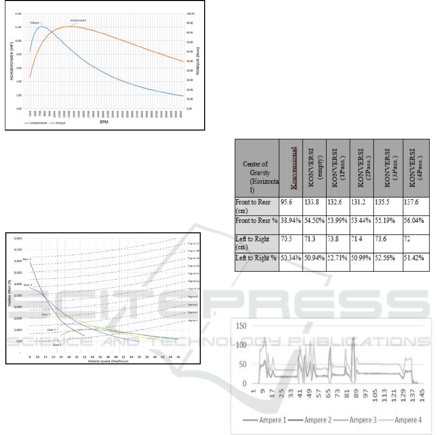
Figure 4. Powertrain characteristic
The tractive effort value is used to measure the
capability of the vehicle to withstand the resistance
force acting on the vehicle. On this experiment we
simulate force by combining all the three resistance
forces with the variance of speed the vehicle travels
and the road inclination.
Figure 5. Tractive Effort vs Resistance Force
As shown in Fig. 5 we could determine the gear
need to be used to counter the varying resistance
force by road inclination. We could also determine
the maximum vehicle speed of each gear used by the
vehicle on which it is 46 km/h. Indonesian Toll Road
regulated that the minimum speed vehicle needs to
travel is 60 km/h (Adhitya et al., 2018) on which
MEV 02 haven’t pass. By referencing to the
Indonesian National Standard of city roads
inclination geometry, it is mandated that the
inclination can’t pass 8% (Trovão et al., 2013), based
on the result MEV 02 already passed the standard.
2.
Centre of Gravity (COG)
In the implementation of this research carried out
by measuring the weight of the vehicle on each
wheel as a fulcrum by comparing the various
conditions of the different variables, both the
vehicle variable and the additional passenger
variable. 802.5 kg to 1011 kg in electric conversion
vehicles (after the addition of batteries and
motorbikes) means that there is an additional
weight of 208.5 kg with details as the addition of
the total weight of each wheel. Furthermore, in
electric conversion vehicles simulated with the
addition of passengers from the first passenger (78
kg), second (74kg), third (69 kg) and fourth
passenger (54.5) which are respectively distributed
to each part of the wheel.
Table 4. Calculation results of COG length and width
The following is one of the measurements with
PQA when operating the vehicle in a condition
without tires on the wheels
Figure 6. 3-Phase Motor RST Ampere Graph
The following are the results of measuring the
voltage and amperage of a 3-phase AC motor where
when the measurement uses the Power Quality
Analyzer (PQA), the measurement is done by running
the vehicle without a load by lifting the front wheel
and varying the rotation of gear shifting 1 to 4 with
maximum speed as following:
• The maximum speed of 1st gear is 20 km / hr
• The maximum speed of 2nd gear is 40 km / h
• The maximu m speed of 3rd gear is 60 km / h
• The maximu m speed of 4th gear is 80 km / h
Driveline Analysis of Electric Vehicle Conversion Performance
105
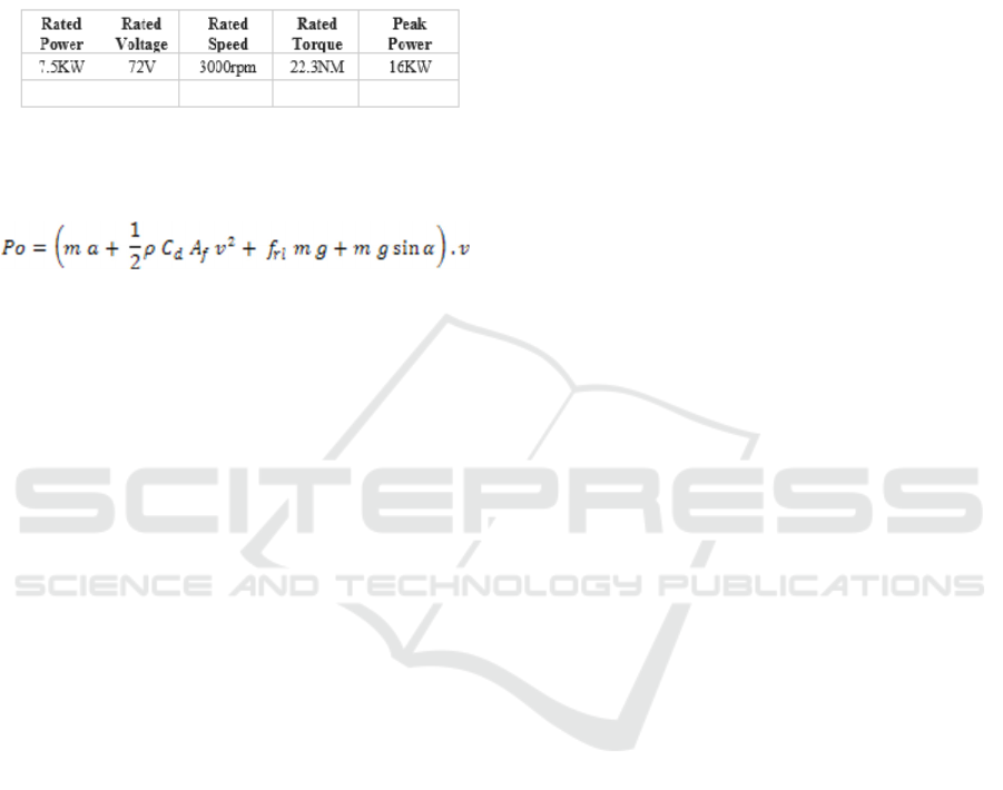
From these results, the measurement results of the
current and voltage on the 3-phase motor (attached)
are obtained and when the displacement conditions
occur a very high amperage spike, this if it occurs
continuously will result in the ability of the battery to
run out quickly.
Spesification for Inverter:
Theoretically, the vehicle will have the following
torque and power characteristics:
In light of the means above, in this examination,
the motor was supplanted with a 3-stage AC electric
engine, in addition to 6 batteries as a force source,
which the Charging cycle was done on 6 batteries
with a limit of 150 Ah and 12 Volt DC (the most
extreme voltage was 72 Volt DC. ) which is
introduced in arrangement is completed at a lingering
voltage state of 65 Volts (80%) did for 3 hours to have
the option to get the limit together to 100% of 72 Volt
DC examples and phases of charging. From Figure
4.1, we can know how the charging interaction that
happens in the battery, where when the charging cycle
increments around 7 volts from 65 to 72 volts stable,
it requires around 3 hours with a direct pattern.
When seen from the limit of the battery 150 AH
times 6 pieces and the limit of its utilization with an
engine heap of 118 A, it very well may be determined
that its utilization is equipped for turning the engine
as long as 7 hours of activity with stable conditions,
but since there are a few factors that make this
capacity not satisfied, including: vehicle load, the
course of the vehicle so it should be changed both
straight all over and slowing down because of
hindrances this condition powers the genuine
capacity to be acquired around 4 hours of activity.
DC-DC Converter introduced on the change vehicle
as demonstrated in Figure 37 is an instrument that
capacities to charge the battery emotionally
supportive network by decreasing the voltage from 72
volts to 12 volts. This supporting battery capacities to
supply capacity to the vehicle's actualize the two
wipers, horns and even the main thing is the inventory
to the slowing mechanism.
In the execution of this exploration completed by
estimating the heaviness of the vehicle on each wheel
as a support by looking at the different states of the
various factors, both the vehicle variable and the extra
traveler variable. 802.5 kg to 1011 kg in electric
transformation vehicles (after the option of batteries
and motorbikes) implies that there is an extra weight
of 208.5 kg with subtleties as the expansion of the
complete load of each wheel. Moreover, in electric
transformation vehicles recreated with the expansion
of travelers from the primary traveler (78 kg), second
(74kg), third (69 kg) and fourth traveler (54.5) which
are individually dispersed to each piece of the wheel.
The extra weight brought about a huge change
according to changes in the focal point of gravity
which brought about the deliberate and determined
focus of gravity in great condition in light of the fact
that the worth had changed from 38.94% (front to
back) to 54.50% and was in the vehicle since it was
getting lower, the center, the better. Similarly, the
change from 50.34% to 50.95% (from left to right) so
the lower the focal point of the vehicle, the impact
will be felt when the vehicle is bowed at a turn or
move.
5 CONCLUSIONS
From the results of the research and analysis
presented, the following conclusions can be drawn:
1. Conventional vehicle conversion (power 65 HP /
6000 RPM and torque of 86 Nm / 3600 RPM) is
one solution considering the large population of
conventional vehicles and the possibility of
expensive electric vehicles being the background
for the research on the conversion of these
vehicles into electric vehicles.
2. Charging the battery is done with a fast process
with a duration of about 3 hours for a charge of
5-7 volts (65-72 volts) with a battery capacity of
150 AH times 6 pieces and the capacity of its use
with a motor load of 118 A real capability
obtained about 4 hours operation.
3. The results of the calculation of the power and
torque generated by the motor, the maximum
power of the motor is 61.13 kW at 5000 rpm
motor rotation and the resulting torque is 116.75.
4. Selection of the transmission ratio that is very
suitable for use in two-speed transmissions is the
transmission ratio 1.96 for 2nd gear and 1.25
transmission ratio for 3rd gear based on
calculations and from the results of analysis and
calculations. Between 2nd and 3rd gears, the
value of torque and power to speed optimization
has the highest value so that the vehicle is only
capable of traveling at 65.30 km / h at two speeds
ASAIS 2020 - Annual Southeast Asian International Seminar
106

and the vehicle is also capable of traveling at
49.98 km / h in second gear.
ACKNOWLEDGMENTS
This research was funded by Ristek BRIN Research
Grants PD and PTUPT. Many thanks for all parties at
the DRPM Universitas Indonesia and UP2M
Politeknik Negeri Jakarta which provided facilities
and opportunities to this research. The authors thank
the anonymous referees for their valuable
suggestions, which led to the improvement of the
manuscript.
REFERENCES
Adhitya, M., (2018). Devepolment a New Model of
Synchromesh Mechanism to optimization Manual
Transmission' s Electric Vehicle. Pp. 2018.
Ahssan, M. R., Ektesabi, M. M., and Gorji, S.A., (2018).
Electric Vehicle with Multi-Speed Transmission: A
Review on Performances and Complexities. SAE Int. J.
Altern. Powertrains, vol. 7, no. 2. doi: 10.4271/08- 07-
02-0011.
Lei, Y. et al., (2019). Control strategy of automated manual
transmission based on active synchronisation of driving
motor in electric bus. Adv. Mech. Eng., vol. 11, no. 4,
pp. 1-17. doi: 10.1177/1687814019846734.
Morozov, A., Zou, Saman, T., M., Mousavi, R., Angeles,
J., and Boulet, B., (2016). Design of a Modular Swift -
shift Multi-speed Transmission with Double Dual
Clutches for Electric Vehicles. World Electr. Veh. J.,
vol. 8, Pp. 1-12.
Pamungkas, P. M., Adhitya, M., and Sumarsono, D. A.,
(2017). Design and Analysis of Tubular Space-Frame
Chassis with Impact Absorbers on Sports Car. Pp.
20923-20928, doi:10.15680/IJIRSET.2017.0610193.
Rozman, M. et al., (2019). Smart Wireless Power
Transmission System for Autonomous EV Charging.
IEEE Access, vol. 7, pp. 112240-112248. doi:
10.1109/access.2019.2912931.
Spanoudakis, P., Tsourveloudis, N. C., Doitsidis, L., and
Karapidakis, E.S., (2019). Experimental research of
transmissions on electric vehicles' energy consumption.
Energies, vol. 12, no. 3, pp. 1-15. doi:
10.3390/en12030388.
Susanto, N., Purwaningsih, R., and Baharullah, I. A.,
(2017). Analisa Pengaruh Transmisi Mobil Manual di
hadapan pengemudi pemula," J. Tek. Ind., vol. 12, no.
3.
Trovão, J. P., Pereirinha, P. G., Jorge, H. M., and Antunes,
C. H., (2013). A multi-level energy management
system for multi-source electric vehicles - An
integrated rule-based meta-heuristic approach. Appl.
Energy, vol. 105, Pp. 304-318. doi:
10.1016/j.apenergy.2012.12.081.
Walker, P., Zhu, B., and Zhang, N., (2017). Powertrain
dynamics and control of a twospeed dual clutch
transmission for electric vehicles," Mech. Syst. Signal
Process., vol. 85, Pp. 1-15. doi:
10.1016/j.ymssp.2016.07.043.
Wu, G., Zhang, X., and Dong, Z., (2015). Powertrain
architectures of electrified vehicles: Review,
classification and comparison," J. Franklin Inst., vol.
352, no. 2, Pp. 425-448. doi:
10.1016/j.jfranklin.2014.04.018.
Zainuri, F., Sumarsono, D. A., Adhitya, M., and Siregar,
R., (2017). Design of Synchromesh Mechanism to
Optimization Manual Transmission's Electric Vehicle.
AIP publishing Conf. Pros., vol. 020031. doi:
10.1063/1.4978104.
Zainuri, F., Sumarsono, D. A., Adhitya, M., Siregar, R.,
Prasetya, S., Heryana, G., Nazaruddin, Subarkah, R.,
Widiyatmoko. (2021). Performance Analysis of Power
Train Electric Vehicle Transmission Two Speed with
Reverse Engineering Method. JMERD, vol. 43 no 04,
pp. 417-427.
Zainuri, F., Sumarsono, D. A., Adhitya, M., Siregar, R.,
Prasetya, S., Heryana, G., Nazaruddin, Susanto, I.,
Subarkah, R., and Ihsanudin., (2021). Analysis and
Optimization of Electric Vehicle Conversion
Performance, JMERD, vol.44 no. 03,pp. 128-137.
Driveline Analysis of Electric Vehicle Conversion Performance
107
