
DOE Analysis and Improvement of a Rotor Design for OWC Radial
Impulse Turbines
Khalid Elatife
*1
and Abdelatif El Marjani
**1
1
Labo. de Turbomachines, Ecole Mohammadia d’Ingénieurs, Université Mohammed V
B.P. 765 Agdal, Rabat, Maroc
**
Corresponding author: Fax: +212 5 37 77 88 53 Email: elmarjani@emi.ac.ma
Keywords: Wave energy, OWC devices, impulse radial turbine, rotor blade optimization, design of experiment, turbine
efficiency.
Abstract: Wave energy exploitation is of great interests nowadays due to its sustainability, reliability and large potential.
A brief analyze of wave energy potential in the Moroccan coastline with an idea on the importance of
implementing WEC, and presents secondly an implementation of the experimental design method to optimize
the self-rectifying impulse radial turbine in the OWC devices, which is the most exploited system, for wave
energy extraction are presented in this paper. A novel design with circular arcs and straight lines for the rotor
blade will be presented. A first work of optimizing the rotor blade design in terms of the turbine efficiency by
the design of experiment method has been done. The work has done as outputs two optimal rotor blade
profiles, one for the exhalation and the other for the inhalation modes. As a second part of the work, optimizing
the solidities of the guide vanes and of the rotor by implementing a second design of experiment will be
established.
NOMENCLATURE
)(
2
1
22
RR
A
u
P
C
: Input coefficient
RRRR
T
rAu
P
C
)(
2
1
22
: Torque coefficient
P
: Total pressure drop
R
r
: Mean radius
R
A
: Characteristic area
: Air density
RR
wru
: Circumferential velocity at
R
r
br
q
R
R
2
: Mean radial velocity
q
: Flow rate
b
: Rotor blade height
: Turbine efficiency
r
s
: Radius of the suction side of the blade rotor
r
p
: Radius of the pressure side of the blade rotor
l
r
: Blade chord*
t: Inter-distance between centre of the two circular
arcs of the blade rotor
β*: Geometrical angle in the leading and trailing
edges of the blade rotor
α: Guide vane incidence angle
: Flow coefficient
1 INTRODUCTION
One of the most abundant resources of renewable
energy in the world is the ocean energy. In the world,
its potential is estimated of about 8 000-80 000
TWh/year (AEA Energy & Environment on the
behalf of Sustainable Energy Ireland for the IEA’s
Implementing Agreement on Ocean Energy Systems,
2006), and on the Moroccan coasts to 25-30 kW/m,
which is for about 700 to 900 TWh/year (ELATIFE
& EL MARJANI, 2014). It encloses energy resources
such as: wave energy, tidal energy, thermal energy
and marine currents energy. In the R&D field, great
efforts were made during the last decades, in order to
harvesting this huge energy for covering the
continuous growing of the human energy needs. For
the wave energy extraction field for instance, several
energy system converters were introduced, especially
the oscillating Water Column (OWC) which is the
most used design for its low cost of installation and
the simplicity of its maintenance.
The OWC devices are composed of three parts: air
chamber, air turbine and electrical generator. The first
component is used to convert wave energy to
pneumatic one; the second one is used to convert this
pneumatic energy to mechanical energy which is
finally converted to electrical energy in the generator.
Several OWC devices are built in 1990s and are still
working, such as the Picot plant in Azores, Portugal
(FALCAO, 2000) and the LIMPET plant in Islay,
Scotland (Heath &Whitakker & Boake, 2000).
The air turbine equipping the OWC device should
rotate in one direction despite of the bidirectional air
flow over it due to the water oscillating inside the air
chamber. The first turbines used in the OWC
prototypes are the Wells type turbines. However,
through exploitation of this turbine, some
disadvantages have been encountered (Falcao, 2003),
such as: high efficiency in a narrow range of flow
rates, poor starting characteristics, high speed
operation, high noise level, high periodical axial
thrust and finally the crucial problem of stall. An
alternative type turbine was proposed by I.A.
Babinstev in order to overcome these drawbacks
(Babinstev, 1975), which is impulse type turbine.
The axial and the radial are the two configuration
types of impulse turbine that have been introduced.
According to research investigations, it has been
found that the radial impulse turbine has some
advantages compared to the axial one in terms of low
manufacturing cost, high torque due to the radial
configuration and the absence of the oscillating axial
thrust. However, a main problem of the large
aerodynamic losses due to the important incidence air
flow angle in the inner and outer guide vanes can be
presented for the impulse turbine. It is due to the
required symmetry of the two rows of guide vanes
because of the bidirectional movement of the air flow.
In order to optimise the impulse turbine
performances, several investigation researches were
elaborated since the early 1990s. In the last decade,
many improvements in turbine geometries were
proposed. According to investigation results of
reference (Pereiras & Castro & El marjani &
Rodriguez, 2011), improved performances can be
obtained in both operating modes (inhalation and
exhalation) by modifying the aerodynamic design of
the inner guide vanes in the radial impulse turbine. A
model of his improved turbine has been manufactured
and installed in the EMI’ Turbomachinery Laboratory
for experimental tests. An alternative design of the
axial impulse turbine has been introduced (Takao &
Setogushi, 2012) in which the solution consists of
coupling two turbines installed in a twin
configuration for optimizing the efficiency in
inhalation and in exhalation operating modes. Tests
have revealed significant improvement in the
efficiency. a varying radius model of the axial
impulse turbine is another design that has been also
considered in order to reduce the aerodynamic losses
and consequently increase the efficiency (Natanzi &
Teixeira & Laird, 2011). Recently, a novel bi-radial
turbine has been proposed for which a notable
increasing efficiency (close to 80 %) has been reached
(Falcao & Gato & Nunes, 2013a; Falcao & Gato &
Nunes, 2013b).
In this paper, we will analyse the wave energy
potential in the Moroccan coastline that can gives an
idea on the importance of implementing WEC, and
presenting a numerical experimental design method
with ANSYS FLUENT for optimizing the impulse
radial turbine in terms of some design parameters. A
new rotor blade design has been proposed with two
circular arcs that have dependent radii and two
straight lines in the leading and trailing edges. This
work has consisted on optimizing the blade rotor
design by drawing up a numerical experimental
design of four factors; the radius of the suction side,
the chord, the inter-distance between centre of the two
circular arcs and the geometrical angle in the leading
and trailing edges of the blade rotor. Two optimal
rotor blade profiles have been found, one for the
exhalation and the other for the inhalation modes. The
future research work will consist on optimizing the
solidities of the inner and outer guide vanes and of the
rotor by implementing a second design of experiment.
2 WAVE ENERGY IN THE
MOROCCAN COASTLINE
Over the last years, a set of fixed, floating and
submerged wave energy converters has been installed
in order to estimate the wave energy potential. Each
device is regarded to extract wave energy over a range
of operating conditions in terms of wave period and
height.
To justify the interest of implementing wave
energy converters in the coastlines of any country, it
is required to analyse its wave power.
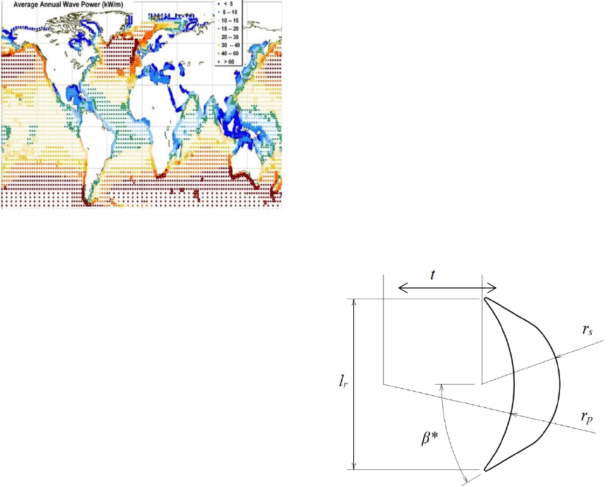
Figure 1: Worldwide average wave power potential (kW/m)
(Lagune & Benalia & Benbouzid, 2010)
Figure 1 shows the distribution of the wave energy
potential in the world. It can be noticed from this
figure that the average annual wave power in the
Moroccan coasts is estimated to be between 25 and 30
kW/m.
According to the previous graphs, it can be
noticed that the implementation of the wave energy
converters in the Moroccan coastlines will be highly
profitable in terms of the amount of energy that can
be extracted from wave. The Moroccan coastline
energy potential is estimated for the length of 3400
km to 900 TWh/year.
One of the most studied wave energy converters
is the OWC device, which is due to its simplicity. The
OWC devices are composed of three parts: air
chamber, air turbine and electrical generator. The first
component is used to convert wave energy to
pneumatic one, and the second from the pneumatic to
mechanical one, and finally from mechanical to
electrical energy in an electrical generator. As a result,
the global efficiency will depend on the efficiency at
each phase of this energy conversion chain. For high
OWC performances, great attention should be paid in
the design of the turbine (El marjani & Castro &
Rodriguez & Parra Santos, 2008).
For this reason, our present work consists on
optimizing the impulse radial turbine efficiency,
especially the rotor blade design, for a better
harvesting of the huge wave energy in the Moroccan
coastlines.
3 A NEW ROTOR BLADE
DESIGN OF IMPULSE
TURBINE
From the literature, several aerodynamic problems
have been investigated for the self-rectifying impulse
turbine, like the flow separation at the outlet guide
vanes (Setoguchi & Takao & Kinoue & Kaneko &
Santhakumar & Inoue, 1999). Another problem that
leads to energy losses is the separation of the
boundary layer in the suction side of the rotor blade.
In order to minimize theses energy losses, a new rotor
blade design with circular arcs in the pressure and
suction sides has been elaborated. The Figure 2 shows
the new blade geometry.
Figure 2: New blade rotor geometry
4 EXPERIMENTAL DESIGN FOR
OPTIMIZING THE ROTOR
BLADE
Method Approach. Experimental design is an
optimization method that uses experimental testing
by ordered sequence called experimental design of an
experiment, each to acquire new knowledge by
controlling one or more input parameters to obtain
results validating a model with a good economy
(number of trials as low as possible, for example).
For our case, a 2D numerical experimental design
has been used for the radial impulse turbine and
considering as the input parameters the geometrical
characteristics of the blade rotor. The other
parameters have been fixed and based on the values
of the reference (Setoguchi & Santhakumar & Takao
& Kanako, 2002). Four variables parameters have
been considered; the radius of the suction side rs, the
blade chord lr, the inter-distance between centre of
the two circular arcs t, and the geometrical angle in
the leading and trailing edges of the blade rotor β*.
The guide vane incidence angle α has been chosen
with respect of the triangle velocity of the air flow.
The output result considered is the turbine efficiency.
The radius of the pressure side rp and of the suction
side rs are joined by a Brilling rule that found in the
literature:
ps
rr .
3
5
(1)
The mathematical model for this case of study is
as follows:
= a
1
+ a
2
.rs + a
3
.lr + a
4
. β* + a
5
.t (2)
Each input parameter has two levels of variation,
as presented in the Table 4:
Table 1: Dimensionless values of the four input parameters
for the two levels (with respect to the value: 55 mm)
Level r
s
(mm)
l
r
(mm)
β* t (mm)
-1 0.436 0.818 25° 0.545
1 0.545 1 35° 0.6
Instead of using an exhaustive experimental
design which needs 24 tests, it is interesting to
use an optimized experimental design (Lundstedt,
1998) that needs lesser tests, for example the matrix
of Hadamard that needs just 8 tests for this case. This
matrix is presented in the Table 2.
Table 2: Hadamard matrix for four parameters and two
levels
N°
r
s
l
r
β* t
1 1 1 1 -1
2 -1 1 1 1
3 -1 -1 1 1
4 1 -1 -1 1
5 -1 1 -1 -1
6 1 -1 1 -1
7 1 1 -1 1
8 -1 -1 -1 -1
The values of ai, i=1,…,5 , for the two phases;
inhalation and exhalation, have been obtained in
matrix form as follows:
[
] = [H] . [a] (3)
With: [
]t=[
1,…,
8] ; [a]t= [a1,…, a5] ; [H] is
the Hadamard matrix for a dimension of 8 × 5 with
the first column is a unitary column.
The numerical tests have been performed with
ANSYS FLUENT for the rotor torque extraction for
different flow coefficient
. The standard k-ε model
has been used to model the flow turbulence. A
segregated solver has been used to solve the coupled
conservation equations of mass, momentum and
energy. The algorithm of SIMPLEC is adopted to
perform the pressure-velocity coupling
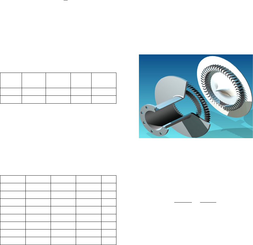
The turbine is composed of a rotating part, the
rotor, and a fixed part, the stator, Figure 3. In order to
manage the relative movement between the fixing and
the moving part of the turbine, the sliding mesh
technique is used. The boundary conditions adopted
is a uniform total pressure at the inlet and a uniform
static pressure at the flow outlet. The condition of
non-slip is adopted for all the walls.
Figure 3: Rotor and stator of radial impulse turbine
(Pereiras & Castro & El marjani & Rodriguez, 2011)
Results and Discussion. The turbine efficiency η is
expressed in terms of the torque coefficient CT, input
coefficient CA and the flow coefficient
as
mentioned above:
..
.
0
A
T
C
C
Qp
wT
(4)
With the rotational speed of the rotor
w
chosen
is 234 rpm.
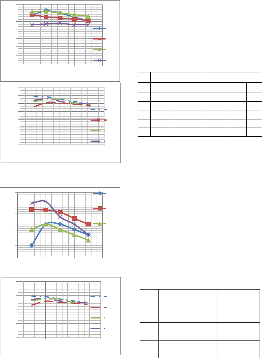
The results of the eight tests by numerical
simulation in both two phases; exhalation and
inhalation are plotted in Figures 4 and 5,
=f (
).
a)
b)
Figure 4-a) and 4-b): Turbine efficiency for exhalation
mode for the eight tests
a)
b)
Figure 5-a) and 5-b): Turbine efficiency for inhalation mode
for the eight tests
For the rest of the work, three flow coefficients
have been chosen to optimize the turbine efficiency
for both phases; exhalation and inhalation, which are:
0.5, 1.5 and 2.5.
The values of the coefficients ai, i=1,…,5 are
presented in the two Tables 3 for exhalation and
inhalation modes.
Table 3: The coefficients a
i
, i=1,..,5 for exhalation and
inhalation
Inhalation Exhalation
-0.5 -1.5 -2.5 0.5 1.5 2.5
a1 58.35 54.87 50.25 59.54 59.74 54.6
a2 24 24 24 24 24 24
a3 55 55 55 55 45 45
a4 25 25 25 35 35 35
a5 33 33 30 33 30 30
5 OPTIMIZATION OF BLADE
ROTOR GEOMETRY
In order to determine the combination (s) of the four
input parameters that maximize the turbine efficiency
for the two phases of functioning, an optimizing
program has been elaborated with MATLAB.
The objective function is the equation (2) and the
variable inputs are the input parameters of the design
of experiment. Their variation is inside their two
levels with a step of 1 mm for rs, lr and t, and 2° for
β*.
The optimal combination for the three flow
coefficient values in both phases is presented in the
Table 4 below:
Table 4: Dimensionless values of optimal combinations for
the three flow coefficient values for exhalation and
inhalation modes
Exhalation
(r
s
;l
r
;β*; t)
Inhalation
(r
s
;l
r
;β*; t)
=0.5
(0.436;1;35°;0.6) (0.436
; 1 ;
25° ; 0.6)
=1.5
(0.436
; 0.818 ; 35°
; 0.545)
(0.436
; 1 ;
25° ; 0.6)
=2.5
(0.436
; 0.818 ; 35°
; 0.545)
(0.436
; 1 ;
25° ; 0.6)
It can be noticed that there are two optimal
combinations for exhalation; C1(0.436;1;35°;0.6) and
0
10
20
30
40
50
60
70
0123
Efficiency(%)
Flowcoefficient
Test1
Test2
Test3
Test4
0
10
20
30
40
50
60
70
0123
Efficiency(%)
Flowcoefficient
Test5
Test6
Test7
Test8
44
46
48
50
52
54
56
0123
Efficiency(%)
Flowcoefficient
Test
1
Test
2
Test
3
0
20
40
60
80
0123
Efficiency(%)
Flowcoefficient
Test5
Test6
Test7
Test8

C2(0.436 ; 0.818 ; 35° ; 0.545), and one for
inhalation; C3= (0.436 ; 1 ; 25° ; 0.6). The
combination C3 is chosen for optimizing the turbine
efficiency in inhalation mode, and for choosing one
of the two combinations C1 and C2 that optimizes the
efficiency for the exhalation mode, new simulation
tests has been done for the two combinations in
exhalation mode in order to choose the one which
maximise the some of the three efficiencies for
different flow coefficients. The Table 5 represent the
values of efficiencies for the combinations C1 and
C2.
Table 5: Turbine efficiency for the combinations C1 and C2
in exhalation mode
C1 C2
0.5 58% 62%
1.5 54% 58.5%
2.5 51.2% 52.7%
From the numerical tests results, the combination
C2 for the exhalation mode has the maximum
efficiency in all the three flow coefficients. So C2 is
the optimal combination for the exhalation mode.
The Table 6 represent a recapitulation of the
optimal combinations for exhalation and inhalation
modes.
Table 6: Dimensionless values of optimal combinations for
exhalation and inhalation modes
Mode (r
s
;l
r
;β*; t)
Exhalation (0.436 ; 0.818 ; 35° ; 0.545)
Inhalation (0.436 ; 1 ; 25° ; 0.6)
The optimized rotor profiles for the two phases;
exhalation and inhalation are presented in Figures 6
and 7.
Figure 6: Optimized rotor
blade profile for
exhalation
Figure 7: Optimized rotor
blade profile for inhalation
6 CONCLUSION
In this paper, we have applied the design of
experiemnt method to optimize the rotor blade
geometry in order to maximise the turbine efficiency.
The tests have been done by 2D numerical simulation
with ANSYS FLUENT for time exigencies. Four
variables parameters has been chosen as inputs; the
radius of the suction side, the blade chord, the inter-
distance between centre of the two circular arcs, and
the geometrical angle in the leading and trailing edges
of the blade rotor, and one as output; the turbine
efficiency. The other parameters have been fixed.
An optimizing program has been elaborated with
MATLAB and two combinations of the inputs
parameters that maximize the output parameter; the
turbine efficiency, in exhalation and inhalation modes
have been found; (rs ;lr ;β*; t) = (0.436 ; 0.818 ; 35° ;
0.545) for exhalation and (rs ;lr ;β*; t) = (0.436 ; 1 ;
25° ; 0.6) for inhalation.
For the future work, a second design of
experiment will be elaborated for optimizing the
guide vanes and the rotor solidities, in order to find
an optimal design of the turbine in exhalation and
inhalation modes.
REFERENCES
“Review and analysis of ocean energy systems
development and supporting policies”, A report by AEA
Energy & Environment on the behalf of Sustainable
Energy Ireland for the IEA’s Implementing Agreement
on Ocean Energy Systems, 28th June 2006.
K. Elatife, A. El Marjani, “Design Evolution of Self-
Rectifying Air Turbine for OWC Devices”, 1er
Colloque franco-marocain sur les énergies nouvelles et
renouvelables, October 2014.
Falcão AF de O. The shoreline OWC wave power plant at
the Azores. In: Proc. 4th European wave energy
conference. Denmark: Aalborg; 2000.
Heath T, Whittaker TJT, Boake CB. The design,
construction and operation of the LIMPET wave energy
converter (Islay, Scotland). In: Proc. 4th European
wave energy conference. Denmark: Aalborg; 2000.
Falcão AF de O. R&D Requirements for Fixed Devices.
WaveNet, Section C. Results Report from the work of
the European Thematic Network on Wave Energy,
March 2003. European Community, ERK5-CT-1999-
20001, 2000–2003. p. 141–74 / http://www.wave-
energy.net/LibraryS.
Babintsev IA. Apparatus for converting sea wave energy
into electrical energy, U.S. Patent No. 3922739, 1975.
Pereiras B, Castro F, El Marjani A, Rodriguez MA. “An
improved radial impulse turbine for OWC”. Renew
Energy 2011; 36:1477-84.
M. Takao and T. Setoguchi, Review article, “Air turbines
for wave energy conversion”, International Journal of
Rotating Machinery, 2012.
Natanzi S, Teixeira JA, Laird G. “A novel high-efficiency
impulse turbine for use in oscillating water column
devices”. In: Proc 9th European Wave Tidal Energy
Conf, Southampton; 2011.
A.F.O. Falcao, L.M.C Gato, E.P.A.S. Nunes, “A novel
radial self-rectifying air turbine for use in wave energy
converters”, Renewable Energy 2013; 50: 289-298.
A.F.O. Falcao, L.M.C Gato, E.P.A.S. Nunes, “A novel
radial self-rectifying air turbine for use in wave energy
converters. Part 2.Results from model testing”,
Renewable Energy 53; 2013: 159-164.
A. El Marjani, F. Castro Ruiz, M.A. Rodriguez, M.T. Parra
Santos. “Numerical modeling in wave energy
conversion systems”. Energy 33 (2008) 1246– 1253.
Lagoun MS, Benalia A, Benbouzid MEH. “Ocean wave
converters: state of the art and current status”. In:
Proceedings of the energy conference and exhibition
(EnergyCon). 2010 IEEE International; 2010. p. 636–
41.
Setoguchi T, Takao M, Kinoue Y, Kaneko K, Santhakumar
S, Inoue M. Study on an impulse turbine for wave
energy conversion. In: Proc. 9th International offshore
and polar engineering conference; 1999. p. 180-7.
Setoguchi T, Santhakumar S, Takao M, Kanako K. A
performance study of a radial turbine for wave energy
conversion. J Power Energy 2002;216: Part A:15–22.
T. Lundstedt, « Experimental design and
optimization », Chemometrics and Intelligent
Laboratory Systems, vol. 42, no 1-2, 1998, p. 3-40.
