
Design and Analysis of a Compact Meander Line Monopole Antenna
with Modified Feeding System for CubeSat Satellite
Zaid M. Khudair
1
and Jabir S. Aziz
2a
1
Department of Electronic & Communications, Al-Nahrain University, Jadriya, Baghdad, Iraq
2
Department of Computer Communications, Al-Rafidain University College, Palestine Street, Baghdad, Iraq
Keywords: CubeSat Antenna, Meander Line Antenna, Compact Antenna for CubeSat, Planer Antenna for CubeSat.
Abstract: Many universities were involved in projects related to the design, assembly and operation of nanosatellite
(CubeSat) to increase the experience level of researchers and students. The CubeSat is a concept emerged
after year 2000 with small size and cubic shape. The antenna is an important component that is used to
define the CubeSat size and to provide communication with the ground station. This paper introduces the
design and implementation of a miniaturized printed Meander line monopole antenna with modified feeding
system having a volume of (80mm×45mm×1.67mm) and operating at 439 MHz center frequency. The
antenna is fabricated on FR-4 substrate with dielectric constant of (ɛr = 4.3) and thickness of 1.6 mm. The
proposed antenna consists of symmetrical meandered lines and thin shorting stubs between these lines to
have a maximum size reduction and to be appropriate for the CubeSat size. The comparison between the
simulation and measurement results are provided. A reflection coefficient of -16.5 dB and bandwidth of 7
MHz were obtained at 439MHz. The antenna has an efficiency of 80% at this frequency.
a
https://orcid.org/0000-0002-0277-0880
1 INTRODUCTION
The small satellites are widely used by the
universities especially after the year 2000 to increase
the experience of students and space researchers.
These satellites are classified into mini, micro, nano
and pico satellites. The CubeSat belongs to the
picosatellite class. A one unit (1U) CubeSat is the
standard size for the CubeSat having a dimensions of
10cm×10cm×10cm and a weight no more than
1.33Kg(S.Gao, 2009). The CubeSats are used for
various purposes such as communications, imaging
and weather forecasting, military use such as spying
and to provide secure communication link (F. EM
Tubbal, 2015).
The antenna is one of the most important
components for the CubeSat as it provides the
connection with the ground station and ensures that
the CubeSat does not lost in space. The
communication system of CubeSat is a pivotal
system as the antenna of this system should realize
different tasks such as telemetry, tracking and
command (TTC), global positioning system (GPS),
global navigation system (GNS), payload data and
intersatellite cross links (Y. Yao, 2016).
The Ultra High Frequency (UHF) band is highly
used for the CubeSat, especially the frequency range
420-450 MHz, because the International
Telecommunication Union has allocated this
frequency band as the International satellite band (T.
Alam, 2018).
The CubeSat required antenna with wide
coverage or near omnidirectional radiation pattern to
be suitable for the TTC application of CubeSat.
Several types of antennas have been used as CubeSat
antennas such as microstrip patch, monopoles,
dipoles, helices and PIFA etc. Microstrip patch
antennas do not satisfy the omnidirectional radiation
pattern and will have a large size at the allocated
frequency band for the CubeSat. Monopoles and
dipoles are satisfy the omnidirectional radiation
pattern required for the TTC application but they are
required a deployment mechanism to be released out
of the CubeSat. These antennas are rolled around the
satellite before the deployment (Mehul K. S, 2016).
The antennas that required mechanical
deployment may increase the mission failure if the
antenna does not released out of the satellite. Several
CubeSat missions were failed as a result of antenna
deployment failed (Ogherohwo, 2015).
The small size of CubeSat makes it very difficult
to design antenna that does not need a mechanical
deployment, having a small size to be suitable for
the CubeSat size and does not cover all the CubeSat
face. The challenges was to design a planer antenna
operating at the allocated frequency band (420-450)
MHz with maximum size reduction and having a
wide coverage radiation or omnidirectional radiation
required for the TTC application of CubeSat.
Several miniaturization techniques are used to
reduce the antenna size such as: the slots in the
radiating patch, the use of high permittivity
materials, shorting pins and meander line antennas.
Meander line antennas are perfect choice for the
CubeSat as it is a transformation for the monopoles
and dipoles antennas and it is a one type of the
microstrip antennas. By meandering the patch the
path of the flowing surface current will be increased
and this will lowering the resonance frequency and
makes the antenna radiates at lower frequency than
the wire antenna of same length (Ogherohwo, 2015).
In this paper, a printed meander line monopole
antenna with modified feeding system is represented
to remove the need for deployment mechanism and
to increase mission reliability. The antenna designed
to fit the size of 1U and 2U Cubesat and cover less
than a half of the Cubesat face which has dimensions
of 80mm×45mm×1.67mm. The antenna is fabricated
on FR-4 substrate with dielectric constant of (ɛr =
4.3) and thickness of 1.6 mm. The antenna operates
at the licensed lower UHF band 435.5 – 442.5 MHz.
2 ANTENNA DESIGN
REQUIREMENTS FOR
CUBESAT
The CubeSat communication system effectiveness is
determined by the link budget and one of the
important components is the performance of the
antenna. The size of the antenna on the CubeSat
structure is dependent on the operating frequency.
The CubeSat antenna must realize different
functions which are guaranteed in each CubeSat
communication mission and these functions are (The
CubeSat Program, 2009):
Transmit a tracking signal
which allows the
ground stations to follow the position of the
satellite.
Download telemetry data to the ground station
and receive commands.
For CubesSat applications the following
limitations and requirements should be considered in
the design of the CubeSat antenna:
According to NASA regulations, the
dimensions can be selected as 1U CubeSat (10
x 10 x 10 cm3), so the antenna should compact
and fit the Cubesat size.
CubeSat antenna must have wide coverage or
omnidirectional radiation for TTC purposes.
The antenna should not cover all the Cubesat
face to provide additional space for the solar
panels.
3 FREQUENCY AND ANTENNA
TYPE SELECTION
The International Amateur Radio Union (IARU) is
an organization which is responsible for regulating
the radio spectrum among radio amateurs worldwide
for a better use of it and as shown in Table 1. The
frequency should be one of the regulated VHF, UHF
or S-Band allocated for CubeSat missions (N. Mohi,
2015 and NASA Group, 2014).
Table 1: Frequency allocation for satellite.
Option
1
Option
2
Option
3
Option
4
Frequency
Band (MHz)
144-
146
420-
450
1260-
1270
2400-
2450
Figure 1: The most frequency band used in Cubesat.
0
50
100
150
200
250
300
1.6 –
1.65
GHz
10 -
15
GHz
140 -
150
MHz
2 –
2.5
GHz
420 –
450
MHz
5.5 –
6 GHZ
8 –
8.5
GHz
900
1000
MHz
No. Of Antennas
0.719424460431655
3.59712230215827
4.55635491606715
5.75539568345324
8.39328537170264
11.031175059952
65.2278177458034
Percentage %
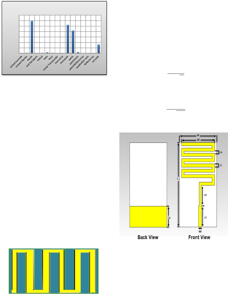
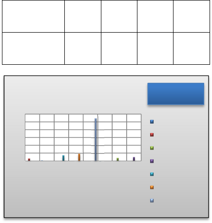
Figure 2: The most antenna type used for Cubesat.
Based on the collected information and standards
for the CubeSat deployed in orbit during the period
2000 - 2019, the analysis of these data lead to build
the Figs. (1) and (2). These Figures help us to select
the frequency band and the antenna type as follows:
According to Figure 1, most of the Cubesat
antenna operates at the licensed lower UHF
band (420 – 450 MHz).
According to Figure 2, most of the Cubesat
antenna uses dipole or monopole type.
4 MEANDER LINE ANTENNA
The meander line antenna can be designed by a set
of horizontal and vertical lines and the combination
of these lines will form the turns of meander line
antenna as shown in Fig.3. The meander line
antenna is a transformation of monopole and dipole
antenna and was proposed to reduce antenna size by
bending the monopole into right angle pends and
these pends will form the antenna. The idea of a
meander line antenna is to fold the conductor back
and forth to make the antenna size smaller
(Ogherohwo, 2015 and M. J. Ma, 2010).
Figure 3: Meander Line Structure.
5 PRIMARY DESIGN OF THE
PROPOSED MEANDER LINE
ANTENNA
The primary design of printed meander line antenna
was designed using CST microwave studio. The
antenna was designed depending on the equations
(1), (2), (3) and the parametric study on the antenna.
The height of the substrate was found by:
ℎ
0.3𝑐
2𝜋𝑓
√
ɛ
(1)
The length of the patch was calculated for the
equation:
𝐿
=
𝑐
2
𝑓
ɛ
(2)
Where ɛ
the effective dielectric constant.
Figure 4: The primary design of meander line monopole
antenna.
The antenna printed on FR-4 substrate (ɛ
=4.3) of
a thickness h=1.6 mm and area of W×L. The feed
line was chosen to have a length of Lf and width of
Wf to provide the 50Ω impedance matching as
shown in Fig.4.
0
20
40
60
80
100
120
140
No. Of Antennas
Types of antennas
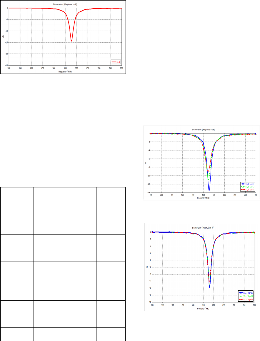
Figure 5: The return loss of the primary designed antenna.
The antenna size was appropriate for the CubeSat
size as it has dimensions of 80×45 mm which is
suitable and covering less than a half of the CubeSat
face. The antenna operates at 578 MHz with return
loss of -14.4 dB as shown in Fig. 5. The operating
frequency was inappropriate for the TTC application
of CubeSat which required being in the range of the
licensed band (420-450) MHz. The radiation
efficiency was about 87% which is suitable value for
the antenna. The values of the antenna dimensions
are chosen using the above equations and are shown
in Table 2.
Table 2: The dimensions of the primary designed antenna.
Dimension
Description
Value(mm)
L
Total antenna length
80
W
Total antenna width
45
Ll
The meandered line width
3
Ls
The spacing between turns
2
Wl
The meandered line length
40
Ll1
The length of the line
between the feed line and
the antenna
22.5
Lf
The feed line length
20
Wf
The feed line width
3.14
Lg
The ground plane length
20
In order to reduce the operating frequency of the
antenna to be appropriate for TTC application of
CubeSat the antenna required to be modified.
6 MODIFIED MEANDER LINE
ANTENNA AND THE
PARAMETRIC STUDY
Some modifications were applied on the primary
design in order to reduce the operating frequency to
be suitable for the CubeSat application. These
modifications are discussed in the below subsections:
6.1 Ground Plane Modification
In order improve the antenna radiation, radiation
efficiency and to reduce the coupling between the
antenna and the CubeSat structure, some
modifications were applied on the ground plane. The
effect of changing the ground plane dimensions are
shown in Fig. 6 and 7.
Figure 6: The effect of the ground plane length on the
return loss.
Figure 7: The effect of the ground plane width on the
return loss.
6.2 Meander Lines and Feed Line
Modifications
The modifications on the number of turns, the
spacing between turns, the line width and the feed
line were applied in order to reduce the operating
frequency. Also, a thin conducting pin was added
between the lined to reduce the path of the surface
current and this will leads to reduce the operating
frequency. The parametric study on all of these
modifications was done as shown in Fig. 8, 9 and 10.
Figure 8: The effect of increasing the number of lines on
the return loss.
Figure 9: The effect of changing the line width on the
return loss.
Figure 10: The effect of changing the thin pins width on
the return loss.
7 PROPOSED PRINTED
MEANDER LINE MONOPOLE
ANTENNA WITH MODIFIED
FEEDING SYSTEM
The final design for the modified printed meander
line monopole antenna which composed of
symmetrical meandered lines and thin conducting
pins between these lines is shown in Fig. 11.
Figure 11: Proposed meander line monopole antenna.
The values of the final dimensions for the proposed
antenna are shown in Table 3. From the table it can
be seen that the antenna dimensions are suitable for
the CubeSat size which are 80×45 mm. This size
will leave additional space for the solar cells and
cover less than a half of the CubeSat face.
Table 3: The final dimensions of the proposed antenna.
Dimension Description Value(mm)
L Total antenna length 80
W Total antenna width 45
Ll The meandered line width 2
Ls The spacing between turns 2
Ws 1 The spacing between the pins
and the meandered lines
3
Wl The meandered line length 40
Ll 1 The length of the line
between the feed line and the
antenna
8
Lf The feed line length 12
Wf The feed line width 3.14
Lg The ground plane length 8
Wg The ground plane width 25
Wp The thin pins width 0.5
h The substrate height 1.6
7.1 Simulation Results
All the simulation results of the proposed antenna
were in the regulated and accepted ranges for the
CubeSat application. The operating frequency and
the return loss for the proposed antenna are shown in
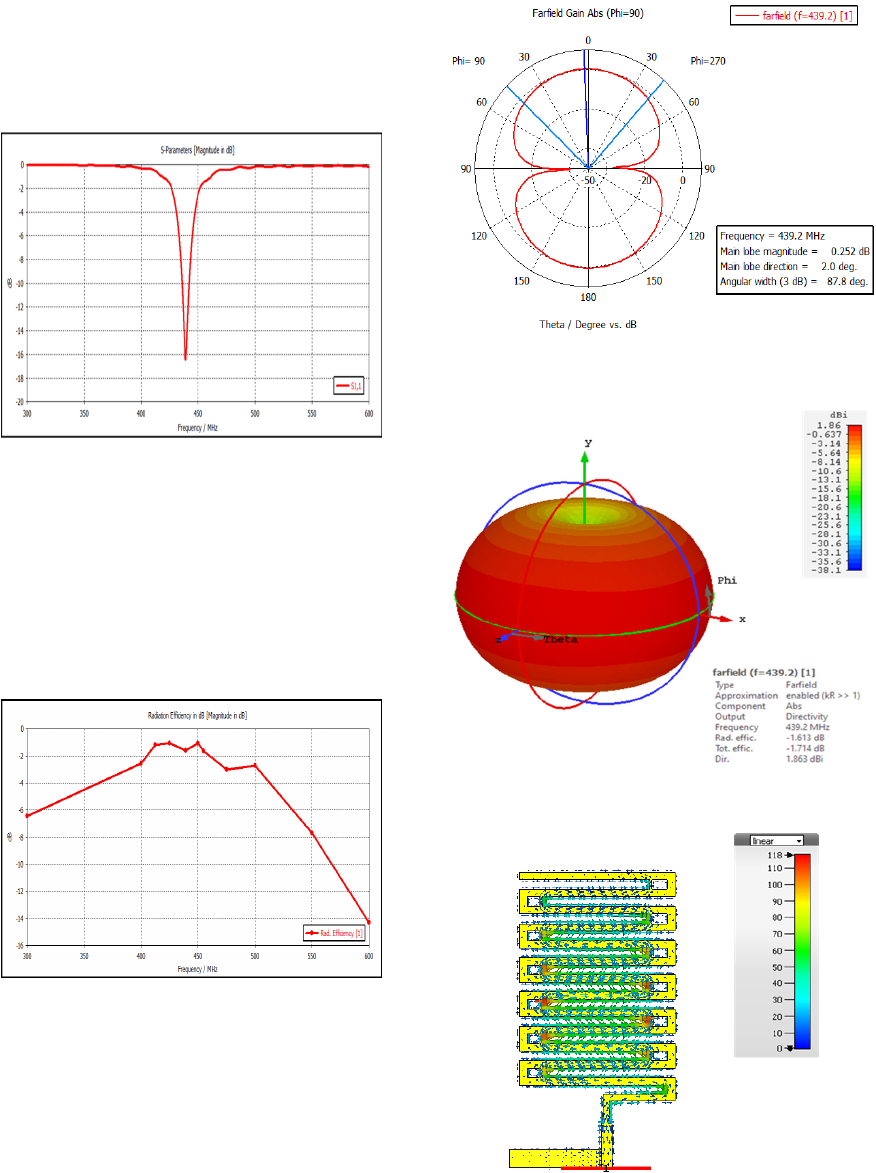
Fig.12. The proposed antenna operates at 439 MHz
with a return loss of – 16.5 dB.
Figure 12: The return loss and operating frequency of the
proposed antenna.
The proposed antenna has a good radiation
efficiency of 80% at 439 MHz as shown in Fig.13.
The gain of the proposed antenna was recorded as a
positive value of 0.3 dB at 439 MHz for the
proposed antenna. This value of gain is acceptable
value as the TTC application does not required an
antenna with high gain.
Figure 13: The radiation efficiency of the proposed
antenna.
Fig. 14 shows the 2-D pattern of the far field
directivity for the proposed meander line monopole
antenna and Fig. 15 shows the 3-D pattern of the far
field directivity for the proposed antenna. The
proposed antenna has achieved wide coverage or
near Omni-directional radiation pattern at the
required frequency. The surface current of the
proposed meander line antenna is shown in Fig. 16.
Figure 14: 2-D pattern of the far field directivity of the
proposed antenna.
Figure 15: The 3-D pattern of the far field directivity for
the proposed antenna.
Figure 16: The surface current of the proposed antenna.
7.2 Fabrication Results
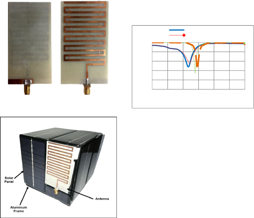
The proposed printed meander line monopole
antenna with modified feeding system was
fabricated on FR-4 substrate of dielectric constant
ɛ
=4.3 of a thickness 1.6 mm as shown in Fig.17.
The return loss of the fabricated antenna was
measured using Vector Network Analyzer (VNA).
The antenna was firstly tested without the CubeSat
and then tested when located on the fabricated
structure of CubeSat. Fig.18 shows the fabricated
antenna when located on 1U CubeSat structure.
Figure 17: The fabricated antenna (Front view and Back
view).
Figure 18: The fabricated antenna with 1U CubeSat.
The return loss and the operating frequency of
the fabricated and simulated design of the proposed
antenna when tested with and without the CubeSat
structure are shown in Fig. 19. It can be seen from
the figure that the fabricated antenna resonates at
lower frequency than the simulated design. The
fabricated antenna radiates at 423 MHz when tested
without the CubeSat which is in the range of the
licensed band (420-450 MHZ). The value of S11 in
VNA was -11.5 dB at 423 MHz. The measured band
width is 11 MHz at -10 dB which is suitable for the
application of TTC of CubeSat.
The return loss of the antenna was -12.8 dB at
419 MHz when the antenna located on the CubeSat,
That’s mean the antenna resonate at lower frequency
when located on the CubeSat as shown in Fig. 19.
The band width was increased to 15 MHz compared
to the bandwidth of the antenna without the
CubeSat. From the collected measurements of the
fabricated antenna, the results of the fabricated
antenna are all in the acceptable ranges and suitable
for real-time applications of TTC of CubeSat.
Figure 19: The fabricated and simulated results of the
proposed antenna.
8 COMPARISON WITH OTHER
WORKS
Several types of CubeSat antennas were designed in
the last few years. These designs are different in
dimensions, lower edge frequency, upper edge
frequency and bandwidth. This section presents a
comparison between the designed antenna and
different antennas were designed for the CubeSat
applications in terms of size, operating frequency,
bandwidth, and compatibility of CubeSat. The
comparison also includes the factor Bandwidth to
Dimension Ratio (BDR) in order to provide an
equitable comparison between models in different
bands. The BDR was calculated depending on below
equation (3) and (4). Table 4 presents the
comparison between the designed antenna and other
CubeSat antennas.
-25
-20
-15
-10
-5
0
300 350 400 450 500 550 600
S-Parameters (dB)
Frequency / MHz
Measured with CubeSat
Measured without CubeSat

𝐵𝐷𝑅 =
𝐵𝑊%
𝜆𝑙𝑒𝑛𝑔𝑡ℎ × 𝜆𝑤𝑖𝑑𝑡ℎ
(3)
𝐵𝑊% =
2(
𝑓
ℎ−
𝑓
𝑙)
(
𝑓
ℎ+
𝑓
𝑙)
× 100%
(4)
Where λ is the wavelength of the lower end
resonance frequency, BW% is the percentage
bandwidth, 𝑓ℎ is the higher end resonance
frequency and 𝑓𝑙 is the lower end resonance
frequency.
Table 4: Comparison with other works.
Antenna Dimensions Bandwidth BDR
Compatibility
of CubeSat
Inverted F
Antenna
(T. Alam,
2018)
100 × 100
mm
0.149λ ×
0.149λ
447.5 –
453.5
MHz
1.33%
59.9
Compatible
with CubeSat
But cover all
the CubeSat
face and have
design
complexity
Patch
Antenna
(Y. Yao,
2016)
110 × 110
mm
0.57λ ×
0.57λ
1575 -
1721 MHz
8.85%
27.2
Not compact
enough. Does
not cover the
licensed
lower UHF
band (420-
460 MHZ)
Dipole
Antenna
(Mehul K. S,
2016)
200 mm
0.14λ
220 - 267
MHz
19.3%
137.8
Compatible
with CubeSat
but need
complex
deployment
mechanism
Monopole
Antenna
(E. Pittella,
2013)
175 mm
0.25λ
435-438
MHz
0.68%
2.7
Compatible
with CubeSat
but have
Deployable
complexity
Microstrip
Patch
(G.
Kakoyiannis,
2008)
120 × 170
mm
0.17λ ×
0.25λ
435 - 437
MHz
0.45%
10.5
large and not
compatible
with 1U
CubeSat
Meander line
monopole
(J. Fan, Z.
Lei, 2014)
155 × 52
mm
0.22λ ×
0.074λ
426-436
MHz
2.3%
143.74
Too large and
not
compatible
with 1U
CubeSat
Proposed
Design
80 × 45
mm
0.11λ ×
0.06λ
434 - 444
MHz
2.2%
333.3
Compatible
with 1U and
2U CubeSat
and free from
deployment
complexity
9 CONCLUSION
The small size of CubeSat and the low operating
frequency represent the major challenge to design a
miniaturized antenna with acceptable performances.
This paper presents antenna design geometry for
CubeSats. The proposed antenna topology is based
on the meander line type. The antenna was
simulated, implemented and tested successfully. The
size of the designed antenna (80mm×45mm) was
suitable for the CubeSat size and cover less than a
half of the CubeSat face which gives additional
space for the solar panels and other components.
Finally, the antenna have been designed on FR-4
substrate using CST software, also it has been
implemented, and the measurements of the
implemented antenna match the results of the design
with insignificant errors due to the limited ability of
the fabrication machine and other limitations.The
work in this thesis can be extended in the future by
using high dielectric constant substrate can be used
to increase the miniaturization level. More than one
miniaturization techniques can be used to increase
the miniaturization level. Gain and bandwidth
enhancement of a miniaturized meander line so that
the antenna can be used for both TTC application
and payload data communication. Lowering the
effect of the CubeSat structure on the antenna.
ACKNOWLEDGMENT
The authors would like to acknowledge Dr. Ghassan
N. Jawad from the University of Baghdad for
providing the measurement results.
REFERENCES
S. Gao, K. Clar, M. Unwin, J. Zackrisson, W. A. Shiroma,
J. M. Akagf, K. Maynard, 2009. “Antennas for
Modern Small Satellites,” IEEE Antennas and
Propagation MagaZine, Vol. 51, No.4.
F. EM Tubbal, R. Raad, K. WU Chin, 2015. “A Survey
and Study of Planar Antennas for Pico-Satellites,”
IEEE, vol. 3.
Y. Yao, S. Liao, J. Wang, K. Xue, E. A. Balfour, Y. Luo,
2016. “A New Patch Antenna Designed for CubeSat,”
IEEE Antennas & Propagation Magazine, vol. 16.
T. Alam, M. T. Islam, Md. A. Ullah, M. Cho., 2018.” A
Solar Panel-Integrated Modified Planner Inverted F
Antenna for Low Earth Orbit Remote Sensing
Nanosatellite Communication System,” Sensors
journal. Vol. 2480.
Mehul K. S, Karthikeya G. S, T. Tanjavur, A. Prasanna,
K. Veeramalai, 2016. “VHF Right Angled Planar
Dipole Antenna Array for Microsat Application,”
IEEE. Vol.
Ogherohwo, E. P, Mado, S.D,and Eggah, M.Y, 2015.
"Design and Analysis of Meander Microstrip Antenna
at Wireless Band,” International Journal of Computer
Applications, Volume 111 – No 6.
The CubeSat Program, 2009. “Cubesat Design
Specification”, California Polytechnic State
University, Regulations and Standards.
N. Mohi, J. S. Aziz, L. A. Salman, 2015. CubeSat
Communication System, a New Design Approach,
IJCSET(www.ijcset.net), Vol 5, Issue 12, 417-422.
NASA Group, 2014. “NASA Procedural Requirements for
Limiting Orbital Debris”, Responsible Office : Office
of Safety and Mission Assurance.
M. J. Ma, K. Deng, 2010. “The study and implementation
of meander-line antenna for an integrated transceiver
design”, M.Sc. thesis in electronics and
telecommunications, University of GAVLE,
ITB/Electronics.
J. Wiley, Sons, 2006. “Antenna theory analysis and
design, 3rd ed”, Published by John Wiley & Sons, Inc.,
Hoboken, New Jersey,
E. Pittella, S. Pisa, and A. Nascetti, 2013. "Design of an
Antenna System for CubeSat Satellites," in Proc. 2nd
Int. Academy Astronautics Conf. University Satellites
Missions and CubeSat Winter Workshop.
G. Kakoyiannis and P. Constantinou, 2008. "A compact
microstrip antenna with tapered peripheral slits for
CubeSat RF Payloads at 436MHz: Miniaturization
techniques, design & numerical results," in Satellite
and Space Communications, IWSSC. IEEE
International Workshop.
J. Fan, Z. Lei, Y. Xie and M. Man, 2014. “Bandwidth
Enhancement for Low Frequency Meander Line
Antenna”, Progress In Electromagnetics Research,
Vol. 51.
