
Effect of Stainless Steel Weld Overlay Deposit on the Hardness of API
5L Pipes
Adhe Aryswan
*
, Nurul Laili Arifin, Hanifah Widiastuti and Dois Ditya Wahyu Kirana
Mechanical Engineering, Politeknik Negeri Batam, Batam, Indonesia
Keywords: Weld Overlay, Vickers Hardness, Corrosion Resistant Alloys.
Abstract: To improve the corrosion resistance of API 5 L pipe, we applied a weld overlay of UNS S31603 stainless steel
as filler metal. To confirm the modified material’s quality, we determine the hardness of the material to be
compared to API 5LD specification. We performed Vickers hardness tests at the corrosion-resistant alloy
(CRA) area and the base metal and heat-affected zone. The tests show that the deposition improves the material
hardness by 7.32%. The average Vickers hardness number at the CRA area was 212.32 HV, with 230 HV.
Referring to API 5LD qualification, the maximum hardness allowed at the CRA area is 300 HV. Thus, the
material processed by weld overlay has an acceptable quality.
1 INTRODUCTION
One of the most advantageous ways to transport oil
and natural gas to date is by pipeline due to its low
cost and large capacity (Zhou et al., 2016). Line pipes
are predominantly controlled by API 5L, which is
now also an ISO specification (ISO 3183), regulating
their manufacturing, testing, and classification
(Singh, 2017). However, the corrosive impurities like
water, hydrogen sulfide, and carbon dioxide during
extraction cannot be completely removed during
processing and transportation (Li et al., 2017). These
impurities could potentially cause material
deterioration due to serious corrosion damages
(Obanijesu, 2009). Switching the materials to the one
with higher resistance to corrosion is not considered
a possible solution since they generally possess lower
strength.
A possible solution to provide a material that
possesses high strength and corrosion resistance is to
perform the weld overlay with metallurgically
compatible corrosion resistant alloy to clad the steel
(Kannan and Murugan, 2006). The term weld
overlay, also known as weld cladding, is a method to
improve properties of a base metal by applying a
relatively thick layer of dissimilar weld metal (Rao,
Reddy, and Nagarjuna, 2011). Austenitic stainless
steels (ASS) are well known for their great corrosion
resistance (Gupta and Birbilis, 2015; Lapechenkov et
al., 2020) and are proven to be successfully added to
high strength low alloy steel (Rao, Reddy, and
Nagarjuna, 2011). Hence, they are good candidates to
be applied by weld overlay in this study. Lima et al.,
2020 reported that samples cladded by GTAW-
hotwire show an impressive corrosion resistance.
Nevertheless, after the steel is cladded, its
physical properties also change. Therefore, it is
required to investigate whether the fabricated
material still meets the standard's qualifications. One
significant property of materials directly related to its
lifetime is hardness (Lewis et al., 2019). Hardness
measurement is a mandatory step in manufacturing
many products, and one of the standard hardness tests
is Vickers (Daemi, Tomkowski, and Archenti, 2020).
This study reported a weld overlay by depositing
austenitic stainless steel on API 5L pipe by the
GTAW process. The fabricated material was then
examined by the Vickers hardness tests to ensure that
the resulting material has still complied with API
5LD specification, a standard for seamless and
welded clad steel pipe with enhanced corrosion-
resistant properties (American Petroleum Institute,
2015). It is shown that the resulting material could
meet the related standard. Hence, the weld overlay
proposed in this study could be performed on
pipelines to improve their resistance against
corrosion.
Aryswan, A., Arifin, N., Widiastuti, H. and Kirana, D.
Effect of Stainless Steel Weld Overlay Deposit on the Hardness of API 5L Pipes.
DOI: 10.5220/0010352801190123
In Proceedings of the 3rd International Conference on Applied Engineering (ICAE 2020), pages 119-123
ISBN: 978-989-758-520-3
Copyright
c
2021 by SCITEPRESS – Science and Technology Publications, Lda. All rights reserved
119

2 MATERIALS AND METHODS
2.1 Base Metal
Specimens was prepared in accordance with API 5L
specification. Seamless pipes was used as base metal,
with specification API 5L Gr.L450Q PSL 2, P-No 1
Gr. No 2, thickness 8.18 mm, outside diameter 219.1
mm (8” NPS), heat number J7K5650, length 1000
mm, heat treatment condition: quenched and
tempered, chemical composition (%): C = 0.06; CE
(PCM) = 0.14; CE (IIW) = 0.31. Weld overlay length
= 1000 mm.
2.2 Filler Metal
Filler metal applied in this study was austenitic
stainless steel (ASS) UNS S31603. The welding
process used two variant of filler metal, namely:
Daiko ER309LMo size 1.2 mm with
specifications EN ISO 14343-A: G 23 12 2 L
AWS A5.9 (ER309LMo) modified, heat
number: 547158, SFA-5.9, F-No.6, A-No.8.
Novametal ER316L size 1.2 mm with
specifications ASME II PART C: SFA-5.9
AWS A5.9/A5.9: ER316L EN ISO 14343-A:
19 12 3 L, heat number: 59583, SFA-5.9, F-
No.6, A- No.8.
The elemental contents of base metal and filler
metals can be seen in the following Table 1, while the
mechanical properties in Table 2.
The weld overlay application was illustrated in the
following Figure 1, with filler metal Daiko 309LMo
as the inner first layer and Novametal 316L as the
outer one.
Table 1: Elemental contents of materials.
Elemental
Contents
(%)
Material
Base
Metal
Daiko
309LMo
Novametal
316L
C 0.06 0.0009 0.010
Si 0.21 0.300 0.310
Mn 1.24 1.430 1.940
P 0.007 0.018 0.019
S 0.001 0.004 0.009
Cu 0.01 0.087 0.140
Cr 0.17 21.240 18.540
Ni 0.02 14.740 11.800
Mo 0.01 2.570 2.580
Table 2: Mechanical properties of materials.
Mechanical
Properties
Base
Metal
Daiko
309LMo
Novametal
316L
Tensile Strength
(MPa)
581 600 510
Yield Strength (MPa) 506 430 320
Elongation (%) 34 35 25
Impact Energy (J) N/A 100 80
2.3 Welding Process
Welding process was conducted by DCEN pulsed gas
tungsten arc welding (GTAW) without hot wire. The
welding position was 1G, with the pipe placed
horizontally and rotated counterclockwise. Welding
travel was performed step-back and moved around
2.8 – 3.6 mm. The tungsten was 3.2 mm EWLa-2type,
and the welding machine was Fronius 4500A. The
welding parameters were carried out according to
PQR shown in Table 3.
The weld overlay application was illustrated in the
following Figure 1, with filler metal Daiko 309LMo
as the inner first layer and Novametal 316L as the
outer one.
2.4 Vickers Hardness Tests
The examination performed by Vickers hardness
tester Mitutoyo model HV-113 S/N 500041203, with
diamond indenter (face angle 136
°
), and load 10 kgf.
The method used in this study complies with ASTM
E92 (ASTM International, 2017), that is a standard
method for testing Vickers's hardness of a metallic
material. This study conducted a Vickers hardness
test on two specimens, following the code that refers
to ASME Section IX Qualification (American
Society of Mechanical Engineers, 2010). Each of
them tested at specific test location points based on
API 5LD specification for CRA Clad or Lined Steel
Pipe (American Petroleum Institute, 2015), and
Aramco Drawing AB-036386, respectively. Those
points are illustrated in the following Figure 2 and
Figure 3.
Figure 1: Weld overlay layout.
ICAE 2020 - The International Conference on Applied Engineering
120
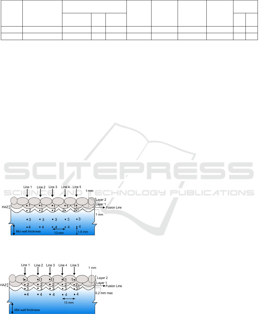
Table 3: Welding parameters.
Weld
Pass/
Layer
Process, Current
Type, Polarity
Filler Metal
Amps
Range (A)
Volts Range
(V)
Travel Speed
(mm/min)
Preheat and
Interpass
(°C)
Heat Input
(kJ/mm)
Classification
Size
(mm)
Speed
Range
Min Max
Layer 1 GTAW/DCEN ER309LMo 1.2 2 × 1000 190 – 230 13.1 – 14.5 400 32 – 160 0.37 0.50
Layer 2 GTAW/DCEN ER316L 1.2 2 × 1300 200 – 240 12.5 – 13.5 400 40 – 178 0.38 0.49
As shown in the previous Figure 2, the test
consists of 5 lines and each line was composed of 4
points, specifically: No. 1 at layer 1, No. 2 at HAZ,
No. 3, and No. 4 at base metal. Figure 2 also shows
the distances among lines. Those points out where the
exact positions are. However, each line is 13 mm
apart. Layer 1 and fusion line are 1 mm apart, the
same as fusion line and HAZ.
Specimen 2 was tested by 5 lines with 4 points
each, as shown in Figure 3. The points No. 1 located
at layer 2, No. 2 at layer 1, No. 3 at HAZ, and No. 4 at
base metal. The distances of lines and points, as
shown in Figure 3, are similar to Figure 2, except the
distance between fusion line and HAZ is a maximum
0.2 mm apart. Acceptance criteria of the examination
were obtained from API 5LD specification
(American Petroleum Institute, 2015) that covers the
cladded API 5L pipe qualifications. The hardness test
requirements are shown in Table 4.
Figure 2: Specific test location points of specimen 1 based
on API 5LD specification for CRA Clad or Lined Steel
Pipe.
Figure 3: Specific test location points of specimen 2 based
on Aramco Drawing AB-036386.
Since austenitic stainless steel was used as filler
metals in this study, the maximum HV allowed at the
CRA area is 300 HV10, while the hardness measured
at base metal and HAZ area should be less than 248
HV10. The number 10 following HV scale represents
the applied test force of 10 kgf (ASTM International,
2017).
3 RESULTS AND DISCUSSION
Data collected from the Vickers hardness test of both
specimens are shown in Table 5 and Table 6. As
demonstrated by Table 5, the average hardness of
specimen 1 in the CRA area, HAZ, and base metal
were 208 HV; 196.8 HV; and 195 HV, respectively.
Table 6 shows that specimen 2 had average hardness
in the outer layer 2, inner layer 1, HAZ and base metal
sequentially were 213.8 HV; 219.6 HV; and 203.4
HV for the latter two. It can be calculated that the
average hardness in the CRA area if both specimens
are added is 212.35 HV. Referring to Table 4, the
Vickers hardness number of CRA area in both
specimens followed the acceptance criteria since the
HV obtained was lower than 300 HV. On the other
hand, HAZ and the base metal area was qualified with
hardness numbers not exceeding 248 HV.
According to the measured data, it was recognized
that the material hardness was increased due to the
weld overlay. Comparing the HV at CRA and base
metal, it is known that the hardness of specimen 1 was
improved by 6.67%, while specimen 2 had
increments of 5.11 % at layer 2 and 7.96% at layer 1.
Hence, weld overlay increases the material’s hardness
around 7.32%. This observation might be due to the
carbon diffusion hardens the weld metal through solid
solution strengthening (Akhatova et al., 2020). The
fact that layer 1 was having the highest HV is
expected due to being sandwiched between the base
metal and layer 2, so the area contains more diffusion
then more defects. However, it is required for further
study to confirm the chemical composition in each
layer.
Effect of Stainless Steel Weld Overlay Deposit on the Hardness of API 5L Pipes
121
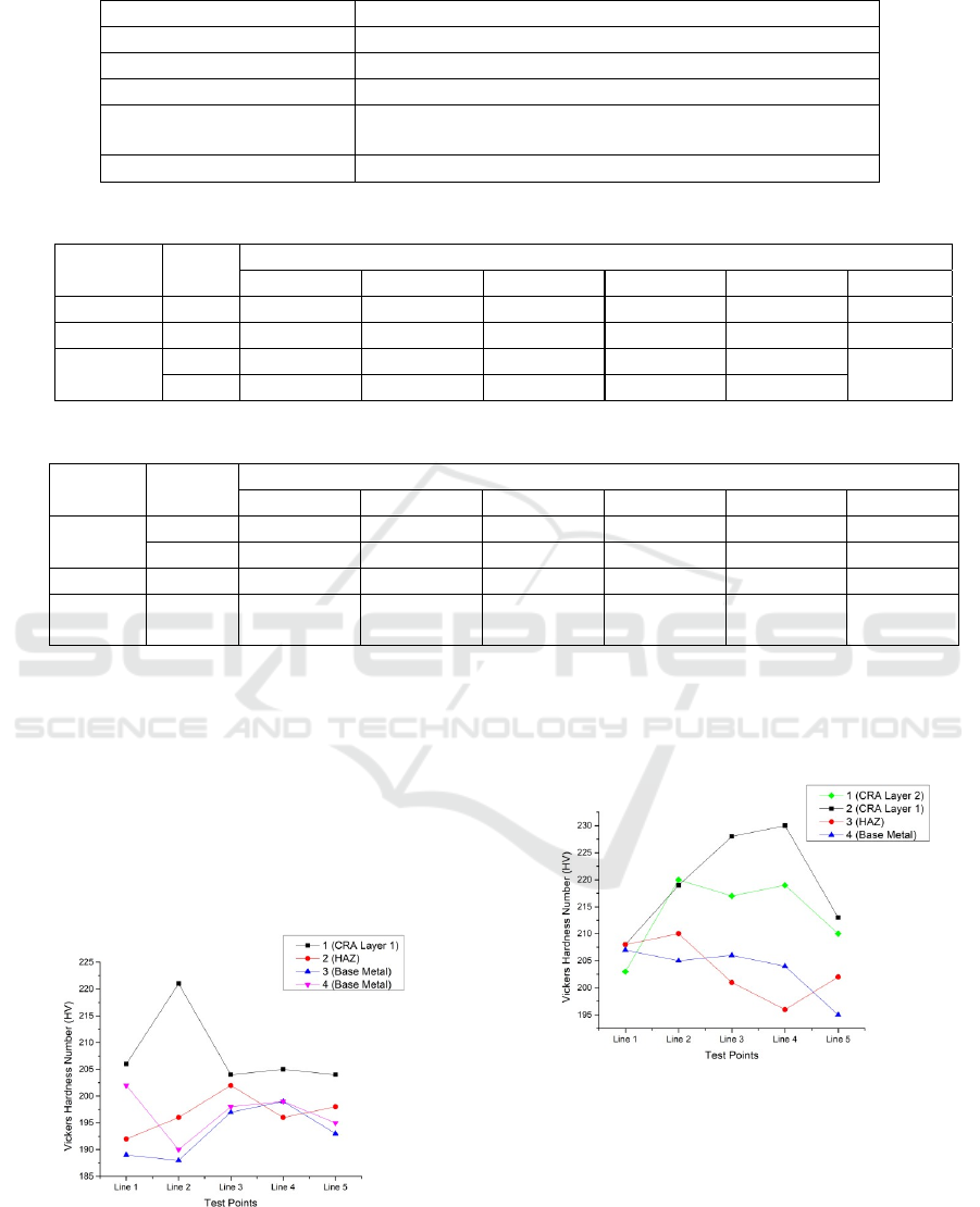
Table 4: Acceptance criteria for Vickers hardness test (American Petroleum Institute, 2015).
Material Maximum HV allowed
Ferritic steel base metal 248 HV10 at all locations unless otherwise agreed
Austenitic stainless steels 300 HV10 in all locations
22% Duplex stainless steels 300 HV10 in the parent material and 334 HV10 in the weld and HAZ
25% Duplex stainless super
duplex steels
300 HV10 in the parent material and 378 HV10 in the weld and HAZ
Nickel base alloys 345 HV10 in all locations
Table 5: Measured hardness of specimen 1.
Test
Location
No
Vickers Hardness Number (HV)
Line 1 Line 2 Line 3 Line 4 Line 5 Average
CRA 1 206 221 204 205 204 208
HAZ 2 192 196 202 196 198 196.8
Base
Metal
3 189 188 197 199 193
195
4 202 190 198 199 195
Table 6: Measured hardness of specimen 2.
Test
Location
No
Vickers Hardness Number (HV)
Line 1 Line 2 Line 3 Line 4 Line 5 Average
CRA
1 203 220 217 219 210 213.8
2 208 219 228 230 213 219.6
HAZ 3 208 210 201 196 202 203.4
Base
Metal
4 207 205 206 204 195 203.4
As seen in Table 6, the hardness of layer 2
relatively lower than layer 1. Apart from the intrinsic
mechanical properties of Novametal 316L that have
the most insufficient tensile strength among materials
used, we expect its position relative to fusion line lead
to carbon diffusion in that area was lower than the
layer 1. Consequently, the outer layer of the clad had
lower hardness than the inner one. The following
Figure 4 and Figure 5 represent the measured HV
numbers of specimen 1 and 2.
Figure 4: Graphical representation of specimen 1 measured
Vickers hardness number (HV).
Those graphs show that the layer 1 consistently
being the hardest part of material. However, it is yet
unclear why the hardness of HAZ and base metal
being alternately fluctuate.
Figure 5: Graphical representation of specimen 2 measured
Vickers hardness number (HV).
4 CONCLUSIONS
In this study, seamless pipes were cladded with two
different filler metals to increase CRA’s corrosion
resistance. The hardness values on the CRA are
higher than those for the untreated metal.
ICAE 2020 - The International Conference on Applied Engineering
122

Nevertheless, the fabricated material could meet the
acceptance criteria in API 5LD standard. However,
further study is required to confirm whether the
stainless steel overlay could improve the material’s
corrosion resistance properties.
ACKNOWLEDGEMENTS
The authors thank PT. Cladtek Bi-Metal
Manufacturing Batam and PT. Hi-Test Laboratory of
Mechanical Testing Batam for their technical
supports.
REFERENCES
Akhatova, A. et al., 2020. Microstructural and mechanical
investigation of the near fusion boundary region in
thermally aged 18MND5/alloy 52 narrow-gap
dissimilar metal weld. Materials Science and
Engineering. Elsevier B.V., 788(May), p. 139592. doi:
10.1016/j.msea.2020.139592.
American Petroleum Institute, 2015. CRA Clad or Lined
Steel Pipe. In API Specification 5LD.
American Society of Mechanical Engineers, 2010. Welding
and brazing qualifications, ASME Boiler and Pressure
Vessel Code Section IX: Welding and Brazing
Qualifications. New York: American Society of
Mechanical Engineers. doi: 10.1115/1.859872.ch25.
ASTM International, 2017. E92 Standard Test Methods for
Vickers Hardness and Knoop Hardness of Metallic
Materials, ASTM Book of Standards. West
Conshohocken. doi: 10.1520/E0092-16.Copyright.
Daemi, B., Tomkowski, R., Archenti, A., 2020. High
precision 3D evaluation method for Vickers hardness
measurement. CIRP Annals. Elsevier Ltd, 69(1), pp.
433– 436. doi: 10.1016/j.cirp.2020.03.022.
Gupta, R. K., Birbilis, N., 2015. The influence of
nanocrystalline structure and processing route on
corrosion of stainless steel: A review. Corrosion
Science. Elsevier Ltd, 92, pp. 1–15. doi:
10.1016/j.corsci.2014.11.041.
Kannan, T., Murugan, N., 2006. Effect of flux cored arc
welding process parameters on duplex stainless steel
clad quality. Journal of Materials Processing
Technology, 176(1–3), pp. 230–239. doi:
10.1016/j.jmatprotec.2006.03.157.
Lapechenkov, A. et al., 2020. Comparative analysis of the
corrosion resistance of UNS S31200 duplex stainless
steel and its analogue. Materials Today: Proceedings.
Elsevier Ltd., (xxxx), pp. 10–13. doi:
10.1016/j.matpr.2019.12.174.
Lewis, R. et al., 2019. Investigation of the influence of rail
hardness on the wear of rail and wheel materials under
dry conditions (ICRI wear mapping project). Wear.
Elsevier B.V., 430–431(January), pp. 383–392. doi:
10.1016/j.wear.2019.05.030.
Li, K. K. et al., 2017. Corrosion Behavior of X70 Pipeline
Steel and Corrosion Rate Prediction Under the
Combination of Corrosive Medium and Applied
Pressure. In Proceedings of the ASME 2017 Pressure
Vessels and Piping Conference. Waikoloa, Hawaii,
USA, pp. 1–6. doi: https://doi.org/10.1115/PVP2017-
65651.
Lima, C. R. C. et al., 2020. Wear and corrosion
performance of Stellite 6® coatings applied by HVOF
spraying and GTAW hotwire cladding. Journal of
Materials Processing Technology. Elsevier,
284(April), p. 116734. doi:
10.1016/j.jmatprotec.2020.116734.
Obanijesu, E. O., 2009. Modeling the H
2
S contribution to
internal corrosion rate of natural gas pipeline. Energy
Sources, Part A: Recovery, Utilization and
Environmental Effects, 31(4), pp. 348–363.
doi: 10.1080/15567030701528408.
Rao, N. V., Reddy, G. M., Nagarjuna, S., 2011. Weld
overlay cladding of high strength low alloy steel with
austenitic stainless steel - Structure and properties.
Materials and Design. Elsevier Ltd, 32(4), pp.
2496–2506. doi: 10.1016/j.matdes.2010.10.026.
Singh, R., 2017. Line Pipes. In Pipeline Integrity
Handbook, pp. 191–198. doi: 10.1016/b978-0-12-
813045- 2.00013-2.
Zhou, Q. et al., 2016. Estimation of corrosion failure
likelihood of oil and gas pipeline based on fuzzy logic
approach. Engineering Failure Analysis. Elsevier Inc.,
70, pp. 48–55. doi: 10.1016/j.engfailanal.2016.07.014.
Effect of Stainless Steel Weld Overlay Deposit on the Hardness of API 5L Pipes
123
