
Application on Survey Implementation of Dredging and Structure for
Energy Reducing Spillway Building at Ladongi Dam
Meivy Carolina Pandey
1
, Muhammad Zainuddin Lubis
1
, Agung Permana
2
, Sidik Dwi Pamungkas
3
and Muhammad Adam
4
1
Geomatics Engineering, Politeknik Negeri Batam, Batam, Indonesia
2
Pejabat Pembuat Komitmen, Ladongi Dam Project, Kolaka Timur, Indonesia
3
Geodetic Engineering, Ladongi Dam Project, Kolaka Timur, Indonesia
4
Civil Engineer, Ladongi Dam Project, Kolaka Timur, Indonesia
sidikdwipamungkas93,adamlawa024}@gmail.com
Keywords: Energy Reduction Building, Role of Survey, Excavation and Structure, Volume.
Abstract: The Energy Reduction Building planned at Ladongi Dam utilized the Type II Olakan Flat Pond Type (USBR
II). Energy absorbers in spillway buildings are very important to reduce the energy of water flow and avoid
damage to rivers. The purpose of this study is to determine the role of the survey in the implementation of
excavation and also the structure buildings in the field and be able to process and present measurement data.
Data field collection consists of 3 working stages: excavation work, working work floor and working wall
structure. The calculation of excavation volume in this final project is carried out by measurement using the
Cross Section and in volume calculation using the Mean Area method. The results from this study are, the
role of the survey in the construction of energy reduction building, the volume of excavation and foundry of
work floors, the dental importance of wall structures, cross-section, 3-dimensional view of excavated land.
LW 33 block dental volume is 138.99 m
3
starting from an elevation of +60.11 to an elevation of +64.50. In
Block LW 33 - LW 35, a landslide occurred in the zone 3 slopes parallel to the structural parapet (El. +64.5 -
El. +67.5) therefore dental filling was carried out, the total required dental volume was 164,954 m
3
. The total
volume of excavation to the work floor elevation is 505,609 m
3
, and the total volume of additional landslide
structures is 893,329 m
3
.
1 INTRODUCTION
Indonesia's rapid population growth makes the role of
water sources significant. The volume of water is
relatively fixed, but the water demand continues to
rise, making humans continue to strive to manage
water sources (Prastumi, 2012). One source of water
that has the potential to be driven to reach the growing
need for water is the river.
Judging from the geographical location and
infrastructure of Southeast Sulawesi Province, East
Kolaka Regency has an equitably large irrigation area
and rivers that have the potential to irrigate
agriculture, natural water sources, etc. One of the
rivers in East Kolaka that can be exploited is the
Ladongi River in Ladongi District. To take advantage
of this potential, the Central Government through
Sulawesi River Region IV Kendari Ministry of
PUPR. Ladongi Dam is planned to have a capacity of
45 million m
3
and is expected to irrigate an area of
3604 ha.
The embankment dam was built by piling up
materials such as a rock, gravel, sand, and soil in a
unique composition with the function of to lift the
water surface in the reservoir (Sosrodarsono, 1977),
Ladongi Dam construction it was engineered to use
the rock fill type dam. Ladongi Dam consists of
several main building constructions, namely main
Dam, spillway, and tunnel, each of which has an
essential and interrelated role. Spillway buildings
have the function to overflow water in dam reservoirs
and to avoid overtopping on dams (Asiyanto, 2011).
The spillway at Ladongi Dam uses Ogee type
overflow type with light level elevation +119.8
meters. Ladongi Dam at spillway area consists of 4
main construction parts, namely flow control,
launchers, energy absorbers, and drainage channels.
40
Pandey, M., Lubis, M., Permana, A., Pamungkas, S. and Adam, M.
Application on Survey Implementation of Dredging and Structure for Energy Reducing Spillway Building at Ladongi Dam.
DOI: 10.5220/0010351400400047
In Proceedings of the 3rd International Conference on Applied Engineering (ICAE 2020), pages 40-47
ISBN: 978-989-758-520-3
Copyright
c
2021 by SCITEPRESS – Science and Technology Publications, Lda. All rights reserved

The energy reducer building planned at Ladongi
Dam uses the Olakan Flat Type II (USBR II) Pool
type. This type is suitable for flow with high
hydrostatic pressure and massive outflow
(Sosrodarsono, 2016). Energy absorbers in spillway
buildings are very important to reduce the energy of
water flow and avoid damage to rivers. Damage that
occurs is usually in the form of scouring on the river
body caused by high energy content and supercritical
flow due to changes in the slope of the dam lighthouse
(Ratnawati, 2009). Therefore, before the flow of
water flowing into the river, it has to slow down and
changed in sub-critical flow conditions, so that no
scouring occurs, which causes degradation on the
riverbed (Prastumi, 2012).
In the implementation of the construction of the
energy reducer structure has some factors that must
be considered, such design structure, plan elevation,
geological structure, and the strength of the slope
structure. During the execution of the Ladongi Dam
spillway, landslides have occurred at the slope
structure in the launch area that caused by geological
conditions in the area. The existence of landslides in
the area resulted in changes in the method in the
excavation process and the energy reducer structures.
The role of surveys is very important in the
implementation of spillway work. In the field
implementation, the survey team is generally tasked
with determining location, controlling the excavation
of structural work, and controlling the work of
structures. The purpose of this study was to determine
the role of the survey in the implementation of
excavation and the structure of the Ladongi Dam
energy reducer building, to know the handling and
role of the survey in the landslide area of the energy
reducer at Ladongi Dam. In this final project data
collection is divided into 3 (three) parts, namely:
excavation work, floor work, and wall structure work.
2 RESEARCH METHODS
2.1 Research Design
The results of the study are focused on providing a
picture of the actual state of the object in the study.
Stages of research to be carried out can be seen in
Figure 1.
Data collection techniques used in this study were
carried out by collecting primary data and secondary
data. Primary data was obtained by collecting the data
field directly through field observations and
measurements. Secondary data in this study were
obtained by the Office of the Ladongi Dam
Supervision Consultant PT Binatama Wirawredha
KSO PT Arga Pasca-Rencana and also by the Office
Contractor PT Hutama Karya Bumi Karsa KSO.
Figure 1: Research flowchart.
2.2 Research Location and Time
This research was conducted at Ladongi Dam
Construction Project in East Kolaka Regency,
Southeast Sulawesi Province, where the geographical
location was on coordinates of 4° 08’ 52” – 4° 08’ 53”
South latitude and 121° 52’ 43” – 121° 53’ 34” East
longitude (Figure 2). In this study the location
observed was an energy-absorbing building in an
overflow building (Spillway). The data retrieval and
processing last for 6 months.
2.3 Tools and Materials
In measurement activities, of course, equipment is
needed to support this research activity in data
retrieval and processing as follows:
Software: Microsot Word 2010, Microsoft
Excel 2010, Autocad Civil 2017, SketchUp
2017, Surfer 9.
Figure 2: Research location.
Application on Survey Implementation of Dredging and Structure for Energy Reducing Spillway Building at Ladongi Dam
41
Hardware: Total Station Topcon ES 101,
Waterpass Topcon AT-G6, Statif, Prisma, Bak
Ukur, Meteran, Drone.
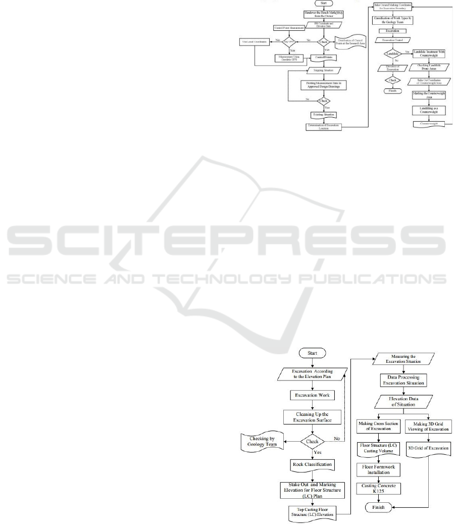
2.4 Dredging Works
Dredging work is the initial stage in carrying out the
work of a building structure, where this excavation
work is carried out to provide land for the building
structure. Stages of dredging works can be seen in
Figure 3.
Before the work is carried out, there are
preparatory stages that need to be considered to
support the implementation of work in the field from
start to finish such as Provision of Data and Working
Drawings, Inspection of Survey Equipment, and
mobilization of Personnel Equipment. In excavation
work, some main things must be considered as
follows:
Point Benchmark (BM), the initial stage in
carrying out survey work in the field surveyors
need to have Benchmark data (BM). BM has a
fixed position value in the form of coordinates
with the appearance of a monument/pale in the
field, which is used as a reference point (Adi &
Aghastya, 2017). BM procurement can be done
by measuring using Geodetic GPS through the
static method or using local coordinates. In this
study, the procurement of BM points was not
carried out because the reference points of BM
were evenly distributed in the research
location.
A Mapping Situation is a mapping activity to
get a detailed description of the work area
project (Susetyo, Tri, & Saputra, 2013). The
measurement for mapping is discovering the
horizontal position and vertical position of each
point in the field (Kustarto, 2012). The
mapping situation in this study concerns for
carried out to find how the topography before
the excavation stage and also use as a factor of
data field checking based on the design
drawings.
Excavation stage, implementation on the field
for excavation work begins with the
determination of the excavation location.
Fixing the area of the excavation is done by
stake out the coordinates and marking the land
boundaries. The coordinate stakeout is to select
the point above the earth's surface using the
coordinates [9], the coordinate stakeout can be
done by using the Total Station. If the
excavation location has been decided,
excavation work can be started. One of the
obstacles that occur during the excavation in
the field is some areas have the potential for
landslides, so during the excavation stage, if a
landslide occurs, it is necessary to handle it by
installing a counterweight.
Figure 3: Dredging work flow chart.
2.5 Work Floor Work
In the implementation of the work floor of a building
structure, the availability of the work floor structure
land must be ensured. Figure 4 is the following stages
in work floor activity.
Measurement of detail points is needed to
describe the situation of the measurement area in
more detail, measurement of detail points can be done
using the tachymetry method. The tachymetry
method is a measuring method of detail points used
in determining the coordinates and height of the detail
points from tie points (Maulidin, 2016). Measuring
height or elevation is the measurement of the height
difference between two points.
Figure 4: Work flow chart of floor.
ICAE 2020 - The International Conference on Applied Engineering
42
Measurement of height difference can be done
with a flat slope measurement tool, measuring the
height difference with a flat slope is the process of
determining elevation or finding a different height
between measured points (Masrul & Anjasmara,
2015). The role of the survey is to ensure that the
excavation area and/or work floor elevation are
following the plan. If the excavation has matched
with the design elevation plan, the geological team
will check to ensure that the excavated land as
compared to the specifications with planning design
by the geological team, height between measured
points (Masrul & Anjasmara, 2015). The role of the
survey is to ensure that the excavation area and/or
work floor elevation are following the plan. If the
excavation has matched with the design elevation
plan, the geological team will check to ensure that the
excavated land as compared to the specifications with
planning design by the geological team.
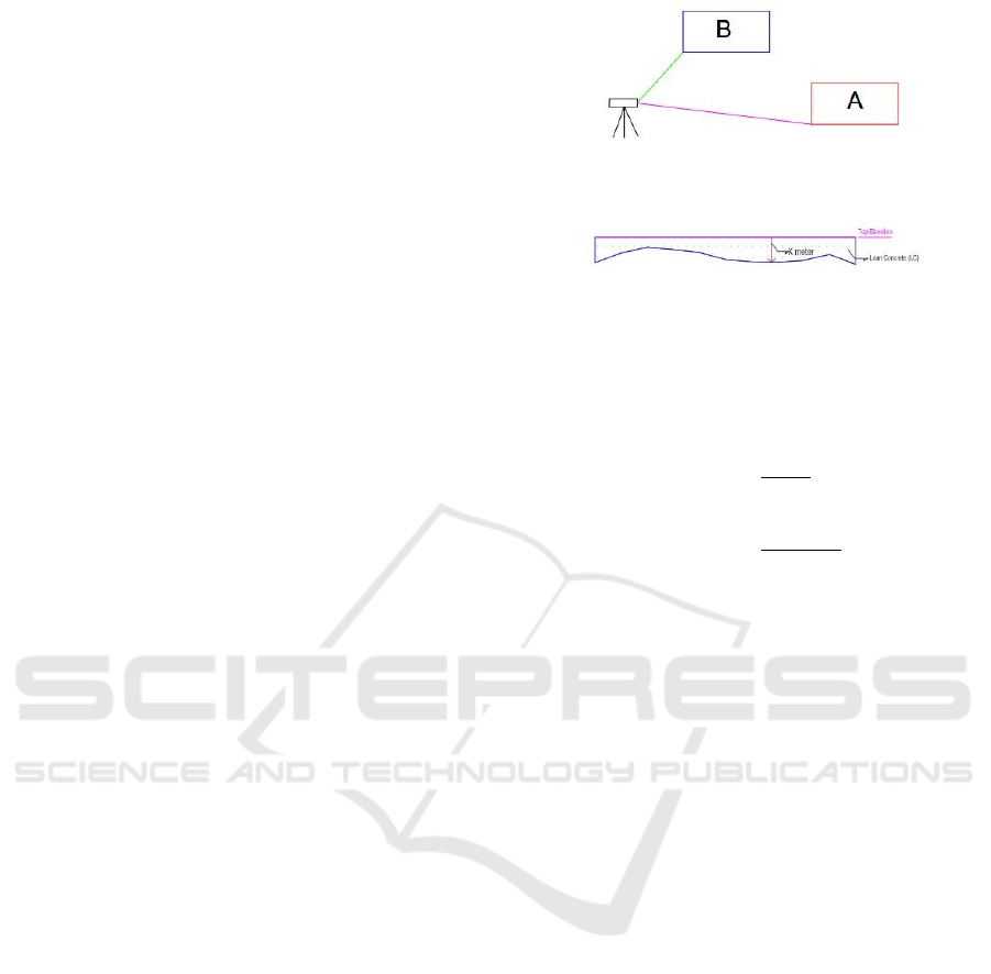
Stake out elevation and work floor marking,
stake out elevation is to determine the point that
will be the elevation limit of the work floor plan
if the excavation of the land has passed the
work floor plan design (Figure 5). In the
implementation of stake out, fixing and
checking reference points is the first step that
must be taken (TS-04, 2011). To fix the work
floor elevation limit, it can be fixed by using
measurement tools, i.e. a water pass, the
accuracy of deter- mining the size depends on
the tools used as well as on the accuracy of
measurement and what can be executed (Frick
& Heinz, 1984). After obtaining the work floor
elevation limit, the work floor boundary
marking is carried out to obtain the work floor
top cast. The implementation of stake out
elevation in the field is carried out using the
formula below, i.e:
Re f Ele(A)WP = Re f Ele(A) + Re f Signs(A) (1)
SignsRead(B) = Re f Ele(A)WP–CastTEle(B) (2)
The excavation situation was measured using
wa- ter pass and meter. Water pass is used to
get full cast from the work floor and work floor
bound- aries (Figure 6). Excavation situation
data is taken by cross technique taken per 1
meter. Through the measurement of the
excavation situation, it can be seen how the
cross-section of excavated land is through the
results of the profile lengthwise and the
transverse profile.
Figure 5: Stake out and work floor elevation marking
techniques.
Figure 6: Data retrieval technique for dredging situation.
The results of this measurement will be processed
to obtain the volume of work floor casting using the
cross-section method with the Mean Area equation
with the following formula (Adi & Aghsatya, 2017):
𝑉
𝐿 (3)
𝑉
𝐿 (4)
Where:
V
n
: nth section average volume (m
3
),
A
1
: Cross-sectional area 1 (m
2
),
A
2
: Cross-sectional area 2 (m
2
),
L : Distance between each section (m).
Figure 7 is the stage of the wall structure work,
which is the final stage in developing the energy
reducing construction. Stakeout and marked elevation
of the nth section from wall design, Stakeout
elevation or vertical stakeout is the measurement of
the main points position and the vertical details of the
building. The first step is, of course, the determination
of the foundation elevation at a predetermined
location through the measurement of horizontal
stakeholder outs. After determining the elevation of
the working wall plan, estimation of the volume of
concrete needed for casting can be estimated. If
landslides occur in the wall structure area, the need
for concrete for casting will increase. The landslide
result, fillings and/or dental casting are carried out to
cover the landslide area so that the initial concrete
requirements according to the plan based on the work
drawings are added to the volume of the landslide.
Calculating volume of the landslide, the survey team
took measurements of the situation of the landslide
area, in this measurement using a meter by calculating
the distance between the structure of the building and
the area affected by the landslide.
Application on Survey Implementation of Dredging and Structure for Energy Reducing Spillway Building at Ladongi Dam
43
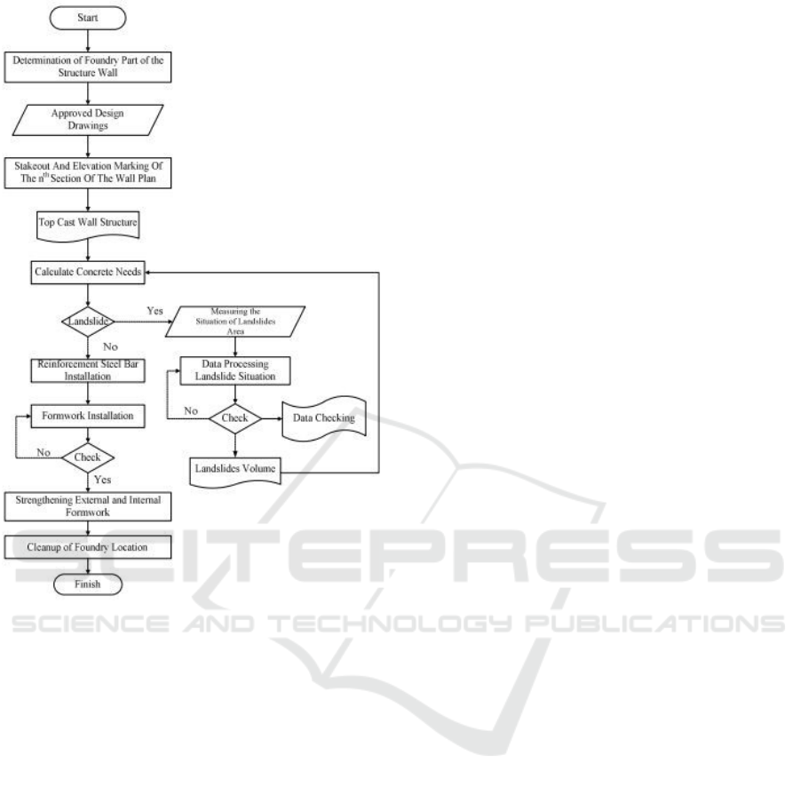
Figure 7: Structure work flow diagram.
3 RESULTS AND DISCUSSION
3.1 Dredging
The excavation process begins with a stakeout and
marking the boundaries of excavated land to be
worked. Excavation work for wall structure work
floors is carried out up to +54.00 m elevation, while
elevations for work floors are required up to +55.00
m elevation.
In the excavation work, the survey team has the
role of controlling the excavation to ensure that the
excavation is following the design elevation. In the
field implementation, there were obstacles in the form
of landslides during the excavation process.
Therefore, it is necessary to handle landslides by
installing counterweights (Figure 8). A counterweight
is a pile of soil that is made at the slope, and the
functions are to prevent scouring and provides
counter forces that restrain soil movement so it can
increase the value of the safety factor (Kusuma,
2014). In handling and preventing landslides, the
survey team play a role within plotting the boundaries
of the land area that will be installed by
counterweights.
3.2 Survey of Employment on Floor of
Work
The role of the survey in this work flooring initially
begins with ensuring the elevation of excavation
matches the work drawings and also controlling the
excavation again when over-excavation is needed to
obtain the appropriate rock type. Checking the work
floor elevation is ensured by conducting stake
elevation. Stakeout elevation is to determine the point
that will be the elevation limit of the work floor plan
if the excavation of land has passed through the work
floor plan design.
After obtaining the work floor elevation limit, the
work floor marking is carried out in order to obtain a
work floor top cast. After getting the top cast work
floor, the next step is to measure the dredging
situation.
3.3 Work Floor Dredging Volume
Through the measurement of the excavation situation,
it can be seen how the cross-section of the excavated
land is and can be calculated cast volume for the work
floor. The calculation for the volume of work floor
casting is using the method of cross-section or cross
profile. A cross-section is a vertical section or a
section perpendicular to the project axis (Wijayanto,
Sunarjono, Abdurrosyid, 2013). The work floor
elevation for the Right Wall (RW) and Left Wall
(LW) wall structure is at +54.00 m elevation while the
Center Floor (CF) elevation is at +54.00 m for footing
and +55.00 m for work floor. The elevation is used as
a casting reference or commonly called Top Cast for
the marking limit of work floor elevation when there
has been over-excavation so that the land is cast to
match the elevation of the work floor design.
In the field implementation, the average length of
excavation was 6.90 meters, and the width of the LW
32 excavation block was 4.75 meter. Figure 9 shows
the results of the long section profile and one of the
results of the cross-section. Block LW 32 is divided
into 6 cut lines or 6 crosses starting from 0 meters at
the start of the block with a per-cross distance interval
of 1 meter and the last cross continuing from the end
of the block boundary about 0.75 meters.
ICAE 2020 - The International Conference on Applied Engineering
44
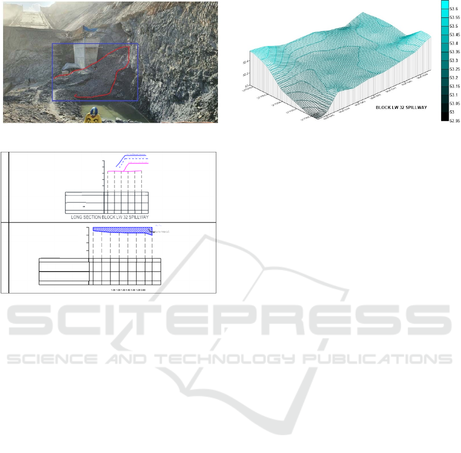
Figure 8: Counterweight installation.
Figure 9: Situation profile of the spillway block LW 32 LW.
The elevation of the cast top floor of the LW 32
block is at +54.00 m. The highest excavation
elevation is +53.60 m with a difference in height
difference of 0.40 meters from the elevation of the top
cast, for the lowest elevation at +52.95 m with a
difference of 1.05 meters from the top cast elevation.
The volume of casting on the LW 32 Block's work
floors was 22,345 m
3
.
Based on Figure 10, it can be seen the
visualization of the 3d grid showing the situation of
the LW 32 Block excavation surface. The results of
excavation show that various elevations are caused by
soil surface geological factors. The number of
working floor blocks in this study was 15 blocks, total
volume from excavation to the work floor elevation
was 505,609 m
3
, and the highest volume was in the
LW 35 Spillway block of 63,854 m
3
.
Figure 10: 3D grid viewing block LW 32 spillway.
3.4 Field Survey in Wall Structure
In the implementation of the building, structure work
is done in stages, usually, the work on the structure is
done by dividing it into several segments. The
Ladongi Dam damper structure works are separated
into 4 segments. Segment 1 is at an elevation of
+55.00 m, segment 2 is at an elevation of +56.00 m,
segment 3 is at an elevation of +64.50 m, and segment
4 is at an elevation of +67.50 m. The segmentation is
carried out to simplify the process of ironing,
installing formwork, and also the process of casting
the building structure.
In the excavation and also the structure work of
the energy-absorbing building walls, landslides occur
around the LW 33, LW 34, and LW 35 blocks. The
existence of landslides is caused by geological factors
in the area and the potential for landslides on the slope
above the building plan structure. The consequence
of the landslide occurred, dental fillings and/or
casting were carried out to cover the landslide area,
so that the original concrete requirements according
to the plan based on the design of the drawing were
calculated to the total volume of landslides. In
calculating the volume of the landslide, the survey
team had to measure the situation of the landslide
area. This measurement was using meters by
measuring the distance between the edge of the
building structure and the area affected by landslides.
In collecting the landslide data at block LW 34
Spillway, it was carried out by dividing it into 5
crosses starting from the 0 meters from the first block
and the interval distance for each cross is 2.5 meter,
the landslide cross measurements can be seen in
Figure 11.
Application on Survey Implementation of Dredging and Structure for Energy Reducing Spillway Building at Ladongi Dam
45
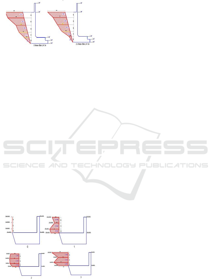
Figure 11: Cross landslide measurement block LW 34.
Dental casting for the LW 34 Spillway Block
Avalanche area is divided into 5 segments, namely
Dental 1, Dental 2, Dental 3, Dental 4, and Dental 5.
Segment Dental 1 is at an elevation of +54.00 m to an
elevation of +56.00 m, Segment dental 2 is at
elevation +56.00 m to an elevation of +57.71 m,
Segment dental 3 is at an elevation of +57.71 m to an
elevation of +60.11 m, Segment dental 4 is at an
elevation of +60.11 m to an elevation of +62.54 m,
and the segment dental 5 is at an elevation of +62.54
m up to +64.50 m elevation. The dental volume for
casting the landslide area of the LW 34 Spillway
Block was 347,959 m
3
.
The location of the energy reducing structure is
right under the slope of zone 3 spillway, and there was
a landslide right to the building structure on Block
LW 33 to Block LW 35 (El. +64.5 - El. +67.5). To
prevent further landslides in the slope area that can
affect structural damage and hinder other work, so to
prevent further landslides and establish the structure,
patching of the landslide area is carried out using
dentals. Cross landslide measurements are carried out
starting from the LW 33, LW 34, and LW 35 blocks
together. The number of crosses is 22 crosses and
starting from the first 0 meters of LW 33 Spillway
Block, and with 1-meter intervals between each cross,
the results of cross landslide measurements can be
seen in Figure 12.
Figure 12: Cross Landslide Block LW 33, 34, 35 (+65.21 -
+67.45).
Dental casting for the landslide area LW 33 Block
– LW 35 Spillway Block is divided into 3 segments,
namely Dental 1, Dental 2, and Dental 3. Segment
Dental 1 is at an elevation of +64.50 m to an elevation
of +65.21 m, and segment Dental 2 is at elevation +
65.21 m to an elevation of +66.38 m, the Dental 3
segment is at an elevation of +66.38 m to an elevation
of +67.45 m. The volume of LW 33, LW 34, and LW
35 Spillway block dental casting is 164,945 m3. The
total volume of additional landslide structures is
893,329 m
3
.
4 CONCLUSIONS
Handling of landslides is done by installing
counterweights in areas affected by landslides, and
those have the potential for landslides. The results
from the excavation situation measurement are used
to calculate the volume of the work floor casting
using the Mean Area equation. The total excavated
volume of elevation of the work floor is 505,609 m
3
.
The LW 33 Block dental volume is 138.99 m3
starting from +60.11 elevation to +64.50 elevation. In
Block LW 33 there was a landslide in zone 3 slopes
parallel to the structural parapet (El. + 64.5 - El. +
67.5) then dental filling was made, the total dental
volume needed was 164,954 m
3
.
ACKNOWLEDGEMENTS
The authors would like to thank all the Ladongi Dam
Project parties to the Balai Wilayah Sungai Sulawesi
IV Kendari, especially the Consultants PT Binatama
Wirawreda - PT Arga Pasca Rencana, KSO and
Contractor Hutama Karya – Bumi Karsa, KSO. They
have permitted and facilitated all efforts in data
collection.
REFERENCES
Adi, W. T., Aghastya, A, 2017. Penggunaan total station
dan autocad civil 3D untuk perencanaan grading.
Jurnal Perkeretaapian Indonesia.
Asiyanto, I, 2011. Metode Konstruksi Bendungan, Penerbit
Universitas Indonesia (UI-Press). Jakarta.
Frick, I., Heinz, 1984. Ilmu dan alat ukur tanah, Penerbit
Kanisius. Semarang.
Kustarto, D. H., 2012. Ilmu ukur tanah metode dan
aplikasi: bagian kedua, Penerbit Dioma. Malang, 1
st
edition.
ICAE 2020 - The International Conference on Applied Engineering
46

Kusuma, R. C., 2014. Evaluasi Desain Tahap 1 Disposal
Swd 11 Pit.
Masrul, Anjasmara, I. M., 2015. Pemantauan penurunan
muka tanah di kawasan Watukosek menggunakan
metode sipat datar, Geoid.
Maulidin, R. F., 2016. Studi penentuan volume dengan total
station dan terrestrial laser scanner, Institut Teknologi
Sepuluh Nopember.
Muda, I., 2008. Teknik Survei dan Pemetaan, Direktorat
Pembinaan Sekolah Menengah Kejuruan. Jakarta.
Prastumi, 2012. Pengaruh variasi tipe peredam energi
terhadap karakteristik hidrolika saluran pelimpah
bendungan studi kasus uji model pelimpah bendungan
Jehem—Bali, Rekayasa Sipil, pp. 153- 160.
Program Studi Teknik Geologi Tambang Batubara Distrik
Baya Desa Separi, Kecamatan Tenggarong Seberang,
Kabupaten Kutai Kartanegara, Kalimantan Timur.
Geological Engineering E-Journal.
Ratnawati, H., 2009. Pelimpah bertangga sebagai peredam
energi pada kolam olak tipe solid roller bucket,
Universitas Muhammadiyah Surakarta.
Sosrodarsono, D. I., 1977. Bendungan type urugan, PT.
Balai Pustaka (Persero). Jakarta, 4
th
edition.
Sosrodarsono, D. I., 2016. Bendungan Urugan, PT. Balai
Pustaka (Persero). Jakarta, 6
th
edition.
Susetyo, D. B., Tri, H., Saputra, L. R., 2013. Standarisasi
Aplikasi Survey Pemetaan Terestris Dalam Bidang
Konstruksi Struktur Bawah Bangunan.
TS-04, M., 2011. Melakukan stake out dan monitoring:
materi pelatihan berbasis kompetensi sektor konstruksi
sub sektor bangunan gedung.
Wijayanto, H., Sunarjono, S., Abdurrosyid, J., 2013.
Pengaruh Ketelitian Hasil Pengukuran Topografi
Terhadap Desain Irigasi Gonggang, Universitas
Muhammadiyah Surakarta.
Application on Survey Implementation of Dredging and Structure for Energy Reducing Spillway Building at Ladongi Dam
47
