
Trajectory Tracking and Formation Control of Multiple Mobile
Robot based on Leader Follower Approach: Comparing Constant
and Non-constant Velocity of the Leader
M. Latif
1
and Sri Herawati
2
1
Department of Mechatronics Engineering, University of Trunojoyo Madura, Bangkalan, Indonesia
2
Department of Information Systems,University of Trunojoyo Madura, Bangkalan, Indonesia
Keywords: formation control, tracking trajectory, leader follower, mobile robot.
Abstract: Formation control with leader follower approach and tracking trajectory with comparing constant and non-
constant velocity of the leader is proposed in this paper. Non-constant velocity aim to solve the problem of
time requirement to achieve asymptotic tracking error in velocity constant issue of the leader. Controller is
designed based on mobile robot kinematics model. Mobile robot used similar type of model and
characteristics. Trajectory information used to control the leader's velocity. Position and velocity of the
leader used to determine the follower movement velocity. Follower tracks the virtual position to make a
rigid formation. The experiment was carried out using two scenarios. First, leader moves linearly toward a
destination point, second, leader moves along a circular trajectory. Each scenario analyzed and compared
between constant and non-constant velocity of the leader. The experimental results show leader's velocity
with a non-constant value has a slightly slower than constant velocity to achieve formation error that is close
to zero. However, the leader's velocity with a non-constant value has a faster time to achieve tracking
trajectory error that is close to zero.
1 INTRODUCTION
Formation control of mobile robot is one of the
many research topics currently conducted. That is
because of its ability to perform complex tasks with
high efficiency and reliability. A rescue mission,
moving large objects, hunting, forming a satellite
formation and clustering is too difficult or
impossible for a single robot. Formation controls are
also used in completing agricultural task (Cartade et
al., 2004), supervisory assignment (Tang and
Özgüner, 2005) and transportation (Loianno and
Kumar, 2018). The main purpose of formation
control is to move to follow the trajectory and
maintain the formation. Formation controls have the
challenge that each agent usually cannot rely on
centralized coordination and must use local
information to achieve the desired formation. The
category of formation control is divided into
centralized (De la Cruz et al., 2006) and
decentralized (Li, Er and Zhang, 2017). It is
centralized if all controls and monitors are
performed by a centralized processor. Decentralized
when all robots have local control over the task.
There are several strategies to implemented the
formation control of a group of mobile robots, e.g.,
behaviour-based control (Droge, 2015), virtual
structure (Cao and Liu, 2012), leader-follower
(Loria, Dasdemir and Alvarez Jarquin, 2016,
Ghamry and Zhang, 2015), relative position-based
(Dimarogonas and Kyriakopoulos, 2008), artificial
potentials field (Ying and Xu, 2015) and graph
theory (Han et al., 2012).
One of the most popular formation controls is the
leader follower approach. The approach consists of
one robot as a leader and some robots as followers.
For example, there is one robot as a leader following
a trajectory and then another robot as a follower who
follows a leader with a predetermined position and
orientation. The advantage of the leader follower
approach is the effectiveness in controlling a group
of mobile robots by simply assigning a single
trajectory to the leader only. Some previous research
on leader follower usually determines the velocity of
leader's movement constantly, for example by (Choi,
Choi and Chung, 2012). Experiments conducted
Latif, M. and Herawati, S.
Trajectory Tracking and Formation Control of Multiple Mobile Robot based on Leader Follower Approach: Comparing Constant and Non-constant Velocity of the Leader.
DOI: 10.5220/0010312103770383
In Proceedings of the International Conference on Culture Heritage, Education, Sustainable Tourism, and Innovation Technologies (CESIT 2020), pages 377-383
ISBN: 978-989-758-501-2
Copyright
c
2021 by SCITEPRESS – Science and Technology Publications, Lda. All rights reserved
377
using two robots, one as a leader and other as a
follower. The controller method used by the
follower is PID. In other studies that provide a
constant value to the leader is performed by (Li and
Xiao, 2005, Obayashi et al., 2017, Guo et al., 2017).
The issue in the trajectory tracking and formation
control problem by setting the leader's velocity
constantly is need a longer time to reach the
asymptotic tracking error.
Formation control with leader follower approach
and tracking trajectory with comparing constant and
non-constant velocity of the leader is proposed in
this paper. Non-constant velocity aim to solve the
problem of time requirement to achieve asymptotic
tracking error in leader velocity constant issue.
Trajectory information is used to control leader's
velocity, position and leader's velocity used to
control follower’s movement velocity. Follower will
tracks a predetermined virtual position to form a
formation, while the leader tracks a point or
trajectory. Direct kinematic used to control design
and implemented to all robots. The objective to be
achieved in this research is to generate optimal time
to achieve asymptotic tracking error, either
formation error or trajectory tracking error.
2 ROBOT MODEL
In this section the mobile robot dynamics and
kinematics models based on the research by (De la
Cruz et al., 2006) are described. Type of mobile
robot use differential drive. The movement of a
mobile robot wheeled is influenced by the
movement of each wheel. Mobile robot used in this
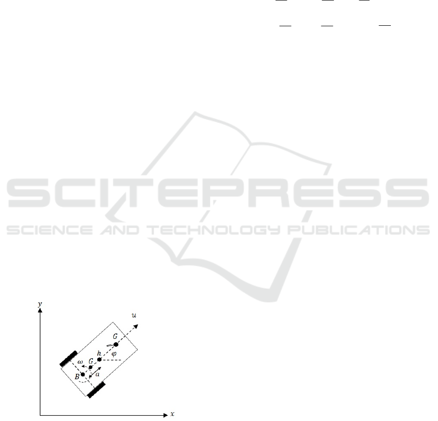
research is illustrated as in Figure 1.
Figure 1. Model of mobile robot
u and ω are linear and angular velocity; φ is
orientation of the mobile robot; α is distance
between center point of the wheel axis and local
coordinates; G is center of robot mass; B is center
point of the wheel axis; C is castor wheels; and h is
position robot in the global coordinate. The
mathematical model is completely written as;
0
1
cos
sin
0
sin
cos
y
x
u
y
x
(1)
u
r
r
u
u
u
u
...
...
1
0
0
1
2
1
2
6
2
5
1
4
2
1
3
(2)
T
654321
(3)
T
uyx
0
(4)
Equation (1) is a kinematics model and (2) is a
dynamics model of the mobile robot. Equation (3) is
a vector of identified parameter and (4) is an
uncertainty parameter that occurs in the robot while
movement. Varible θ is related to physical robot and
refers to the research conducted by (Martins et al.,
2008). Variable δ
x
, δ
y
are slip velocity and
orientation functions of the mobile robot, while δ
u,
δ
ω
is a physically caused disturbance function such
as mass, inertia, wheel and tire diameters, motor and
servos parameters, power on wheels, and others .
Parameter δ is a disturbance that occurs and affects
the movement of the mobile robot.
3 LEADER-FOLLOWER
FORMATION CONTROL
In the leader follower approach, agent or robot is
divided into two types of roles, i.e. one role as leader
and the other as follower. To form and maintain the
formation, follower must know position to the
leader. Follower must always keep the distance and
angle error of the leader equal to zero, in other
words, robot must always go to the specified
reference point (x
dF
, y
dF
). Reference point is always
rigid to leader, and are called as a virtual position.
Illustration of leader follower approach shown as
Figure 2, where dist
r
and θ
r
are distance and angle
reference respectively; (x
L
, x
L
) is currentt position of
CESIT 2020 - International Conference on Culture Heritage, Education, Sustainable Tourism, and Innovation Technologies
378
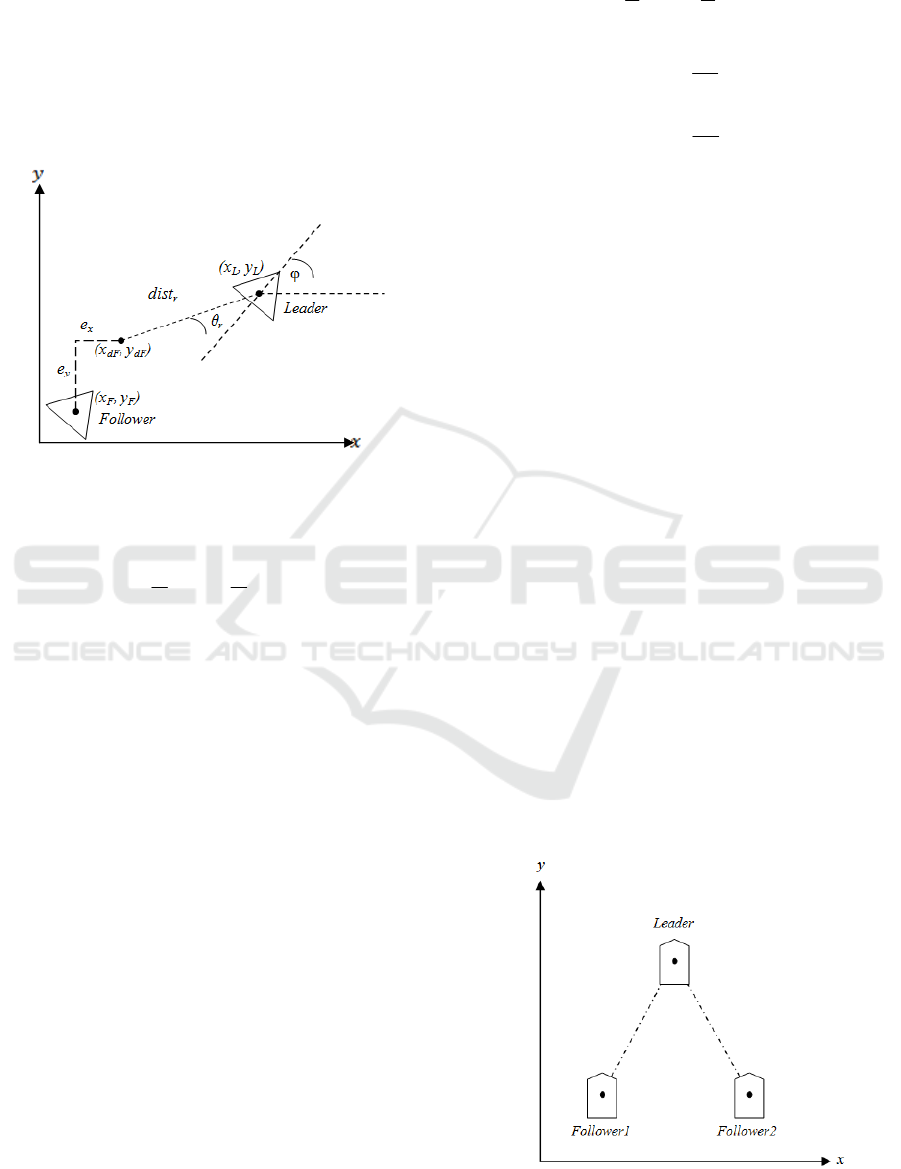
the leader; φ is heading of the leader, (x
dL
, x
dL
) is
position reference of the follower; (x
F
, x
F
) is current
position of the follower; and e
x
and e
y
position error
in x and y axis respectively. Based on Figure 2,
distance reference and angle reference can be
defined in Equation (5) and (6), respectively, and
virtual position can be obtained using Equation (7)
and (8).
Figure 2. Leader follower model
0
r
dist
(5)
22
r
(6)
)))cos(*((
rFLrLdF
distxx
(7)
)))sin(*((
rFLrLdF
distyy
(8)
4 CONTROL DESIGN
Motion control is designed based on the kinematic
model of mobile robot. Type of decentralized
control is used in this study, so each mobile robot
use local control. Assuming there is no slip on the
wheel and a disruption to the robot dynamics, the
kinematic equation is written as follows;
u
y
x
1
cos
sin
0
sin
cos
(9)
Assuming the specifications of all robots are
similar, then the control laws proposed for all mobile
robots are written in Equation (10).
i
i
y
y
y
yd
x
x
x
xd
i
i
e
s
k
sy
e
s
k
sx
aa
u
tanh
tanh
...
...
cos
1
sin
1
sincos
(10)
Where;
dd
yx
, is desired velocity, (e
xi
, e
yi
) the
position error, (k
x
, k
y
) is gain controller where k
x
> 0
and k
y
> 0, (s
x
, s
y
) ) is saturation of the robot; (x
d
, y
d
)
is desired position; (x
i
, y
i
) is current position of the
robot; and i is index of the robot. Distance error on
the x and y axis is calculated using Equation (11)
and (12), respectively.
idx
xxe
ii
(11)
idy
yye
ii
(12)
5 EXPERIMENTAL RESULTS
Experiments conducted to verify and determine the
effectiveness of the control design. Experiments uses
three mobile robots and the desired formation is a
triangular shape as shown in Figure 3. The robot
parameters used in the experiment are shown in
Table 1. Experiment is comparing constant and non-
constant velocity of the leader while perform
formation and tracking trajectory. The experiments
were conducted in two scenarios. First, leader moves
linearly to a specified point. Second, leader
following a circular trajectory.
Figure 3. Triangular shape formation
Trajectory Tracking and Formation Control of Multiple Mobile Robot based on Leader Follower Approach: Comparing Constant and
Non-constant Velocity of the Leader
379
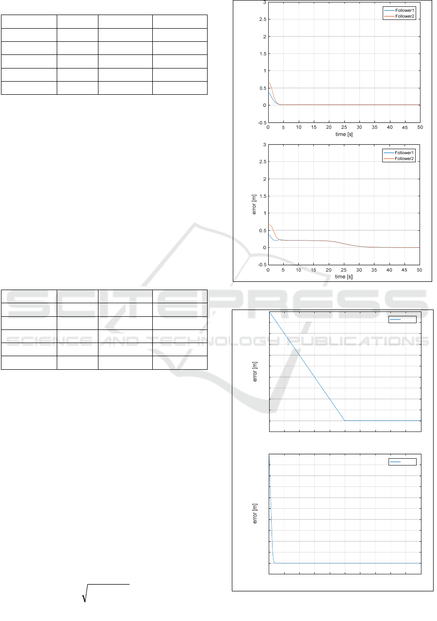
Table 1: Parameters of the mobile robot
Paramete
r
Leade
r
Follower1 Follower2
k
x
0.5 0.5 0.5
k
y
0.5 0.5 0.5
s
x
0.4 0.4 0.4
s
y
0.4 0.4 0.4
α 0.2
m
0.2
m
0.2
m
5.1 Linear Movement
In this scenario, the leader is moves to the specified
point, and then the follower moves to construct a
predetermined formation. Destination point of the
leader is x=6 and y=0. Initial position of each robot
has not yet formed a triangle formation. The initial
values of the positions of each robot and the
formation parameters are shown in Table 2. The
leader's velocity with constant value is 0.01 m/s. For
simplicity, we agree that a is leader's velocity with
constant value and b is leader's velocity with non-
constant value or leader's velocity with controller
value.
Table 2: Initial position and formation parameters
Paramete
r
Leade
r
Follower1 Follower2
x initial 1 0.5 0
y
initial 0 0 0.5
φ initial 0 0 0
dist
r
- 0.5
m
0.5
m
θ
rF
- 0.785 ra
d
-0.785 ra
d
In the linear movement experiments, formation
error of a is more faster than b to close to zero as
shown in Figure 4. In the Figure, a is constant
velocity and b is non-contant velocity of the leader
repectively. The steady state error of the robot
during make a formation has close to zero in s = 4 in
a, whereas in b close to zero in s = 32. Formation
error for each follower is obtained using (13).
Tracking gol position error with a non-constant
velocity of the leader more faster than constant
velocity to close to zero as shown in Figure 5.
Steady-state error of tracking gol position occurred
at s = 500 in a, whereas in b occurred at s = 40. The
experiment shows that in a, formation is faster to
rigid, but takes longer time to reach destination
point. In otherwise, a need longer time to reach rigid
formation, but a faster to get to the destination
22
yx
eedist
(13)
a
b
Figure 4. Formation error
a
b
Figure 5. Tracking goal position error
error [m]
0 100 200 300 400 500 600 700 800 900 1000
time [s]
-0.5
0
0.5
1
1.5
2
2.5
3
3.5
4
4.5
5
g
Leader
0 100 200 300 400 500 600 700 800 900 1000
time [s]
-0.5
0
0.5
1
1.5
2
2.5
3
3.5
4
4.5
5
g
Leader
CESIT 2020 - International Conference on Culture Heritage, Education, Sustainable Tourism, and Innovation Technologies
380
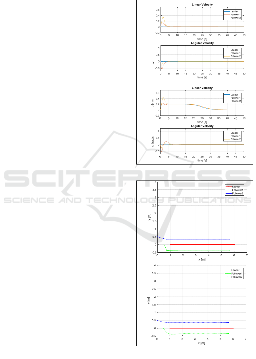
The linear and angular velocities of each robot
are shown in Figure 6, whereas the robots trajectory
are shown in Figure 7. Linear velocity each follower
of a and b close to leader in s =4. Angular velocity
of a close to the leader in s=5, b close to the leader
in s=7. b before reaching steady state in linear
velocity, there is an overshoot at s = 2 for follower1
and at s=3 for follower2. Angular velocity in b,
before reaching steady state, there is an overshoot at
s = 4 for follower2 and at s=3 for follower2.
5.2 Trajectory Tracking
In the second scenario, the leader's movement is
controlled to follow the circle trajectory. While
leader moves to follow trajectory, follower is
controlled to formed a triangle formation. The initial
position of each robot used first scenario experiment
parameters. Initial position values of each robot and
formation parameters are shown in Table 2. The
leader's velocity value is 0.01 m/s for experiments
with leader having constant values.
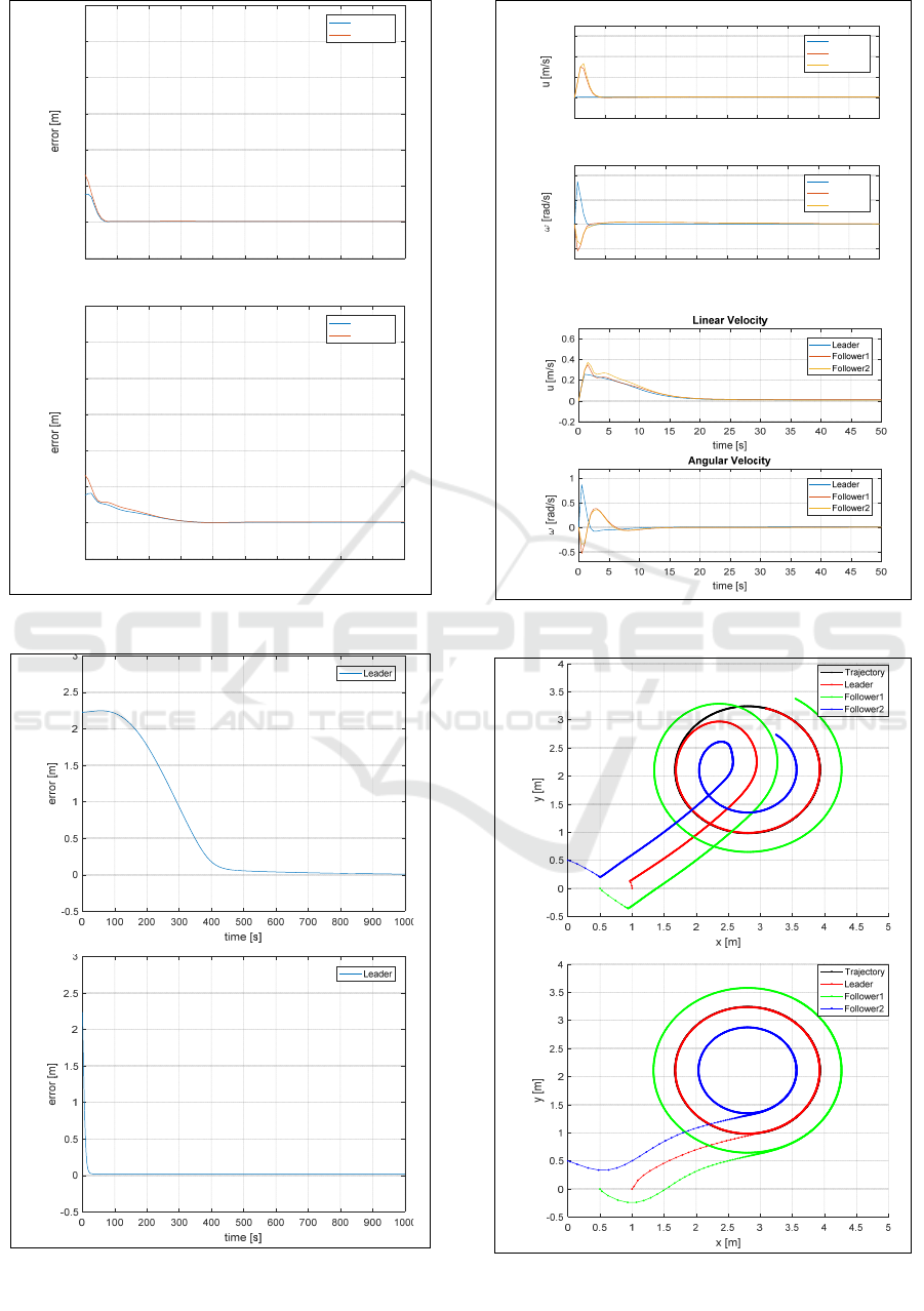
According to this experiment, formation errors of
each follower converge to zero at s = 4 in a, while b
close to zero at s =16. The trajectory tracking errors
has close to zero at s = 40 and at s =800 for a and b
respectively. This indicates that the formation has
been more quickly achieved if the leader is given
constant velocity, but trajectory tracking error is
very slow close to zero. whereas in b, formation is
established slowly, but trajectory tracking error is
faster close to zero. Comparison of distance error
during the formation established in this experiment
is shown in Figure 8, while the comparison of
trajectory tracking error is shown in Figure 9.
The linear and angular velocity of each robot are
shown in Figure 10. Linear velocity of a close to
leader in s =4, while b in s=20. Angular velocity of a
close to the leader in s=31, b close to the leader in
s=15. b before reaching steady state in linear
velocity, there is an overshoot at s = 2 for follower1
and follower2. After the overshoot, follower2 is
slower than follower1 to reach steady state. Angular
velocity in b, before reaching steady state, there is an
overshoot at s = 4 for follower1 and follower2. Since
s = 2, angular velocity of all followers has the same
value.
Figure 11 shows the trajectory of leader and
followers in the second experiment. In this
experiment, it can be seen that the robot formation
with leader follower approach is rigidly.
a
b
Figure 6. Linear and angular velocity of the robot
a
b
Figure 7. Trajectory of the robot
u [m/s]
[rad/s]
Trajectory Tracking and Formation Control of Multiple Mobile Robot based on Leader Follower Approach: Comparing Constant and
Non-constant Velocity of the Leader
381
a
b
Figure 8. Formation error
a
b
Figure 9. Tracking trajectory error
a
b
Figure 10. Linear and angular velocity of the robot
a
b
Figure 11. Trajectory of the robot
0 5 10 15 20 25 30 35 40 45 50
time [s]
-0.5
0
0.5
1
1.5
2
2.5
3
Follower1
Follower2
0 5 10 15 20 25 30 35 40 45 50
time [s]
-0.5
0
0.5
1
1.5
2
2.5
3
Follower1
Follower2
0 5 10 15 20 25 30 35 40 45 50
time [s]
-0.2
0
0.2
0.4
0.6
Linear Velocity
Leader
Follower1
Follower2
0 5 10 15 20 25 30 35 40 45 50
time [s]
-0.5
0
0.5
1
Angular Velocity
Leader
Follower1
Follower2
CESIT 2020 - International Conference on Culture Heritage, Education, Sustainable Tourism, and Innovation Technologies
382

6 CONCLUSIONS
Experiments on formation control with leader
follower approach and tracking trajectory by a group
of mobile robot were performed with two scenarios.
The experiment also compared the results between
the constant and non-constant leader velocity. The
formation used in the experiment is a triangular
shape. The experimental results show that the leader
with non-constant velocity has a slower than that of
the constant velocity to established formation, i.e. at
s = 32 and s = 4 for the first scenario, and s= 16 and
s = 4 for second scenario, respectively. However, the
leader with non-constant velocity has a faster to
achieve trajectory tracking error close to zero, i.e., s
= 40 and s = 500 for the first scenario, and s = 40
and s = 800 for second scenario, respectively. In the
future research, experiments can be implemented to
robots that work in 3D plane like quad-rotor.
REFERENCES
Cao, K. and Liu, C., 2012. Formation tracking control and
formation stabilization control of multiple
nonholonomic mobile robots. In Control Conference
(CCC), 2012 31st Chinese, pp. 6053–6058.
Cartade, P. et al., 2004. Motion Control of a
heterogeneous fleet of mobile robots : Formation
control for achieving agriculture task. In AGENG
2012 5th Automation Technology for Off-Road
Equipment Conference, pp. 2–7.
Choi, I. S., Choi, J. S. and Chung, W. J. (2012. Leader-
follower formation control without information of
heading angle. In 2012 IEEE/SICE International
Symposium on System Integration, SII 2012, pp. 842–
846.
Dimarogonas, D. V. and Kyriakopoulos, K. J., 2008. A
connection between formation infeasibility and
velocity alignment in kinematic multi-agent systems.
Automatica, 44(10), pp. 2648–2654.
Droge, G., 2015. Distributed virtual leader moving
formation control using behavior-based MPC. In
Proceedings of the American Control Conference, pp.
2323–2328.
Ghamry, K. A. and Zhang, Y., 2015. Formation control of
multiple quadrotors based on leader-follower method.
In 2015 International Conference on Unmanned
Aircraft Systems, ICUAS 2015, pp. 1037–1042.
Guo, D. et al., 2017. A unified leader-follower scheme for
mobile robots with uncalibrated on-board camera. In
Proceedings - IEEE International Conference on
Robotics and Automation, pp. 3792–3797. doi:
10.1109/ICRA.2017.7989438.
Han, Z. et al., 2012. Double-graph formation control for
co-leader vehicle networks. In Proceedings of the
2012 24th Chinese Control and Decision Conference,
CCDC 2012, pp. 158–163.
De la Cruz, C. et al., 2006. Dynamic Modeling and
Centralized Formation Control of Mobile Robots. In
IEEE Industrial Electronics, IECON 2006 - 32nd
Annual Conference on, pp. 3880–3885.
Li, S., Er, M. J. and Zhang, J., 2017. Distributed Adaptive
Fuzzy Control for Output Consensus of
Heterogeneous Stochastic Nonlinear Multi-Agent
Systems. IEEE Transactions on Fuzzy Systems,
PP(99), pp. 1–1.
Li, X. and Xiao, J., 2005. Robot Formation Control in
Leader-Follower Motion Using Direct Lyapunov
Method. International Journal of Intelligent Control
and Systems, 10(3), pp. 244–250.
Loianno, G. and Kumar, V., 2018. Cooperative
Transportation using Small Quadrotors. IEEE
Robotics and Automation Letters, 3(2), pp. 680–687.
Loria, A., Dasdemir, J. and Alvarez Jarquin, N., 2016.
Leader-Follower Formation and Tracking Control of
Mobile Robots Along Straight Paths. IEEE
Transactions on Control Systems Technology, 24(2),
pp. 727–732.
Martins, F. N. et al., 2008. An Adaptive Dynamic
Controller for Autonomous Mobile Robot Trajectory
Tracking. Control Engineering Practice, 16, pp. 1354–
1363.
Obayashi, M. et al., 2017. Leader-Follower Formation
Control Using Cerebellar Perceptron Improved Model
with Auto-structuring. In Proceedings - 19th IEEE
International Conference on Computational Science
and Engineering, 14th IEEE International Conference
on Embedded and Ubiquitous Computing and 15th
International Symposium on Distributed Computing
and Applications to Business, Engi, pp. 423–431.
Tang, Z. and Özgüner, Ü., 2005. Motion Planning for
Multitarget Surveillance. IEEE Transactions on
Robotics, 21(5), pp. 898–908.
Ying, Z. and Xu, L. I., 2015. Leader-follower Formation
Control and Obstacle Avoidance of Multi-robot Based
on Artificial Potential Field. In Control and Decision
Conference 2015, pp. 4355–4360.
Trajectory Tracking and Formation Control of Multiple Mobile Robot based on Leader Follower Approach: Comparing Constant and
Non-constant Velocity of the Leader
383
