
On the Potential of Distance Bounding based on UWB Received Signal
Strength
Leo Botler
1 a
, Leandro Batista Ribeiro
1 b
, Konrad Diwold
1,2
and Kay R
¨
omer
1 c
1
Institute for Technical Informatics, Graz University of Technology, Austria
2
Pro
2
Future, Austria
Keywords:
Distance Bounding, Distance Enlargement, UWB, Signal Strength, RSSI.
Abstract:
Distance bounding has gained attention in the last decades due to the increasing need for security in applica-
tions, such as contactless payment and keyless access control. In such applications, it is important to verify
if the two entities participating in a transaction are geographically close to each other. In other applications,
it is critical to guarantee that the two entities are not too close, e.g., human and machines interacting in the
same environment. A distance fraud is a known class of attacks in this context, and it has been shown that
particular attacks within this class can be successfully applied to any distance estimation approach relying
on round-trip time-of-flight measurements. In this paper we discuss the feasibility of detecting such attacks
with signal strength estimations, an approach which was deemed unsuitable for distance bounding by previous
related studies. We show that our method can detect attacks in case a dishonest prover does not respect the
given bounds by using path-loss models available in the literature.
1 INTRODUCTION
Distance bounding protocols (Avoine et al., 2018) are
currently applied in real-world system in order to en-
hance security in several applications including seam-
less access control and contactless payments. In both
of those, the goal is to verify whether the two entities
involved in a transaction are sufficiently close to or far
from each other. We refer to these entities as prover
(P) and verifier (V), in agreement with the literature.
Distance bounding protocols traditionally use the
fact that nothing can travel faster than the speed of
light to ensure that P and V are within a certain
distance. By timing the delay between transmitting
and receiving a signal back, V can estimate an upper
bound on its distance from P.
In the literature, distance-related attacks are com-
monly classified into 4 groups (Avoine et al., 2018):
impersonation, distance fraud, mafia fraud and terror-
ist fraud. In all of these groups, (at least) one external
adversary takes part in the protocol, except in the dis-
tance fraud, in which the prover is the dishonest entity
itself.
a
https://orcid.org/0000-0002-4683-2422
b
https://orcid.org/0000-0002-1294-1524
c
https://orcid.org/0000-0002-4248-4424
Establishing a lower bound has also been consid-
ered in the literature. A challenging attack in this
context is known as the Distance Enlargement Fraud
(DEF), in which a dishonest prover, i.e., a prover not
following the established protocol, claims to be at a
distance from the verifier further than it actually is.
It is feasible for the verifier to detect if the prover
is trying to perform the opposite attack, entitled Dis-
tance Reduction Fraud (DRF), as the prover cannot
(correctly, with a high probability) respond to a mes-
sage before having received it. However, to succeed
in the DEF, all the prover has to do is to introduce
a delay between its receiving and transmitting times-
tamps. This topic is discussed in detail in Section 2.
A different physical principle enabling distance
bounding relies on received signal strength (RSS)
measurements. This class of approaches is widely
used in localization systems and has barely been dis-
cussed in the related literature on distance bounding.
We hypothesize that this was motivated by the high
accuracy achieved with modern time-of-flight (ToF)-
capable transceivers and by the solid theoretical basis
provided by the pioneer works about distance bound-
ing; the vast majority of papers in the field relies on
ToF measurements. Still, many of those RSS systems
may also require physical-level security, and currently
there are still no means to provide it. In this paper
Botler, L., Ribeiro, L., Diwold, K. and RÃ˝umer, K.
On the Potential of Distance Bounding based on UWB Received Signal Strength.
DOI: 10.5220/0010282200070014
In Proceedings of the 10th International Conference on Pervasive and Parallel Computing, Communication and Sensors (PECCS 2020), pages 7-14
ISBN: 978-989-758-477-0
Copyright
c
2020 by SCITEPRESS – Science and Technology Publications, Lda. All rights reserved
7

we address this gap and aim to show that there may
be other physical-level possibilities enabling distance
bounding with a security level comparable with the
one achieved with ToF measurements. In particular,
we aim to find bounds for distance frauds using RSS
measurements only.
Another obstacle in exploring security within RSS
is the low accuracy estimations achieved with this ap-
proach, usually in the order of meters (Zafari et al.,
2017). Large errors are predominant indoors, where
multipath interference makes the measurements un-
stable. This issue is less severe within the Ultra-
wideband (UWB) technology, in which the high time
resolution enables the receiver to separate the first in-
coming path from the reflected signals, reducing the
influence of the environment on path loss. We account
for such instabilities in the validation of our method
using models available in the literature.
The contributions of this paper are:
• We propose a RSS-based distance-bounding pro-
tocol enabling protection against distance frauds
and compare its strengths and weaknesses with
state-of-the-art approaches;
• We determine the bounds achieved by this pro-
tocol against distance reduction and enlargement
frauds, which are independent on time measure-
ments. To the best of our knowledge, no bounds
have been proposed before for RSS measure-
ments;
• We show that signal strength measurements,
thought to be of no use to distance bounding pro-
tocols so far, can enhance and be a useful building
block to distance bounding protocols;
• We evaluate the security level provided by the pro-
posed approach using real-world measurements
available in the literature.
2 RELATED WORK
This section focuses on the distance fraud. For a de-
tailed overview about distance bounding, we refer the
reader to (Zafari et al., 2017).
In (Singh et al., 2019) the authors consider en-
largement attacks, but within a different class, namely
mafia fraud. In this attack
1
, one or several entities po-
sitioned in between V and P, try to convince V that
P is in a different location than it actually is. In this
specific case, the attacker’s goal is to convince V that
P is further away than it really is. In this attack, P
is honest and acts according to the protocol it must
1
We refer to a fraud as a particular case of an attack.
follow, while the attacker, an external malicious en-
tity, manipulates the signals exchanged. The distance
frauds (DF), considered in this paper, differ from the
mafia fraud as there is no malicious attacker involved;
P is the malicious entity itself. This constitutes a ma-
jor challenge in two-way ranging (TWR)-based ToF
measurements, since P successfully performs an en-
largement fraud by simply delaying its acknowledge-
ment upon a request from V.
In (Capkun and Hubaux, 2005), the authors dis-
card the possibility of using the received signal
strength for distance bounding without a detailed dis-
cussion. The authors claim that P can succeed in
a distance fraud by claiming a different power level
than it actually received. In this paper, we show that
this statement is true for single-verifier single-antenna
systems, but that in general there are bounds to the
magnitude of the attack.
In the same paper, the authors propose a
technology-agnostic solution to enlargement frauds.
The solution works as long as P is within a trian-
gle formed by N = 3 verifiers, which is the minimum
number of trusted entities required for the system to
work. For a successful DEF to one of the verifiers,
P must simultaneously perform a DRF to at least one
other verifier. As the system is secured against DRF
using traditional distance bounding protocols, this is
impossible. However, the attack cannot be detected
if P is outside the triangle. Another weakness of this
approach consists in the number of verifiers required.
In this paper we analyze other possibilities with N = 1
and N = 2.
In the rest of this section, we discuss the vulnera-
bility of ToF-based measurements.
2.1 Distance Bounding based on ToF
We start by considering a single verifier and a sin-
gle prover in our system. The goal for P is to find a
good strategy to succeed in a DEF, while the goal for
V is to detect such an attack. The approach is DEF-
resilient if V is able to detect the fraud or to bound
P’s pretended position from its real position. If the
system relies on TWR ToF estimations, P always suc-
ceeds (Zheng et al., 2014), i.e., there is a strategy for
P to follow for which the attack cannot be detected.
All P has to do is to increase its processing delay by
a constant amount.
The linear relation between the processing delay
and the apparent distance allows P to always succeed
in the fraud and accurately determine the absolute
value of the enlargement desired. The distance (d)
between V and P can be calculated by V in a TWR
protocol as in Equation 1
PECCS 2020 - 10th International Conference on Pervasive and Parallel Computing, Communication and Sensors
8

Figure 1: Two verifier’s system. Each circle is centered on
the position of a different verifier and has as radius the dis-
tance estimated to P. P can increase its distance to both the
verifiers using always the same processing delay and still
appear to be further than it really is to both of the verifiers
(red arrow). The position is plausible as the circles always
intercept in two points.
d =
1
2
·(t
V,rx
−t
V,tx
−∆
Proc
0
) ·c (1)
where t
V,rx
and t
V,tx
are the verifier’s RX and TX
timestamps, respectively, ∆
Proc
0
is P’s predetermined
processing time and c is the speed of light. ∆
Proc
0
can
alternatively be communicated to V via instant times-
tampings from P. To see how the increase in P’s ac-
tual processing time (∆
Proc
) increases d, we re-write
Equation 1 substituting t
V,rx
by t
V,tx
+ 2 ·t
f
+ ∆
Proc
,
which leads to
d =
1
2
·(t
V,tx
+ 2 ·t
f
+ ∆
Proc
−t
V,tx
−∆
Proc
0
) ·c
=
1
2
·(2 ·t
f
+ ∆
Proc
−∆
Proc
0
) ·c (2)
where t
f
is the time-of-flight. From Equation 2, the
linear relation between ∆
Proc
and d becomes clear. A
constant increase in distance can be achieved by P in-
dependent of its actual distance from V.
Considering N = 2 verifiers in the system, as long
as the 2 verifiers and P are not collinear, there will al-
ways be 2 intersections for the circles which have the
verifiers as centers and the apparent distance between
a given verifier and P as radius. If the circles have at
least one intersection, no fraud can be detected, and
therefore, the position of P - and also the apparent
distances - cannot be detected as fraudulent. Such a
fraud is sketched in Figure 1. Although the position
is ambiguous, as there are always two intersections,
we are interested only in verifying the distance from
the verifiers. A third verifier is commonly inserted to
remove this ambiguity in localization systems.
If N = 3 and P is within the triangle formed by
the verifiers, the DEF is no longer valid, because the
intersection of the three distance estimations will not
exist, creating evidence for the attack. Additionally,
it is assumed that performing a distance reduction at-
tack is not possible, i.e., the verifiers already imple-
ment a traditional distance bounding protocol, such
as the one proposed in (Brands and Chaum, 1993),
which protects from it. Therefore, P cannot reduce
its apparent distance from any of the verifiers. This
is the principle for the technique known as verifiable
multilateration (Capkun and Hubaux, 2005).
3 SYSTEM AND ATTACK MODEL
The system considered in this paper consists of a
set of N verifiers (V ) (devices with known locations
- known also to the prover if not stated otherwise)
which aim to estimate their distance from a dishon-
est prover (P) by using RF measurements. P’s goal
is to convince the verifiers that it is at a distance dif-
ferent than it really is from one verifier. There are
no adversaries in the environment, besides P itself.
The signals’ exchange in the protocol occurs in a short
window of time, and thus the quasi-stationary regime
is assumed; all the nodes are static. P is not capa-
ble of estimating the Direction-of-Arrival (DoA) of
the incoming signals
2
. The case for which P is DoA-
capable will also be discussed in Section 4. P may not
respect federal limits or laws and may have a better
hardware than the verifiers, that, for instance, enables
it to successfully demodulate signals sent at a lower
Signal to Noise Ratio (SNR). The verifiers, if more
than one, are free to communicate among each other
over a secure channel. They can transmit signals us-
ing a finite, bounded and discrete set of transmission
powers. For P, we can assume that this set is infinite,
unbounded (but non-negative) and continuous. Addi-
tionally, P knows the set available to V.
4 DISTANCE BOUNDING BASED
ON SIGNAL STRENGTH
In this section we discuss some possibilities of using
signal strength measurements as a building block for
distance bounding protocols.
2
This constitutes an important limitation of the proposed
approach, as DoA capable transceivers exist, in particu-
lar for UWB. However, their practical relevance is limited
due to high hardware overhead (i.e., multiple antennas +
transceivers).
On the Potential of Distance Bounding based on UWB Received Signal Strength
9

4.1 Distance Bounding based on Signal
Strength
Assuming the log-distance path loss model for power
decay over distance, the power P
rx
measured by a re-
ceiver equals
P
rx
= P
tx
·C ·
1
d
γ
(3)
where γ is the path loss exponent, and C is a con-
stant. In realistic indoor environments, the path-loss
exponent is typically 6= 2 and is highly dependent on
the environment due to multipath propagation. With
UWB, however, due to the short pulses, multi-path in-
terference is limited and we can expect a stable path
loss ≈ 2 as shown in (Rubio et al., 2013).
In order to test if P is honest, we initially con-
sider the following strategy: V transmits a sequence
of signals to P at different power levels, which are
chosen from a finite dictionary. P measures the sig-
nals’ strength and sends them back to V . V calculates
a distance d between V and P for each transmitted sig-
nal using Equation 3. V accepts the distance as true
if all distances are consistent. Obviously, an attacker
would manage to control its apparent distance to V
by multiplying P
rx
by a constant. Therefore, the basic
strategy considered does not work.
Nonetheless, if P does not know its distance to V ,
there are still bounds on how much P can increase
or decrease the measured distance by cheating on the
RSS. In this case, P must be careful when choosing
the size of the distance decrease/enlargement factor
(k). If P sends V a received power value P
0
rx
too high,
it may eventually exceed the transmitted power P
tx
,
and V detects the fraud. To be on a safe side, P
should always assume that P
tx
is the smallest power
level from the dictionary greater than P
rx
. Therefore,
k ≤
P
tx
next
P
rx
, where P
tx
next
is the smallest transmission
power from the dictionary greater than P
rx
.
Independent of the previous examined assump-
tion, if P performs a DEF, it is bounded by the min-
imum P
rx
that a honest prover would be capable to
receive. Therefore, k ≥
P
rx
min
P
rx
. Another approach can
be applied against the DEF. V sends a sounding mes-
sage to P to get a first estimation of its distance. Based
on this estimation, V adjusts P
tx
so that P
rx
= P
rx
min
,
i.e., the power level at P is the minimum that a hon-
est prover can successfully demodulate. V transmits
a nonce using P
tx
, which P must acknowledge. The
nonce keeps P from sending acknowledgments before
receiving the message. This approach does not work
in case P has a better hardware than a honest prover,
such as a more sensible low noise amplifier or a di-
rectional antenna. In this case P would still succeed
in the DEF.
Besides this intrinsic security flaw, this approach
should only work if the power level measurements are
reasonably stable within a given distance range, i.e.,
there is a deterministic mathematical model to which
the RSS measurements fit well. If the model does not
represent the actual behavior of the system (poor fit),
it is expected that V ’s estimations will, with a high
probability, differ from P’s distance. As a results, the
distance bounding system should present high false
positives and negatives ratios. We examine this issue
in Section 5.
4.2 Bounding Distance Reduction with
Two Verifiers
Regarding the Distance Reduction Fraud, the pro-
posed protocol can be adapted to be effective as
follows: (at least) two verifiers, each located at a
different position, transmit a signal to P, one at a
time, from the P
tx
dictionary. The sequence dictating
which verifier transmits at a certain time-slot can be
agreed among the verifiers beforehand using a secure
channel. For simplicity, we assume that the system
comprises only two verifiers, and that P intends to
perform a distance reduction attack against only one
of them. We refer to this verifier as V while we refer
to the other as V
aux
. V
aux
is positioned closer to P than
V . In a realistic scenario, V may be attached to an
object to be protected and V
aux
should be placed on
P’s path. In order to perform the DRF, P must claim
a higher P
rx
than it actually measured, which we call
P
0
rx
, in such a way that P
0
rx
= P
rx
∗k. k must be consis-
tent, i.e., in case P changes it, it risks claiming to be
at two different distances from a given verifier, either
V or V
aux
, as P has no means to know which verifiers
sent a given signal (please, refer to Section 3). In
case P chooses a value of k too high, it may, upon
the reception of an incoming signal from V
aux
, claim
a P
0
rx
higher than P
tx
, which will be detected as an
attack. This process is illustrated in Figure 2. In order
to maximize the magnitude of the attack, P must
choose a k which virtually brings it close to V
aux
. It
can do this as it knows the position of all the verifiers
by assumption. k should be chosen in such a way that
when V
aux
transmits with its maximum power level
P
tx
max
, P
0
rx
is still less than P
tx
max
, i.e., k ≤
P
tx
max
P
rx
m
ax
. P
tx
max
is usually limited by standards and federal agencies.
To our knowledge, this is the first bound on a distance
reduction attack not relying on the physical property
of the maximum propagation speed which limits the
speed of an electromagnetic wave: the speed of light.
This bound (B
1
) is depicted in orange in Figure 2 and
represents the minimum distance that P can pretend
PECCS 2020 - 10th International Conference on Pervasive and Parallel Computing, Communication and Sensors
10
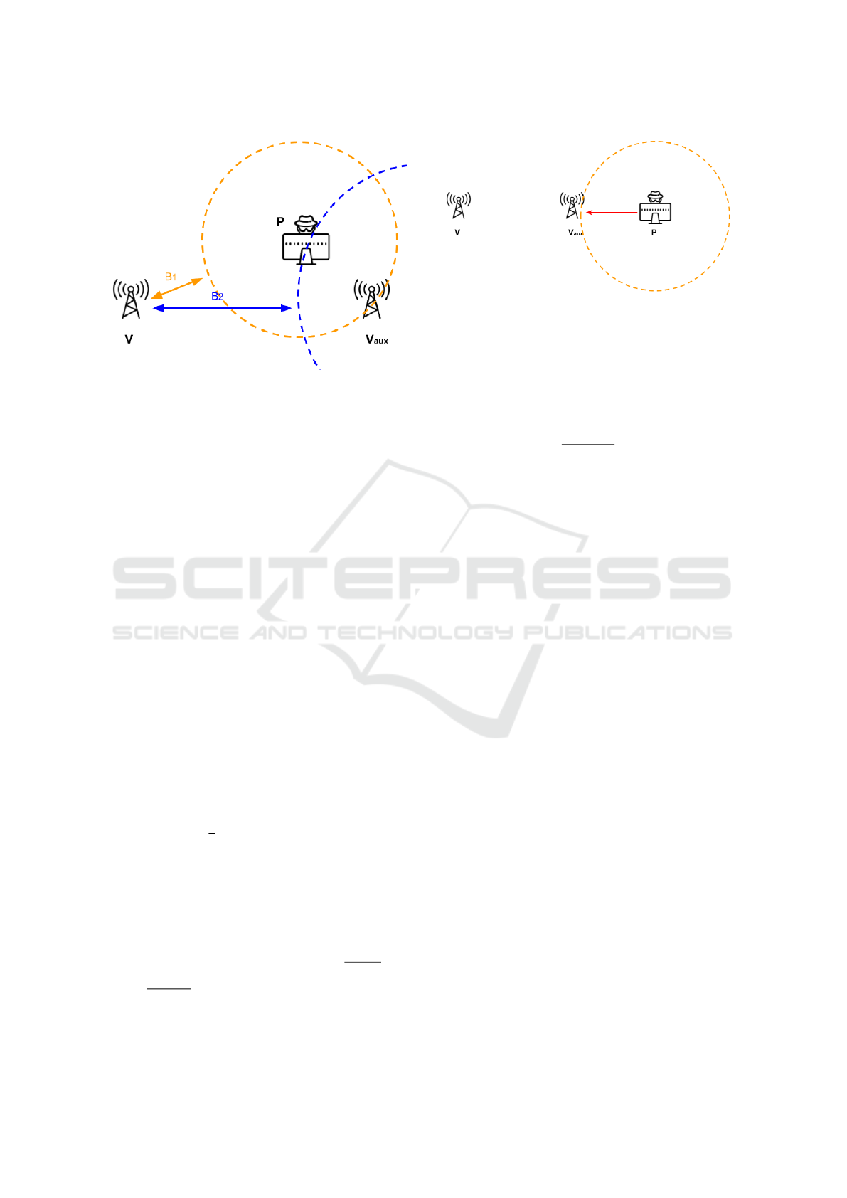
Figure 2: Sketch of P’s bound to the reduction fraud. Once
P chooses a value for k, it must take care not to exceed
the possible power transmitted by V
aux
. If it exceeds this
power, upon the first transmission from V
aux
, the attack is
identified.
to be away from V , by communicating a higher
P
0
rx
value.
As P uses a fixed value of k, it is not able to freely
choose its position in a 2D plane as it wishes, unless
it is DoA-capable. In this case it would be able to
select different delays/power increments for each
verifier and thus, freely control its position. Still,
assuming that P is not DoA-capable, it can always
choose its enlarged distance from both verifiers
with the constraint that its apparent 2D position is
constrained to a 1-D curve, created by intersecting
the two circles centered at the verifiers positions with
radiuses equal to the respective apparent distance
to P. Please, notice that every different k chosen
by P will lead to a different point in the 2-D plane,
but the distances from these points to each of the
verifiers have a constant ratio (in the mathematical
sense), given by r
0
= d
2
/d
1
, where d
1
and d
2
are the
distances from the prover to the closest and furthest
verifier, respectively. For simplification, we deal
here with gains in distance denoted by r, instead of
gains in power (k). In fact, when P multiplies its
P
rx
by a factor k, it changes its apparent distance
by a factor r =
γ
√
k, which depends on the path loss
exponent (Equation 3), but does not affect r
0
. If
r falls below a limit r
min
, then the circles do not
intersect. This constitutes a lower bound for r.
Additionally, since |d
1
−d
2
| grows with an increasing
r, after some point, given by r
max
, the circles will
not intersect anymore. This constitutes an upper
bound on r. It can be verified that r
min
=
d
v
1,2
(d
1
+d
2
)
and
r
max
=
d
v
1,2
d
1
·(r
0
−1)
, for r
0
> 1, where d
v
1,2
is the distance
between the verifiers. If r
0
= 1, then P is equidistant
Figure 3: Verifiers and prover aligned. The DoA-capable
prover cannot identify the verifiers. Reduction attacks are
bounded by the distance to V
aux
.
from both verifiers and lies on the line orthogonal to
the segment connecting the two verifiers, dividing
it in the middle. It can be also verified that the 1-D
curve on which P can virtually move is a circle
with radius R = d
1
·
(r
min
+r
max
)
2
centered at the point
(R − d
1
· r
min
,0), considering that v
1
(the closest
verifier) lies on the origin of the Cartesian system,
and that the line connecting the two verifiers defines
the x-axis of the system. The center of the circle
which defines the possible locations of P lies also on
the x-axis. The lower bound obtained here is assessed
in Section 5, while the upper bound is left as future
work.
4.3 Protecting against a DoA-capable
Prover
If P is DoA-capable, adding the second verifier to
the system, in principle, seems useless. The ran-
domized transmission sequence can be correctly in-
ferred by P upon verifying the angle under which the
signals arrived. Thus, P can freely insert different
power gains/attenuations to each incoming signal and
choose its position freely on the 2-D plane. This is
true, as long as the angles of the incoming signals
are not the same. If the angles are the same, i.e, V ,
V
aux
and P are aligned and positioned in this order, P
cannot tell which verifier transmitted the signal, and
randomization may still be effective. This scenario is
illustrated in Figure 3.
5 VALIDATION
In this section we combine the approaches proposed
in Section 4 using two verifiers with the physical path
loss measurements obtained with UWB from (Rubio
et al., 2013). In a simulated environment, we aim to
assess the impact of RSS imperfections on the correct
On the Potential of Distance Bounding based on UWB Received Signal Strength
11
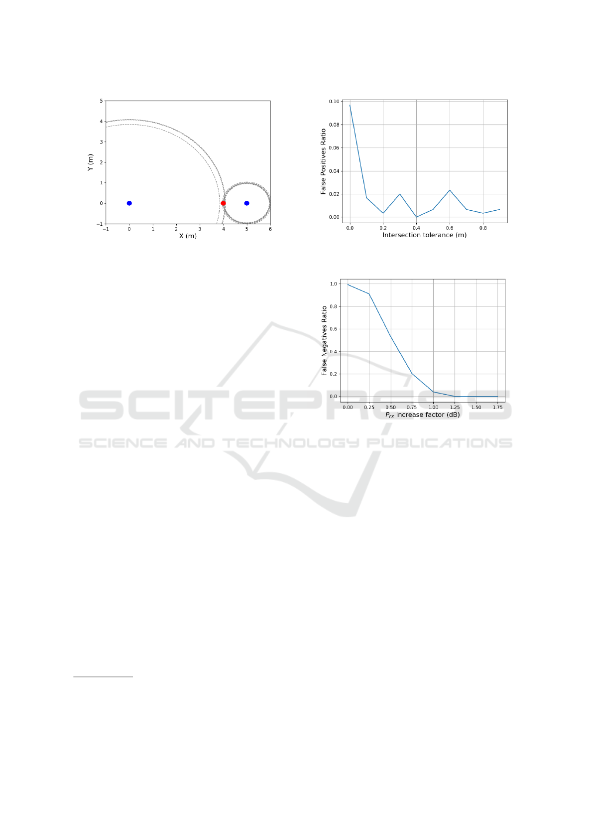
Figure 4: Simulated Environment. Filled circles in blue
and red represent the verifiers and the prover, respectively.
Dashed circles in gray represent the distances estimated by
each of the verifiers.
detection of the frauds, both enlargement and reduc-
tion, for different magnitudes of attacks. Prover and
verifiers are positioned at fixed locations, and each
verifier transmits a signal to the prover according to
a list randomly generated at the beginning of each
simulation round. Next, the prover measures/picks
one random value out of a Gaussian distribution in-
stantiated from (Rubio et al., 2013) according to its
real distance from the prover. The prover changes the
measurement by adding a constant power ∆
P
(in dB)
3
to P
rx
and communicates the values to V . If ∆
P
= 0
then the prover is honest. P is not DoA-capable and
V calculates the distance to P using Equation 3. An
attack is detected in case:
1. the standard deviation of estimations of a sin-
gle verifier for different transmit powers is above
0.3 m
4
;
2. there is no intersection of the circles around the
two different verifiers (please, refer to Figure 4);
3. P
0
rx
is less than −100 dBm.
Figure 4 illustrates the simulated environment.
5.1 False Positives Rate without Attack
In a first experiment, we aim to find a suitable toler-
ance so that the false positive rate, i.e., the number of
times that V detects an attack while no attack has been
performed, is sufficiently low. The number of trans-
missions is set to 8 in total for both verifiers and for
each tolerance value, varied from 0 cm to 1 m in steps
of 10 cm, we repeated the experiment 300 times. Fig-
ure 5 shows the results. It can be seen that when the
3
We switched from k to ∆
P
as we are dealing now with
power units in dB.
4
This value was obtained via simulations. Above this
threshold, the false positives rate is limited to 3 %.
Figure 5: False positives rate for ∆
P
= 0. With a 10 cm
tolerance the rate falls below 3 %.
Figure 6: False negatives rate for ∆
P
≥ 0. Attacks are al-
ways detected above a power increase of 1.25 dB.
tolerance is higher than 10 cm the false positives rate
falls below 3 %. We consider this rate acceptable, and
assume this tolerance for the next experiment.
We tried fine tuning this rate by increasing the
number of transmissions for each verifier. However, it
gets more likely to violate the first condition by doing
so, i.e., the standard deviation for the measurement of
each individual verifier increases. One possible so-
lution is to increase the standard deviation limit (set
to 0.3 m). This approach results in increasing the false
negatives rate, examined next. Therefore, we stick to
the default value for number of transmitted messages.
5.2 False Negatives Rate under DRF
In a second experiment, we count the occurrences of
false negatives, i.e., the number of times that V did not
detect an attack, but it was performed, as we vary the
magnitude (measured in dB) of the attack. In this ex-
periment, P performs the DRF to the leftmost verifier
(Figure 4). We show the results in Figure 6.
We can see that above an increase of 1.25 dB the
attacks are always detected. With this power increase,
PECCS 2020 - 10th International Conference on Pervasive and Parallel Computing, Communication and Sensors
12

Figure 7: False negatives rate for ∆
P
≤ 0. Attacks are de-
tected with a high probability above a power decrease of
23 dB.
P manages to come nearer, on average, 1.4 m to V .
Please, notice that we are not treating the attack as
a binary variable, but as a continuous one. As a re-
sult, with a small increase in power, the false negative
rate is very high. In particular, when it is 0 dB no
attack took place, and obviously, it should not be de-
tected. As a reference, in an ideal scenario without
ranging error, the maximum approximation achieved
would be 0 m for this setup.
5.3 False Negatives Rate under DEF
Next, we examine the (straightforward) approach to
bound enlargement attacks, which consists in check-
ing if the received power is below the sensitivity
threshold of a honest prover. In order to do this, we
exchange the original position of the verifiers, letting
V be the rightmost blue node in Figure 4. P’s goal is
to claim a further position from V by communicating
a lower received power, but it is theoretically bounded
by its distance to V
aux
, which is larger. The results are
shown in Figure 7.
In the absence of measurement error, an enlarge-
ment of ≈38 dB would be necessary to fall below the
sensitivity threshold of the transceiver. It was then
verified that the cause of the detected false negatives
was actually the variance of distances estimated by
the same verifier, often greater than 0.3 m. It hap-
pens because the absolute variance of the estimated
distances scales with the distance from the verifier,
which is enlarged by the prover. Therefore, another
mechanism to bound enlargement attacks is proposed,
namely, tuning the respective threshold to the maxi-
mum allowed distance value.
6 CONCLUSIONS AND FUTURE
WORK
In this paper, we discuss the potential to use signal
strength measurements as a building block for dis-
tance bounding protocols. It has been shown that, dif-
ferently from what has been assumed by the existing
literature, secure distance bounding protocols can be
implemented using the principle of power decay over
distance with UWB, which is less sensitive to multi-
path. By using realistic error models, we showed that
the proposed approaches manage to bound distance
frauds. Nonetheless, comparing the presented bounds
with the ones achieved using ToF measurements, it is
clear that ToF is usually superior. Additionally, un-
der the assumption that P affords a better process-
ing power (faster turn-around time) than V expects,
one can easily adapt the bound obtained in this paper
using two verifiers to the ToF setup, eliminating the
possible advantage of combining the two approaches
(ToF and RSS). A possible application for the UWB
RSS-based approach is to provide UWB pulse-based
transceivers not supporting accurate ranging, which
is an optional feature by the standard (802.15.4-2011,
2015), with a method for coarse distance estimation.
With this approach, vendors providing low-cost low-
power chips targeting wireless communication could
still provide some level of security against distance
frauds without increasing costs and complexity. To
the best of our knowledge, all vendors currently pro-
viding pulse-based UWB chips implement accurate
timestamping.
Future work includes:
• estimating distance using COTS pulse-based
UWB transceivers;
• investigate the effectiveness of RSS-based dis-
tance bounding to the other classes of distance-
related attacks;
• testing the proposed approaches on real setups
in order to verify if the proposed bounds are
achieved with COTS transceivers;
• optimizing the parameters of the system.
ACKNOWLEDGEMENTS
This research has been funded by the Austrian
Research Promotion Agency (FFG) and the Aus-
trian Federal Ministry for Transport, Innovation an
Technology (BMVIT), within the ”ICT of the Fu-
ture” project IoT4CPS (Trustworthy IoT for Cyber-
Physical Systems) (FFG, #863129) and COMET Cen-
ter Pro
2
Future (FFG, #854184) and has been partially
On the Potential of Distance Bounding based on UWB Received Signal Strength
13

supported by the TU Graz LEAD project Dependable
Internet of Things.
REFERENCES
802.15.4-2011 (2015). Ieee standard for low-rate wireless
networks. Standard, The Institute of Electrical and
Electronics Engineers, Inc., New York, USA.
Avoine, G., Bing
¨
ol, M. A., Boureanu, I.,
ˇ
capkun, S.,
Hancke, G., Kardas¸, S., Kim, C. H., Lauradoux,
C., Martin, B., Munilla, J., Peinado, A., Rasmussen,
K. B., Singel
´
ee, D., Tchamkerten, A., Trujillo-Rasua,
R., and Vaudenay, S. (2018). Security of distance-
bounding: A survey. 51(5).
Brands, S. and Chaum, D. (1993). Distance-bounding pro-
tocols. In Workshop on the Theory and Applica-
tion of of Cryptographic Techniques, pages 344–359.
Springer.
Capkun, S. and Hubaux, J. . (2005). Secure positioning of
wireless devices with application to sensor networks.
In Proceedings IEEE 24th Annual Joint Conference of
the IEEE Computer and Communications Societies.,
volume 3, pages 1917–1928 vol. 3.
Rubio, L., Reig, J., Fern
´
andez, H., and Rodrigo-Pe
˜
narrocha,
V. M. (2013). Experimental uwb propagation chan-
nel path loss and time-dispersion characterization in a
laboratory environment. International Journal of An-
tennas and Propagation, 2013:350167.
Singh, M., Leu, P., Abdou, A., and Capkun, S. (2019).
Uwb-ed: Distance enlargement attack detection in
ultra-wideband. In 28th USENIX Security Symposium
(USENIX Security 19), pages 73–88, Santa Clara, CA.
USENIX Association.
Zafari, F., Gkelias, A., and Leung, K. K. (2017). A survey of
indoor localization systems and technologies. CoRR,
abs/1709.01015.
Zheng, X., Safavi-Naini, R., and Ahmadi, H. (2014). Dis-
tance lower bounding. In International Conference on
Information and Communications Security, pages 89–
104. Springer.
PECCS 2020 - 10th International Conference on Pervasive and Parallel Computing, Communication and Sensors
14
