
Fuzzy Logic-based Adaptive Cruise Control for Autonomous Model Car
Khaled Alomari
a
, Ricardo Carrillo Mendoza, Stephan Sundermann, Daniel Goehring
and Ra
´
ul Rojas
Dahlem Center for Machine Learning and Robotics - Freie Universit
¨
at Berlin, Arnimallee 7, 14195 Berlin, Germany
Keywords:
Advanced Driver Assistance Systems, Adaptive Cruise Control, Fuzzy Logic.
Abstract:
One of the most critical challenges for the driver during highway driving is to adjust the vehicle speed con-
tinuously to maintain safe distance in respect to the heading vehicles or highway traffic. Neglecting a safe
distance can cause deadly collisions, especially at high velocities. Thus, car speed must adapt smoothly and
efficiently in relation to the velocity of the vehicle in front and the headway distance. Adaptive Cruise Control
(ACC) is an Advanced Driver Assistant System that is used to control both velocity and distance at the same
time. The system needs either a PID controller per state or a MIMO system. In this paper, we propose an ACC
using a Fuzzy Logic approach for an autonomous model car called “AutoMiny.” AutoMiny was developed at
the Dahlem Center for Machine Learning and Robotics at Freie Universit
¨
at Berlin. It navigates by correcting
its orientation error given by a global localization system and a pre-built grid map. The proposed controller
can handle two states with differently designed profiles, and we will compare the performance of our approach
with that of a PID controller.
1 INTRODUCTION
Advanced Driver Assistant Systems (ADAS) in vehi-
cles have had significant improvement over the last
decade. This is due to increased efforts from sev-
eral automotive manufacturers and the testing of self-
driving cars on public roads around the globe in re-
cent years, which induced even more significant in-
vestments by many industry members. Cars equipped
with ADAS with several automation features, such as
automatic parking systems, automotive night visions,
and automotive navigation systems have already be-
gun to appear in the market from various manufactur-
ers. These systems are meant not only to assist the
driver in driving efficiently but also to prevent col-
lision or accident probability (Naranjo et al., 2003).
Furthermore, self-driving vehicles have become no-
table for their potential to provide individual mobility
assistance (Chan, 2017).
Adaptive Cruise Control (ACC) is a vital ADAS
that almost all automotive manufacturers are aiming
to deliver in their modern cars. Vehicles provided
with cruise control are considered level 1 autonomous
cars as defined in SAE J3016 standard (SAE-J3016,
2018). It controls both velocity and distance based
on information provided by onboard sensors such as
a
https://orcid.org/0000-0001-7248-0056
laser scanners, radars, or cameras. These sensors help
to distinguish if the vehicle is approaching a vehi-
cle ahead so that it can adjust its speed and the dis-
tance to the car ahead to prevent a collision; other-
wise, it drives at a preset speed. ACC has been intro-
duced to significantly improve driver preference and
decrease workload as an intelligent driver assistance
system. Such a system helps to prevent accidents and
depreciate the consequences of an impact should one
occur by sustaining a safe gap and speed in the de-
sired range of the driver (Sang-Jin Ko and Ju-Jang
Lee, 2007) (Mamat and Ghani, 2009). Furthermore, it
can improve driving comfort, decrease driving errors,
enhance safety, expand traffic limits, and reduce fuel
consumption (Lu and Aakre, 2018).
There are multiple methods to implement Adap-
tive Cruise Control. Mathematical control-based
techniques produce reliable results but with high com-
putational and design costs. Using fuzzy logic for
ACC has been in academia and industry for many
years (Sang-Jin Ko and Ju-Jang Lee, 2007) (Pana-
nurak et al., 2009). However, most publications fo-
cused on experiments in a simulation environment
(Basjaruddin et al., 951) (Singh et al., 2015). This pa-
per presents a large amount of interesting experimen-
tal results to compare the performance of our fuzzy
logic controller with that of a PID controller.
Alomari, K., Mendoza, R., Sundermann, S., Goehring, D. and Rojas, R.
Fuzzy Logic-based Adaptive Cruise Control for Autonomous Model Car.
DOI: 10.5220/0010175101210130
In Proceedings of the International Conference on Robotics, Computer Vision and Intelligent Systems (ROBOVIS 2020), pages 121-130
ISBN: 978-989-758-479-4
Copyright
c
2020 by SCITEPRESS – Science and Technology Publications, Lda. All rights reserved
121
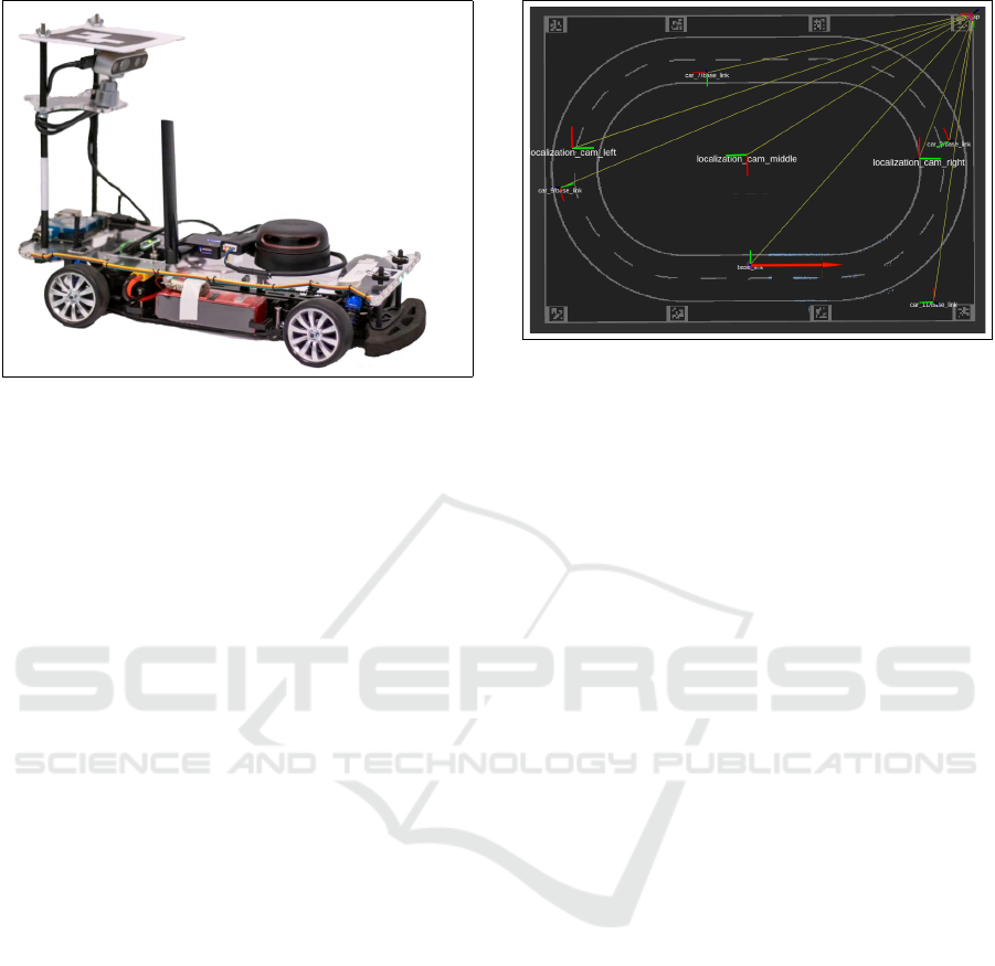
Figure 1: AutoMiny: a model car developed at Dahlem
Center for Machine Learning and Robotics at Freie Uni-
versit
¨
at Berlin.
2 HARDWARE
2.1 Model Car ”AutoMiny”
AutoMiny is a 4WD Ackermann steering model-
vehicle (scale 1:10), developed at the Dahlem Center
(Mendoza et al., 2019) and shown in Figure 1. It is
programmed to drive in fully autonomous mode. The
vehicle has the dimensions (L x W x H) 445 mm x 195
mm x 300 mm. The central computer is an Odroid-
XU4 running Ubuntu 18.04 and the Robotic Operat-
ing System (ROS) melodic on top (Stanford Artificial
Intelligence Laboratory et al., 2018). The model car
has been motorized with a brushless DC-servomotor
with a built-in encoder and a servo motor with analog
feedback for steering.
Sensors and electronics are fixed in one layer. The
sensors in the vehicle include a 360
◦
rotating laser
scanner which detects obstacles and walls around the
vehicle, and an IMU module provides measurements
from a combined 3-axis gyroscope and 3-axis ac-
celerometer. A Kinect-type stereoscopic system has
been mounted on top of the car’s body. It has an Intel
D435 RealSense camera and a aruco marker mounted
on top of it. The aruco marker encodes the car ID and
is used to obtain the global localization of the car. The
vehicle has 2 LED stripes for simulating the head- and
taillights, as well as turning and brake lights.
2.2 Lab Setup
A 600 * 430 [cm
2
] map was prepared to test and run
AutoMiny in the lab. The map had two lanes, the
outer one 14.78 [m] long, and the inner one 12.76 [m].
Figure 2: Lab road map used to test ACC on the model car.
A bounded indoor localization system was built to
help the car navigate on the map. The system con-
sisted of 3 cameras mounted on the ceiling and point-
ing towards the floor. Those three cameras provided
a full image of the map where the car could move.
Eight different aruco markers were fixed on the map,
as shown in Figure 2. Each camera on the ceiling
could see four aruco markers at the same time to find
their pose, and could detect the car if it was located
in its field of view, which was usually between those
four markers.
3 ADAPTIVE CRUISE CONTROL
Since the car is a nonlinear element, and its analyt-
ical description is complex, the employment of ar-
tificial intelligence approaches (such as fuzzy logic
control) is a way to reach human-like speed control.
It is an expert system based on if-then rules which
allow it to overcome some limitations of other lin-
ear control frameworks. Even though fuzzy logic
is somewhat controversial, it is a sturdy technique.
It allows control without comprehensive knowledge
of the controlled system state, and it represents in
a very productive way the rational argumentation
means (Naranjo et al., 2003).
3.1 Design ACC based on Fuzzy Logic
Approach
For this work, Mamdani fuzzy inference method was
used. Figure 3 shows a fuzzy logic control block dia-
gram. Relative distance and relative speed between
the cars are used as inputs for the controller, and
the output is the acceleration (Milanes et al., 2012).
The tests involved an adequately rich set of behaviors
(straight line motion, on curve motion). During the
ROBOVIS 2020 - International Conference on Robotics, Computer Vision and Intelligent Systems
122
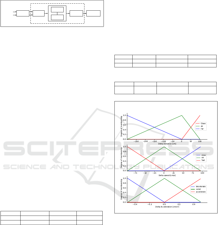
Preprocessing
PostprocessingDefuzzification
Inference
engine
Rule Base
Inference
engine
Rule Base
Fuzzy Controller
Distance
Velocity
Fuzzification
Figure 3: Blocks of fuzzy controller (Jantzen, 1998).
tests, the variety of values for each input and output
variable had to span the whole intervals of exposition
necessary for the predicted performance of the con-
troller (Driankov and Saffiotti, 2001). However, since
the experiment was in a lab, these intervals were set
to limit the car’s speed and the desired distance range.
Distance and velocity also laid within these known
intervals. Thus, input-output data should cover these
intervals.
Fuzzy logic gives the designer more flexibility to
define the error based on his needs. Here we choose
the controller inputs to be the difference between de-
sired value and actual value
e
d
= d
des
− d
act
(1)
e
v
= v
des
− v
act
(2)
Table 1 shows the desired and the actual intervals
for each input variable of the controller. The actual
intervals are chosen based on different aspects includ-
ing safety distance and sensors’ accuracy. The desired
intervals are chosen based on the tolerance of the de-
sign. The final intervals (the controller inputs) are cal-
culated as follows:
∆d
min
= 200 − 500 = −300 [cm]
∆d
max
= 300 − 200 = +100 [cm]
∆v
min
= 10 − 105 = −95 [cm/s]
∆v
max
= 100 − 5 = +95 [cm/s]
Table 1: Input - Output variables intervals.
Variable Desired Range Actual Range Final Range
∆d [cm] [+200,+300] [+200,+500] [−300,+100]
∆v [cm/s] [+10,+100] [+5,+105] [−95,+95]
After defining the Input-Output range values for
the controller, we should assign linguistic terms for
each input and output interval, and then choose a
membership function. These linguistic terms are
known as fuzzy set.
Recognizing the necessity of a quick response
from the ACC, a triangular membership function
was chosen based on the results from (Ahmad and
Basiran, 2015). It proved that using triangular or
trapezoid membership functions utilized fewer com-
puter resources compared to the Gaussian approach,
although while Gaussian membership consumes more
computational time to process the information, the
outcome is more precise. However, for such a sys-
tem, the rejoinder is weighted more than the accuracy
in the output value as long as this system is designed
for AutoMiny in the lab environment.
Tables 2 and 3 show the list and arrangement of
the ACC input and output quantities with its fuzzy
set and Figure 4 visualizes fuzzy set partitioning and
membership functions of input and output intervals.
Table 2: List of input variables for the fuzzy controller.
Input Value Range Linguistic variable Linguistic terms
∆d [cm] [−300,+100] Distance Far, Ok, Close
∆v [cm/s] [−95,+95] Speed Fast, Ok, Slow
Table 3: List of output variables for the fuzzy controller.
Output Value Range Linguistic variable Linguistic terms
∆a [cm/s
2
] [−0.5,+0.5] Acceleration
Decelerate, Ok,
Accelerate
Figure 4: Definition of membership functions and Fuzzy
sets.
3.1.1 Preprocessing
As mentioned before, the two inputs for the controller
were the change of speed and change of distance.
Based on what is described in section 2.2, the po-
sition and speed data for the ego- and the target-car
were received from the simulated GPS in the lab. Still,
this data needs to be averaged before passing it to the
fuzzy controller to obtain longer-term tendencies as
the data is most often crisp. This happens in the pre-
processing step (Jantzen, 1998).
The GPS provides the car’s position on the field
at 30 Hz frequency. However, we calculate the dis-
Fuzzy Logic-based Adaptive Cruise Control for Autonomous Model Car
123
X
Y
X
Y
Nearest Point
Euclidean Distance
Target_car
Ego_car
Nearest Point
Grid map
2 2 2
( , )P x y
1 1 1
( , )P x y
Actual
Distance
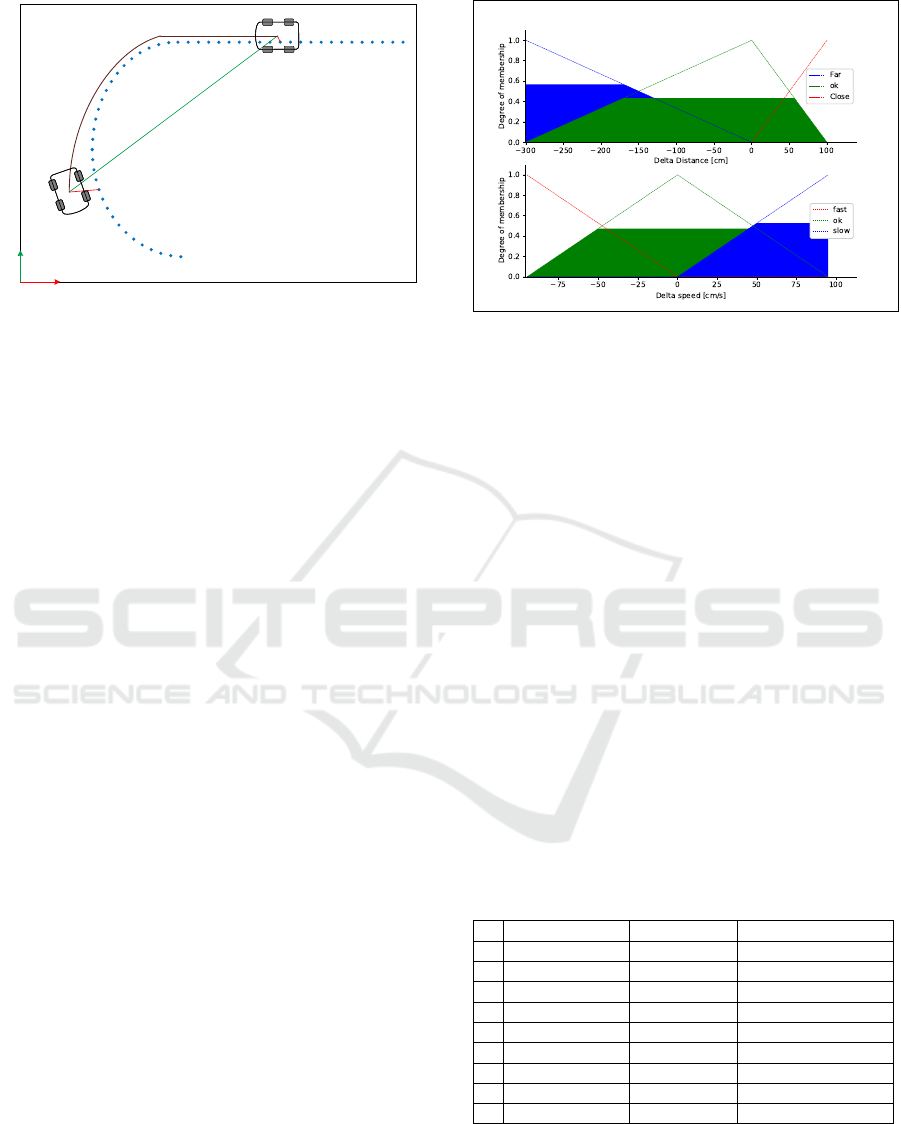
Figure 5: Relative distance calculation.
tance between the cars along the path as presented in
in Figure 5. On the other hand, calculating the rela-
tive speed is faster. We receive both cars’ linear speed
data from our local GPS server. When the inputs data
is proper and ready, the preprocessor passes it on to
the controller.
3.1.2 Fuzzification
A fuzzy controller deals only with linguistic rather
than crisp variables. Hence, a step called fuzzification
is needed for each received input data. Fuzzification
means converting the obtained input data to a degree
of membership for each fuzzy set in the membership
functions so that we can use it in the fuzzy controller
rules. As an example, an arbitrary error in distance
and speed of -170 [cm] and 50 [cm/s] respectively are
taken as input values for the ACC fuzzy controller.
Figure 6 shows the fuzzification results for them. The
distance error input value has approximately 0.56 de-
grees of membership for “far” fuzzy set and 0.44 for
“ok” fuzzy set, while it does not have any degrees of
membership for the “close” fuzzy set. Meanwhile, the
velocity error input value has approximately 0.48 de-
grees of membership for “ok” fuzzy set and 0.52 for
“slow” fuzzy set, while it does not have any degrees
of membership for the “fast” fuzzy set.
Delta Distance = Far: µ
deltaDistanceFar
(−170) = 0.56
Delta Distance = OK: µ
deltaDistanceOK
(−170) = 0.44
Delta Distance = Close: µ
deltaDistanceSlow
(−170) = 0.0
Delta Speed = Fast: µ
deltaSpeedFast
(50) = 0.0
Delta Speed = OK: µ
deltaSpeedOK
(50) = 0.48
Delta Speed = Slow: µ
deltaSpeedSlow
(50) = 0.52
Figure 6: Fuzzification for input values.
3.1.3 Rule Base
Fuzzy control rules have an if-then format. They are
built based on designer expertise and demands. An
example of one rule is:
if Delta Distance is Close and Delta Velocity is Slow
then Decelerate
The relational format essentially assumes that the
connective between the inputs is always a logical
connective. It should be emphasized, though, that
it has to be the same operation for all rules and
not a mixture of connectives (Michels et al., 2006).
Logical and and logical or are the most prominent,
and they are always defined in pairs (Jantzen, 1998):
a and b = min(a,b)
a or b = max(a,b)
Table 4 exposes the fuzzy rules base for our ACC.
The first two columns are inputs and the right most is
an output. Each row represents a rule. Safety, power
consumption, and ride comfort were the aspects taken
into account when defining the rules.
Table 4: Fuzzy Rule Base.
Delta Distance Delta Speed Delta Acceleration
1 Close Slow Decelerate
2 Close OK Decelerate
3 Close Fast Decelerate
4 OK Slow Constant
5 OK OK Constant
6 OK Fast Decelerate
7 Far Slow Accelerate
8 Far OK Constant
9 Far Fast Decelerate
3.1.4 Inference Engine
The inference engine looks up the membership grades
in the condition for each rule. Let us continue with the
ROBOVIS 2020 - International Conference on Robotics, Computer Vision and Intelligent Systems
124
example we mentioned in section 3.1.2 by applying
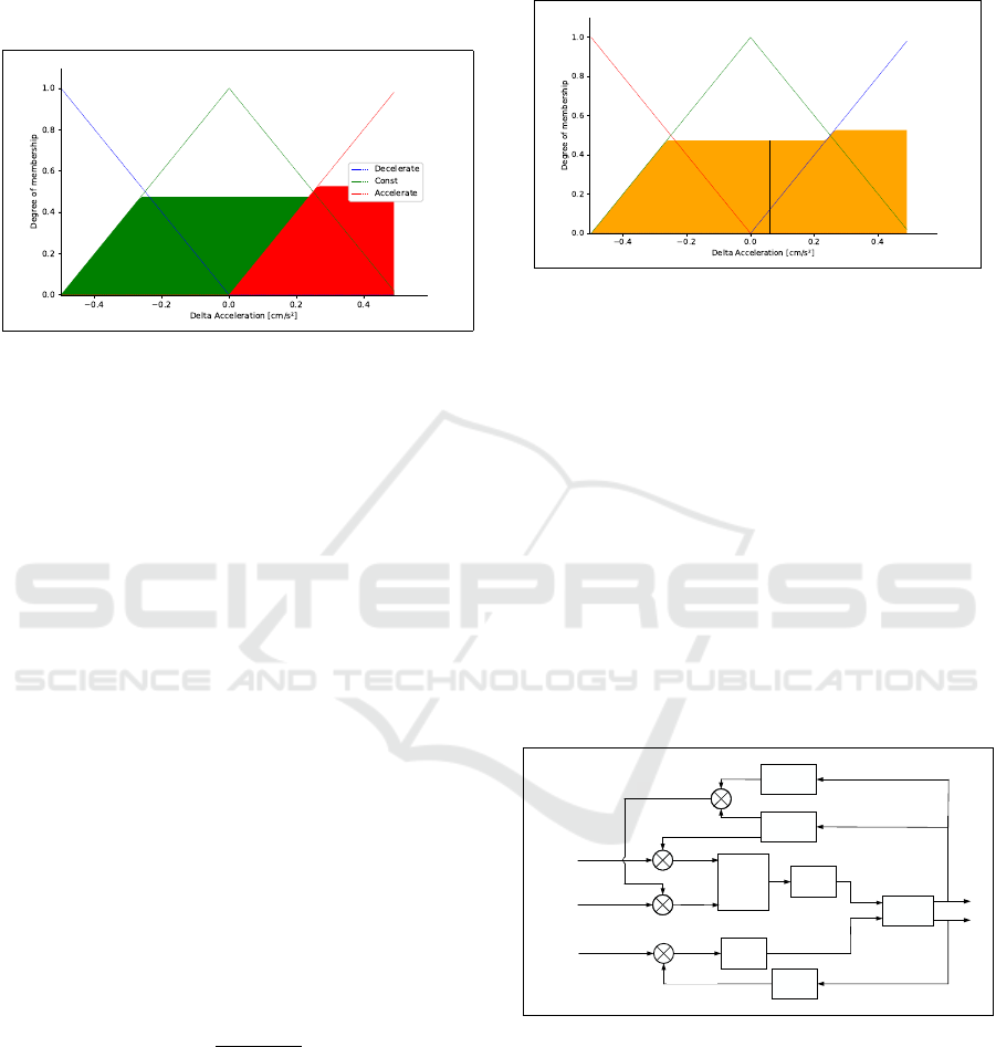
the rule base mentioned in Table 4. Figure 7 manifests
the output membership activity of the ACC fuzzy con-
troller i.e. the fuzzification of the output values results
from applying the rules.
Figure 7: Output membership activity.
Rule 1 min(0.0;0.52) = 0.0
Rule 2 min(0.0;0.48) = 0.0
Rule 3 min(0.0;0.0) = 0.0
Rule 4 min(0.44;0.52) = 0.44
Rule 5 min(0.44;0.48) = 0.44
Rule 6 min(0.44;0.0) = 0.0
Rule 7 min(0.56;0.52) = 0.52
Rule 8 min(0.56;0.48) = 0.48
Rule 9 min(0.56;0.0) = 0.0
H
Decelerate
= max(0.0;0.0; 0.0;0.0;0.0) = 0.0
H
Constant
= max(0.44; 0.44;0.48) = 0.48
H
Accelerate
= max(0.52) = 0.52
3.1.5 Defuzzification
The resulting fuzzy set needs to be transformed into
a number that can be sent for processing as a con-
trol signal; this is called defuzzification. There are
numerous techniques for defuzzification such as Cen-
ter of Gravity, Bisector of Area, and Mean of Max-
ima. However, we proceeded with the first method
Abscissa, under the Center of Gravity. The output
value X can be calculated using the formula:
X =
∑
i
µ(x
i
) x
i
∑
i
µ(x
i
)
(3)
where:
µ(x
i
) : the membership value of the membership
function
x
i
: a running point in the discrete universe
Figure 8 exposes the final aggregated fuzzy set
for the example from section 3.1.2 and the final out-
put value (delta acceleration), which then will pro-
cess as a control signal. The controller output is:
∆a = 0.06 [cm/s
2
]
Figure 8: Aggregated membership and result (line).
3.1.6 Postprocessing
Output scaling is also relevant. In most cases, the out-
put value needs to be scaled to physical units. In our
case, the controller output value is a change of accel-
eration. Since we are not able to send an acceleration
command to the speed motor, we will use a low-level
controller (based upon motor calibration and desired
response time) to convert the controller output into a
value that can be sent to the motor. The low-level
control equations are shown in section 3.2.
The block diagram for controlling AutoMiny ACC
using a Fuzzy logic approach and steering using a PID
controller can be seen in Figure 9. When applying the
ACC, the lead car speed is taken as the desired speed
while the desired distance is set manually.
Ego
speed
Ego
position
Lead
position
yaw
desired
car2car
ACC
Fuzzy Logic
PID
Steering
Low-level
Control
AutoMiny
Servo
Feedback
Δd
Δa
Localization
Δv
Velocity
−
−
−
−
−
−
Steering
−
−
−
−
−
−
Δyaw
d
desired
v
desired
d
actual
yaw
actual
Figure 9: AutoMiny control block diagram with Fuzzy
ACC.
3.2 Designing of Low-Level Control
Low-Level Control (LLC) is used to map the output of
the ACC from acceleration to a speed command that
can be fed to the motor. The equation of this control is
based on both motor calibration curve and the desired
response time. However, the same LLC is employed
Fuzzy Logic-based Adaptive Cruise Control for Autonomous Model Car
125
for both ACC fuzzy logic-based and PID based sys-
tems. The equation is set as follows:
∆a = a
des
− a
act
(4)
a
des
= a
act
+ ∆a (5)
v
des
t
=
v
act
t
+ ∆a (6)
v
des
= v
act
+ ∆a t (7)
Now, the actual speed is measured in [m/s] while
we send the desired speed to the motor in [rpm]. Thus,
based on motor calibration curve we choose a con-
stant K
1
as:
V
act
[rpm] =
v
act
[m/s]
K
1
(8)
we also define a second constant K
2
so that:
t = K
2
(9)
from all above, we get the final LLC equation as
follow:
V
des
=
v
act
K
1
+ ∆a K
2
+ K
3
(10)
where:
V
des
: speed command send to the motor in [rpm]
v
act
: ego car actual speed [m/s]
K
1
: constant based on motor calibration
K
2
: response time
K
3
: constant speed to prevent the car driving
backward in [rpm]
4 EVALUATION
In this section, we will compare our approach of
implementing ACC using the fuzzy logic on Au-
toMiny with a standard PID controller quantitatively
and qualitatively. The goal is to distinguish how sta-
ble the controller is. Since the ACC has two inputs
(delta distance and delta speed) and operates in ve-
locity control mode and distance control mode (Singh
et al., 2015), while a PID can control one input vari-
able only, we need to compare each mode with a dif-
ferent PID controller.
All experiments were performed inside the lab us-
ing two model cars, the leading one used as a dynamic
target, and the ego car following it with the proposed
controllers.
Ego
position
Lead
position
yaw
actual
d
desired
car2car
PID
Steering
Low-level
Control
AutoMiny
Servo
Feedback
Δd
Δa
Localization
Velocity
−
−
−
−
−
Steering
−
−
−
−
PID
Distance
Δyaw
yaw
desired
d
actual
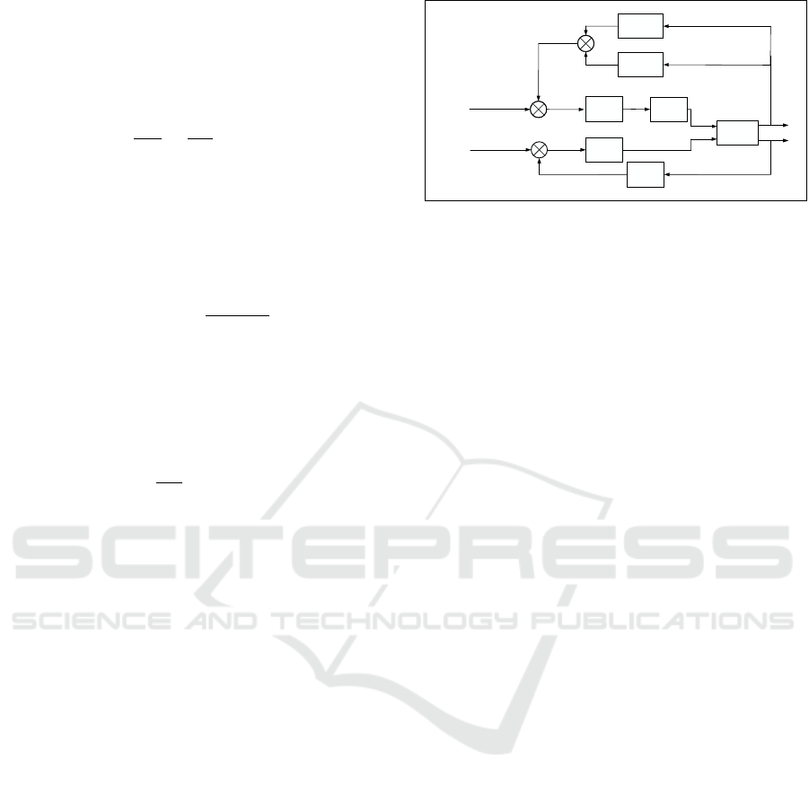
Figure 10: AutoMiny control block diagram with PID dis-
tance control.
4.1 Distance Control Mode
For this experiment, a standard PID distance control
is designed. Figure 10 shows the final block diagram
for AutoMiny control after implementing the distance
PID controller.
4.1.1 Catch-up Time
In this experiment, the catch-up time starting from ac-
tivating ACC until it reaches its steady-state was ob-
served for both controllers. The idea is to distinguish
which controller has a faster response time compared
to the other. The initial parameters were granted and
set as follows:
• Lead car initial speed = 0.55 [m/s]
• Ego car initial speed = 0.85 [m/s]
• Desired distance = 100 [cm]
• ACC activates automatically when ∆d ≤ 200 [cm]
Figure 11 shows in the first plot, the actual dis-
tance response for both controllers and the desired
distance, although the second plot shows the abso-
lute error in the distance for both controllers (the dis-
tance error is the controller’s input variable). From
it, we can observe that both controllers had roughly
the same response time; still, the PID controller os-
cillated during the regulation period, while the fuzzy
logic controller had a smooth transition which in turn
means greater travel comfort.
Since the output of the controllers is not on the
same scale, comparing them on their scale is not prac-
tical. Thus, we normalized the output data (acceler-
ation) for both controllers. The normalized acceler-
ation for both controllers can be seen in Figure 12.
The fuzzy logic controller had a smoother response
compared to the distance PID. As a result of this ex-
periment, we can state that the fuzzy logic controller
has a better performance adjusting the distance to the
desired value.
ROBOVIS 2020 - International Conference on Robotics, Computer Vision and Intelligent Systems
126
0 10 20 30 40 50 60
time [s]
50
100
150
200
Actual distance [cm]
Desired distance
Fuzzy Logic
PID
0 10 20 30 40 50 60
time [s]
0
20
40
60
80
100
Absolute distance Error [cm]
Fuzzy Logic
PID
Figure 11: Actual distance and the absolute distance error
during response time testing; both controllers are activated
automatically when ∆d ≤ 200 [cm].
0 10 20 30 40 50 60
time [s]
-4
-2
0
2
4
Normalized accleration [m/s
2
]
Fuzzy Logic
PID
Figure 12: Actual output for both controllers during re-
sponse time testing.
0 10 20 30 40 50 60
time [s]
0.2
0.4
0.6
0.8
Actual speed [m/s]
Front Car Speed
Fuzzy Logic
PID
0 10 20 30 40 50 60
time [s]
0
0.1
0.2
0.3
Absolute speed Error [m/s]
Fuzzy Logic
PID
Figure 13: Actual speed and the absolute speed error during
response time testing.
The output of the distance PID controller is ac-
celeration, therefore controlling the distance involves
internally adjusting the speed of the car based on the
PID output. Moreover, during the experiment, the de-
sired distance was constant. Thus, we can compare
the car velocity changes with both controllers. Fig-
ure 13 shows the actual velocity and absolute velocity
error.
Table 5: Root Mean Squared Error and Standard Deviation
for distance, speed, and acceleration for both controllers
during the response time test.
e
dis
e
vel
e
acc
RMS SD RMS SD RMS SD
FL 22.6906 22.1361 0.0699 0.0655 0.0061 0.0049
PID 23.4570 22.9583 0.1097 0.1078 0.0234 0.0229
In order to summarize the plots information in
Figures 11, 12, and 13, the Root Mean Squared Error
and the Standard Deviation for distance, speed, and
acceleration of each controller are shown in Table 5.
We can note that both controllers have approximately
the same values. Nevertheless, from plots, we can dis-
tinguish that the fuzzy logic controller is more stable
while transitioning.
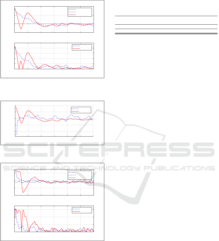
4.1.2 Change of Desired Distance
In this experiment, the initial parameters were granted
and set as follows:
• Lead car initial speed = 0.75 [m/s]
• Ego car initial speed = 0.85 [m/s]
• Initial desired distance = 100 [cm]
• ACC activates automatically when ∆d ≤ 200 [cm]
During the experiments, the desired distance was
changed from 100 [cm] to 160 [cm] and back to 100
[cm] in steps of 30 [s] while the leading vehicle stayed
driving at its initial constant speed. The idea was to
witness the response of both distance PID controller
and the fuzzy logic controller for desired distance
changes and establish which one has a better rejoinder
in the same implementation condition.
Figure 14 shows in the first plot the actual distance
behavior for both controllers while changing the de-
sired distance. The second plot shows the absolute
error in the distance for both controllers. We can see
that both controllers reacted to the changes in the de-
sired distance; still, the fuzzy controller had less error
than the PID one, which means it was more dynamic.
Figure 15 shows both controllers normalized out-
put. We can figure that the fuzzy logic controller has
a more stable response to the changes in the desired
distance compared to the distance PID controller.
In Figure 16, we can see the actual (measured) ve-
locity and the absolute velocity error for both con-
trollers. We can observe both controllers’ suitabil-
ity to control the ego car speed in a proper response.
Nevertheless, the primary controlled variable in this
experiment was the distance, and the fuzzy logic con-
troller showed more stable behavior.
Again, we summarize the plots information of
Figures 14, 15, and 16 in Table 6 where the Root
Fuzzy Logic-based Adaptive Cruise Control for Autonomous Model Car
127
0 10 20 30 40 50 60 70 80 90
time [s]
100
150
200
Actual distance [cm]
Desired distance
Fuzzy Logic
PID
0 10 20 30 40 50 60 70 80 90
time [s]
0
20
40
60
80
100
Absolute distance Error [cm]
Fuzzy Logic
PID
Figure 14: Actual distance and the absolute distance error
as a consequence of changing the desired distance; the de-
sired distance was changed from 100 [cm] to 160 [cm] and
back to 100 [cm] in steps of 30 [s] while the leading vehicle
stayed driving at its initial constant speed.
0 10 20 30 40 50 60 70 80 90
time [s]
-3
-2
-1
0
1
2
3
Normalized accleration [m/s
2
]
Fuzzy Logic
PID
Figure 15: Actual output for both controllers as a con-
sequence of changing the desired distance. The desired
distance was modified at 30 [s] and 60 [s] demanding a
sharp decelerate or accelerate. The fuzzy logic controller
responded more gently than the PID one.
0 10 20 30 40 50 60 70 80 90
time [s]
0.5
0.6
0.7
0.8
0.9
Actual speed [m/s]
Front Car Speed
Fuzzy Logic
PID
0 10 20 30 40 50 60 70 80 90
time [s]
0
0.05
0.1
0.15
0.2
0.25
Absolute speed Error [m/s]
Fuzzy Logic
PID
Figure 16: Actual speed and the absolute speed error as a
consequence of changing the desired distance. The desired
distance was modified at 30 [s] and 60 [s] demanding sharp
changes in speed.
Mean Squared Error and the Standard Deviation for
distance, speed, and acceleration of each controller
Table 6: Root Mean Squared Error and Standard Deviation
for distance, speed, and acceleration for both controllers as
a consequence of changing the desired distance.
e
dis
e
vel
e
acc
RMS SD RMS SD RMS SD
FL 22.2484 21.9750 0.0850 0.0842 0.0066 0.0051
PID 39.0971 22.6541 0.0695 0.0674 0.0390 0.0226
yaw
actual
PID
Steering
Low-level
Control
AutoMiny
Servo
Feedback
Δv
Δa
Localization
Velocity
−
−
Steering
−
−
−
−
PID
Speed
Δyaw
v
desired
yaw
desired
Ego
speed
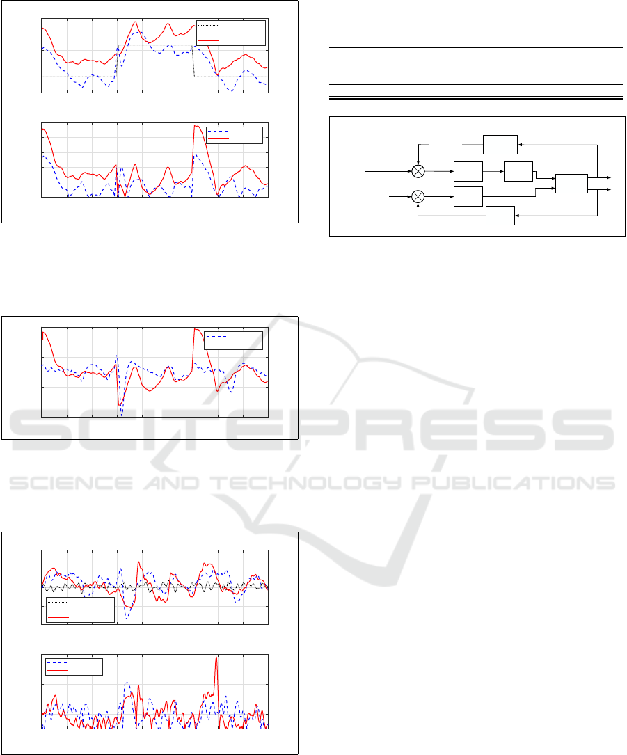
Figure 17: AutoMiny control block diagram with PID speed
control.
is measured. Here, we can note that both controllers
could control the distance and keep the error small.
Nevertheless, Figure 15 proved that the fuzzy logic
controller had a more stable response to the changes
in the desired controlled variable. As a conclusion
of this analysis, we found that the fuzzy logic con-
troller had a better performance adjusting the desired
distance to a dynamic obstacle moving with a constant
speed.
4.2 Velocity Control Mode
For this experiment, a standard speed PID controller
was designed for the ego car in order to compare the
velocity control mode between the fuzzy logic con-
troller and the speed PID controller. Figure 17 shows
the final block diagram for AutoMiny control after
implementing the speed PID controller.
The initial parameters in this experiment were set
as follows:
• Lead car initial speed = 0.5 [m/s]
• Ego car initial speed = 0.85 [m/s]
• Initial desired distance = 120 [cm]
• ACC activates automatically when ∆d ≤ 200 [cm]
During the experiment, the dynamic target veloc-
ity was changed from 0.5 [m/s] to 0.75 [m/s] and
back to 0.5 [m/s] in steps of 60 [s] while the desired
distance (the distance to the front car) was constant.
The idea is to test the response of both the speed PID
controller and the fuzzy logic controller and ascertain
which one has a more solid response in the same im-
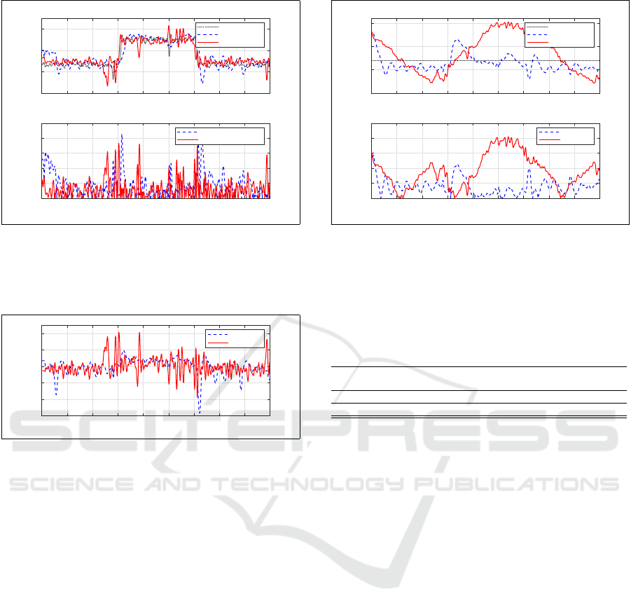
plementation condition. Figure 18 shows in the first
plot the actual velocity behavior for both controllers
and while changing the target speed. The second plot
ROBOVIS 2020 - International Conference on Robotics, Computer Vision and Intelligent Systems
128
0 20 40 60 80 100 120 140 160 180
time [s]
0.2
0.4
0.6
0.8
Actual speed [m/s]
Front Car Speed
Fuzzy Logic
PID
0 20 40 60 80 100 120 140 160 180
time [s]
0
0.05
0.1
0.15
0.2
0.25
Absolute speed Error [m/s]
Fuzzy Logic Speed Error
PID Speed Error
Figure 18: Actual speed and the absolute speed error as a
consequence of changing the desired speed. The desired
velocity was changed from 0.5 [m/s] to 0.75 [m/s] and back
to 0.5 [m/s] in steps of 60 [s] while the desired distance
remain constant.
0 20 40 60 80 100 120 140 160 180
time [s]
-6
-4
-2
0
2
4
Normalized accleration [m/s
2
]
Fuzzy Logic
PID
Figure 19: Actual output for both controllers as a conse-
quence of changing the desired speed. The desired veloc-
ity was modified at 60 [s] and 120 [s] demanding a sharp
decelerate or accelerate. Both controllers responded signif-
icantly.
shows the absolute error in the velocity for both con-
trollers. It is notable that both controllers reacted in
almost the same way; however, the PID controller os-
cillated more than the fuzzy logic controller.
Figure 19 shows both controllers’ normalized out-
put (acceleration) versus time and demonstrated that
the PID controller output oscillated. This means that
such a system might not be suitable to be imple-
mented in a real car even though it does control the
speed significantly.
In Figure 20, we plot the actual distance and dis-
tance absolute error in both the speed PID controller
and the fuzzy logic one. The figure shows that while
the fuzzy logic controller approached the desired dis-
tance, it still could not adequately control it, while the
speed PID controller was completely unable to regu-
late the distance during speed control mode.
Finally, we summarize the information of Figures
18, 19, and 20, the Root Mean Squared Error and the
Standard Deviation for distance, speed, and accelera-
tion of each controller in Table 7. We can remark that
0 20 40 60 80 100 120 140 160 180
time [s]
50
100
150
200
Actual distance [cm]
Desired distance
Fuzzy Logic
PID
0 20 40 60 80 100 120 140 160 180
time [s]
0
20
40
60
80
100
Absolute distance Error [cm]
Fuzzy Logic
PID
Figure 20: Actual distance and the absolute distance error as
a consequence of changing the desired speed. The desired
velocity was modified at 60 [s] and 120 [s]. The fuzzy con-
troller could control the desired distance as a consequence
of changing the desired speed.
Table 7: Root Mean Squared Error and Standard Deviation
for distance, speed, and acceleration for both controllers as
a consequence of changing the desired speed.
e
dis
e
vel
e
acc
RMS SD RMS SD RMS SD
FL 18.8717 17.9386 0.0720 0.0711 0.0092 0.0069
PID 52.9020 39.5351 0.0561 0.0557 0.0101 0.0101
both controllers could control the velocity and main-
tain a small error during transitioning. However, we
recognize that the fuzzy controller responded to the
changes in desired controlled variable smoothly while
maintaining a small distance error.
5 CONCLUSIONS
This paper proposes a fuzzy logic-based Adaptive
Cruise Controller. Chapter 1 introduced the prob-
lem and defined the primary goals. Chapter 2, briefly
described the hardware used throughout this experi-
ments. In Chapter 3, we presented description of de-
veloping an Adaptive Cruise Controller using Fuzzy
Logic. Finally, in chapter 4, we evaluated the con-
troller against a distance PID and a velocity PID using
a second leading model car in a lab environment on a
race track.
Experiment results showed that the tracking ve-
hicle follows a leading vehicle gently by controlling
both speed and distance even when their desired val-
ues are changed during operation. This indicates the
possibility of constructing an independent desired be-
havior per state—in the appropriate environment and
condition— which can take into account other impor-
tant driveability factors such as the comfort of acceler-
Fuzzy Logic-based Adaptive Cruise Control for Autonomous Model Car
129

ation rate or optimal energy consumption. Challenges
with these controlling approaches rely on the fact that
fuzzy controllers have many adjustable variables that
must be calibrated by hand. Depending on the com-
plexity of the desired behavior, the number of calibra-
tion variables can be more than triple the parameters
on a conventional PID controller. Nevertheless, we
show that the trade-off between controller simplicity
and performance of the proposed fuzzy controller is
advantageous for ACC systems.
REFERENCES
Ahmad, H. and Basiran, S. N. A. (pp 9773 - 9778, Novem-
ber 2015). Fuzzy logic based vehicle speed control
performance considering different membership types.
ARPN Journal of Engineering and Applied Sciences,
Vol. 10, No. 21.
Basjaruddin, N. C., Kuspriyantoand, Saefudin, D., and Nu-
graha, I. K. (December 2014, pp 944 - 951). Develop-
ing adaptive cruise control based on fuzzy logic using
hardware simulation. International Journal of Electri-
cal and Computer Engineering (IJECE), Vol. 4, No. 6.
Chan, C.-Y. (2017). Advancements, prospects, and impacts
of automated driving systems. International Journal
of Transportation Science and Technology, 6(3):208 –
216. Safer Road Infrastructure and Operation Man-
agement.
Driankov, D. and Saffiotti, A. (2001). Fuzzy Logic Tech-
niques for Autonomous Vehicle Navigation. Springer.
Jantzen, J. (May 1998). Design Of Fuzzy Controllers. Tech-
nical report, Technical University of Denmark, De-
partment of Automation.
Lu, C. and Aakre, A. (November 2018). A new adaptive
cruise control strategy and its stabilization effect on
traffic flow. European Transport Research Review -
SpringerOpen.
Mamat, M. and Ghani, N. M. (2009). Fuzzy logic con-
troller on automated car braking system. In 2009 IEEE
International Conference on Control and Automation,
pages 2371–2375.
Mendoza, R. C., Sundermann, S., Alomari, K., and Rojas,
R. (2019). Autominy handbook. Technical report,
Dahlem Center for Machine Learning and Robotics -
Freie Universit
¨
at Berlin.
Michels, K., Klawonn, F., Kruse, R., and N
¨
urnberger, A.
(2006). Fuzzy Control. Springer.
Milanes, V., Villagra, J., Godoy, J., and Gonzalez, C.
(2012). Comparing fuzzy and intelligent pi controllers
in stop-and-go manoeuvres. IEEE Transactions on
Control Systems Technology, 20(3):770–778.
Naranjo, J. E., Gonzalez, C., Reviejo, J., Garcia, R., and
de Pedro, T. (2003). Adaptive fuzzy control for inter-
vehicle gap keeping. IEEE Transactions on Intelligent
Transportation Systems, 4(3):132–142.
Pananurak, W., Thanok, S., and Parnichkun, M. (2009).
Adaptive cruise control for an intelligent vehicle. In
2008 IEEE International Conference on Robotics and
Biomimetics, pages 1794–1799.
SAE-J3016 (2018). Taxonomy and Definitions for Terms
Related to Driving Automation Systems for On-Road
Motor Vehicles.
Sang-Jin Ko and Ju-Jang Lee (2007). Fuzzy logic based
adaptive cruise control with guaranteed string stabil-
ity. In 2007 International Conference on Control, Au-
tomation and Systems, pages 15–20.
Singh, A., Satsangi, C. S., and Panse, P. (March 2015).
Adaptive cruise control using fuzzy logic. Interna-
tional Journal of Digital Application and Contempo-
rary research (IJDACR), Vol. 3, Issue. 8.
Stanford Artificial Intelligence Laboratory et al. (2018).
Robotic operating system.
ROBOVIS 2020 - International Conference on Robotics, Computer Vision and Intelligent Systems
130
