
The Ray Tracing based Tool for Generation Artificial Images and
Neural Network Training
Alexey Kolker
1
, Sofia Oshchepkova
1
, Zhanna Pershina
1
, Lubomir Dimitrov
2
, Vladislav Ivanov
2
,
Aquib Rashid
3
and Mohamad Bdiwi
3
1
Faculty of Automation, Novosibirsk State Technical University, Novosibirsk, Russia
2
Department for Machine Elements and Non-Metallic Constructions, Technical University of Sofia, Sofia, Bulgaria
3
Robot System Department, Fraunhofer Institute for Machine Tools and Forming Technology, Chemnitz, Germany
vvi@tu-sofia.bg, aquib.rashid@iwu.fraunhofer.de, Mohamad.Bdiwi@iwu.fraunhofer.de
Keywords: POV-Ray, Ray Tracing, COCO-style Annotation, Instance Segmentation, Convolutional Neural Network,
Robotics, Computer Vision.
Abstract: Creating quality-annotated dataset is one of the main tasks in the field of deep learning technologies for pattern
recognition. However, in the real world, collecting a sufficient number of detailed images of an object is
difficult and time-consuming. The article considers an approach to creating synthetic datasets based on the
ray tracing method. This paper also presents the results of success tests of real object image segmentation by
convolutional neural networks, trained entirely on synthetic data and data of different nature.
1 INTRODUCTION
The success of deep learning depends to a large extent
on the quality of the data on which the training was
conducted. Getting the necessary amount of
qualitatively marked data for training is quite difficult
and not always possible. Computer graphics allows to
create realistic images of objects based on textures of
sufficiently high quality. Unfortunately, creating
realistic images by using only textures and vertex-
based lighting has some limitations. In computer
graphic technologies the method of creating images
using ray tracing is becoming more popular (Eric
Haines and Tomas Akenine-Möller, 2019). Ray
tracing yields realistic images that are closest to real
ones due to a detailed study of light, shadows, and
textures. High-quality images are created through the
following properties of the method:
1. Possibility of qualitative representation of
smooth surfaces without their polygonal
approximations;
2. Ability to render smooth objects without
approximating them with polygonal surfaces;
3. Ability to process complex scenes;
4. Possibility of high algorithmic parallelizing;
5. Small dependence of the computational
difficulties of the method on the complexity of
the scene;
6. Correct handling of invisible scenes and
reflections from parts and surface;
7. Correct processing of complex shapes;
8. Correct treatment of translucent and refractive
materials.
The main disadvantage of the method is that a
sufficiently large amount of required calculations for
scene processing can be overcome using hardware
solutions of graphic processors with support for ray
tracing (for example, Nvidia Turing technology with
RTX support).
The article considers the approach to creating
datasets for training from pre-defined CAD object
models and ray tracing technology. The approach is
implemented in the form of a software module written
in programming language Python.
The approach and developed tool could be used
for ray-tracing based generation of high-quality
COCO-style (Common Objects in Context) artificial
dataset for convolutional neural networks training.
The learned convolutional neural networks as was
shown could be successfully used for real image
processing.
Kolker, A., Oshchepkova, S., Pershina, Z., Dimitrov, L., Ivanov, V., Rashid, A. and Bdiwi, M.
The Ray Tracing based Tool for Generation Artificial Images and Neural Network Training.
DOI: 10.5220/0010168102570264
In Proceedings of the 12th International Joint Conference on Knowledge Discovery, Knowledge Engineering and Knowledge Management (IC3K 2020) - Volume 3: KMIS, pages 257-264
ISBN: 978-989-758-474-9
Copyright
c
2020 by SCITEPRESS – Science and Technology Publications, Lda. All rights reserved
257

2 RELATED WORK
Generating data for training different models of
convolutional neural networks is a rather actual topic.
Therefore, various teams of researchers are
developing algorithms for creating synthetic datasets.
The topic of creating synthetic data is discussed in
some resources:
a) The paper which considers the benefits of
synthetic data generation for СNN training (The
Ultimate Guide to Synthetic Data in 2020);
b) The research on using ray tracers to create
training databases (John B. McCormac, 2018).
There are some tools which are able to make
synthetic data for СNN learning.
a) A simple GUI-based COCO-style JSON
Polygon masks' annotation tool to facilitate the quick
and efficient crowd-sourced generation of annotation
masks and bounding boxes. Optionally, one could
choose to use a pre-trained Mask RCNN model to
come up with initial segmentations. This tool could
be used for hand-made annotation of existing images
(Hans Krupakar, 2018).
b) This project is a development of the project
mentioned in the previous paragraph, the
development of this tool is continued by the team of
programmers, who are interested in this field. The
original functionality has been saved and refined
(Hans Krupakar, 2018).
However, a tool that could create high-quality
annotated sets of multiple overlapped objects has not
been implemented yet.
c) Nvidia Deep learning Dataset Synthesizer
(NDDS) a UE4 plugin from Nvidia (J. Tremblay, T.
To, A. Molchanov, S. Tyree, J. Kautz, S. Birchfield,
2018) (J. Tremblay, T. To, S. Birchfield, 2018) to
empower computer vision researchers to export high-
quality synthetic images with metadata. NDDS
supports images, segmentation, depth, object pose,
bounding box, key points, and custom stencils. In
addition to the exporter, the plugin includes different
components for generating highly randomized
images. This randomization includes lighting,
objects, camera position, poses, textures, and
distractors, as well as camera path following, etc.
Together, these components make it possible for
researchers to easily create randomized scenes for
training deep neural networks.
The strong features of the Nvidia tool are:
Ability of using a physical engine;
Flexibility of GUI-based basic scene
configuring;
Possibility of using colored meshes and RGB-D
point clouds.
The main weak features of the Nvidia tool are as
follows:
UE4 dependence ( CUDA and graphics need);
Batch mode is problematic;
External scene configuration is complicated for
realization.
3 PROPOSED METHOD
We would like to present an approach and the tool,
which is able to generate a synthetic dataset for a
batch of mesh- defined objects in an automatic mode
based on ray-tracing.
Ray-tracing is a process of modelling the real
physical process of light reflection and consumption.
The approach allows us to generate realistic images
and therefore could be able to present high-quality
training datasets based on artificial images only.
This tool is based on POV-Ray physical core
(POV-Ray – The Persistence of Vision Raytracer).
The main target of the current project is developing a
python based tool for making artificial images from
mesh models which could be easily implemented into
a self-learning process. All instances should be easily
configured by using text-based config files. The tool
could be used without long packet dependencies.
3.1 Process of Image Creation
Images are generated by using the Ray Tracer —
POV-Ray. The Persistence of Vision Raytracer
(POV-Ray: Download) is a high-quality, Free
Software tool for creating stunning three-dimensional
graphics (POV-Ray: Hall of Fame). The source code
is available for those wanting to do their own
research.
Creating realistic images significantly depends on
the configuration of the lighting sources.
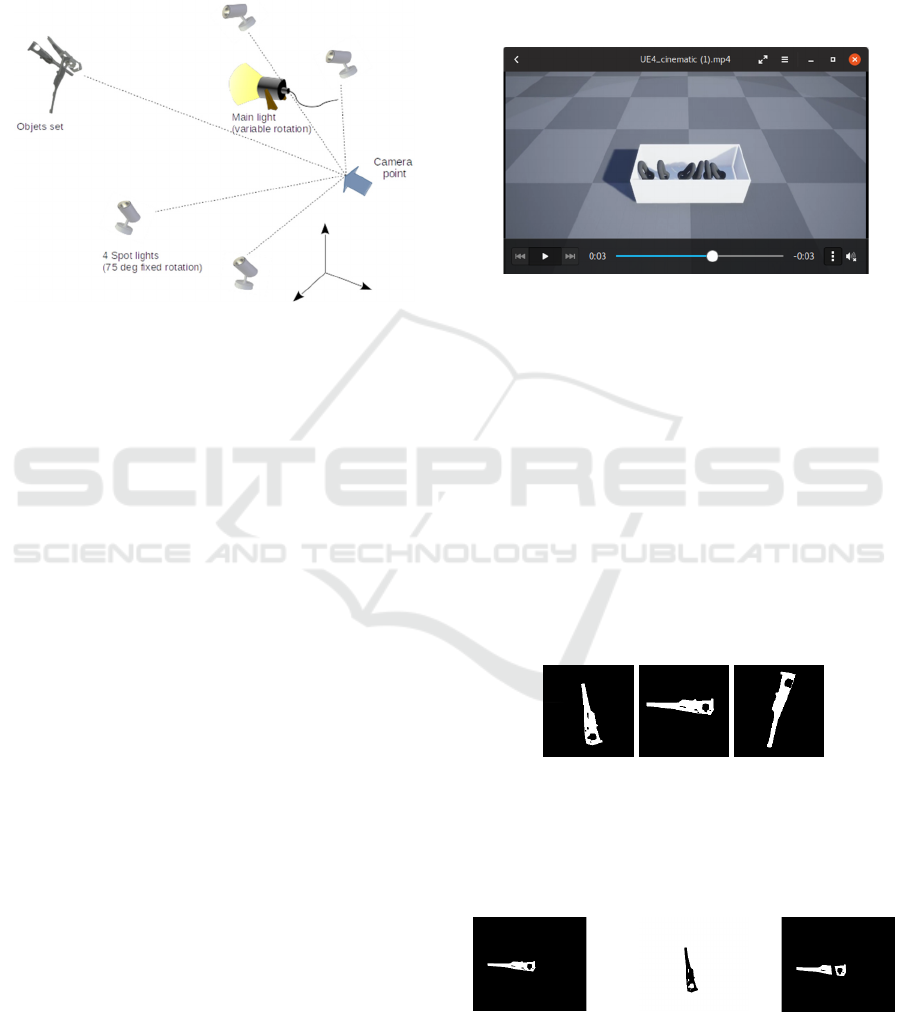
Image generation uses one primary point white
light source for general lighting: RGB intensity =
(1.0,1.0,1.0). The light source is used with a common
brightness factor 1.0, and also has the ability to set the
rotation angle relative to the camera located at a
distance equal to the removal of the camera and four
additional fixed spot light sources of low intensity
(intensity - [0.4.0.4.0.4]) spaced from the Z-axis by
angles (75,0,0) (-75,0,0) (0,75,0) (0, -75.0) without
the possibility of changing its position from the
configuration file. The primary light illuminates the
geometry of the part, highlighting its features.
Additional lighting sources compensate for "rigidity"
and provide backlight for shaded areas of details.
KMIS 2020 - 12th International Conference on Knowledge Management and Information Systems
258
The distance from the parts to the camera is
calculated as the maximum size along any axis of the
largest object, increased by 1.7. This distance varies
for each set of parts with a random additive term,
which ranges from -1/6 to 1/2 from the calculated
base distance.
Figure 1: Lighting and camera position scheme.
The Ray Tracer – POV-Ray requires a description
of the scene geometry that is automatically generated
using the jinja stencil. The fixed template is used as
the base material (which corresponds to the material
of the parts for the assembly plant in the target
project) corresponding to the white matte metal of
coarse processing (base colour < 0.64.0.687.0.71 > -
zinc, aluminium, finishing - coarse tool, anodization
with characteristics (POV-Ray meta file)
{F_MetalD} normal {agate 0.1 scale 0.1}}).
The main part is generated from the description of
a three-dimensional object in the [.obj] mesh format.
Conversion the objects into a description language of
the ray tracer – POV-Ray doing with centring the
object in the middle of its bounding box.
The initial stable position of the part is set by
fixed values of the rotation parameters, then objects
are randomized by random law without the possibility
of overlapping objects. The rotation and slope are
randomized.
In the case of solving the bin-packing problem,
the interposition of parts can be obtained by a virtual
physical experiment by using physical engines (the
engines PyBullet and Unreal4 were studied in the
work). During the simulation process, the box with
objects was "thrown" from a given height. The details
occupied a steady position under gravity force, and
the resulting 6dof coordinates of the objects could be
loaded into the ray trace module as initial values for
the trace simulation. It should be noted that physical
simulation significantly increases the number of
necessary computational operations and could be
replaced to Euler angles randomisation with
overlapping control.
In the process of image generation, each object
receives a random shift relative to its initial position
(steady position) by a distance corresponding to the
dimension of the bounding box along the x, y axes. A
fixed shift is made along the Z-axis according to the
size of the bounding box.
Figure 2: Bin-packing task physical engine example.
During the process of creating a training dataset,
the set of details is rotated by random pitch and tilt
angles, which provides different viewing angles for
the objects.
The generation of the training sample is carried
out in three stages. At the first stage, each image of
the detail is generated by the ray tracer individually
with maximum illumination. The maximum
illumination (hard light - one source with the
maximum possible intensity, illuminating an
absolutely black object without reflection) allows us
to obtain visible outlines and a detail’s mask,
regardless of the fall of the shadows of the light
source and re-reflection.
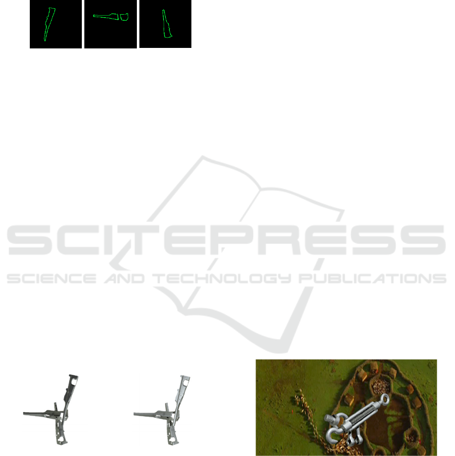
Figure 3: Details masks obtained.
The outlines are collected by masks depending on
the position of the object in the stack (masks are
subtracted) - hidden (hidden by other parts) fragments
of the outline are masked.
&
=
Figure 4: Detail batch processing.
Using the standard outline highlighting OpenCV
The Ray Tracing based Tool for Generation Artificial Images and Neural Network Training
259
approach an outline description and its bitmask are
constructed for each detail, which will then be
converted to a COCO-style (T.-Y. Lin, M. Maire, S.
Belongie, J. Hays, P. Perona, D. Ramanan, P. Dollar,
and C. L. Zitnick, 2014) (COCO – Common Objects
in Context) mask description format.
Figure 5: Detail segmentation polygons.
The description of the contours depends only on
the rotation of the details and does not depend
significantly on the position of the main light source
and is performed only once for each data set
(reflection variations).
In the second step, a total stack of objects with an
operating light intensity is collected for all specified
(from the configuration file) positions of the light
source. A stack of objects is assembled on a
transparent background with various positions of the
main illumination source. The list is set as the angle
of deviation from the camera position by enumeration
in the configuration file.
The experiments have shown that it is sufficient
to use five positions of the light source to obtain
acceptable segmentation quality results. Using the
position of the light rotated relative to the camera by
the following angles round axis: LIGHT = [[0, 0, 0],
[0, 30, 0], [0, 30, 0], [-30, -30, 0], [30, 30, 0]].
The different position of the light source allows
diversifying the picture of light and shadows as close
as possible to real images in real lighting conditions
and save computational resources for the re-
generation of the scene. Here the relative arrangement
of the parts is shown figure 7.
Figure 6: The same scene with different position of the main
light.
Therefore:
Parts will receive a random relative position
within their bounding boxes (rectangles) in x, y, and
a fixed distance z so as to avoid overlapping.
Parts will receive random rotation respecting the z-
axis (the x-axis is horizontal, the y-axis is vertical, the
z-axis is from the camera to the observer. Scene will
receive some illumination profiles. The generated set
of images is stored in the buffer directory.
After generating a set of objects and their
description, they are merged into the resulting Json-
file with COCO-style format.
In the final step, the stack of details over the
transparent background is merged with randomly
selected background images.
During the generation process, the parts will be
created with a transparent background and located in
the image directory. Random frames from arbitrary
video or specialized image storages could be used as
a random background source. We used “Home” 2009
film as the source of the video due to open access
copyright. Ffmpeg was used for frame generation.
“Home” is a 2009 documentary film by Yann Arthus-
Bertrand. It shows the diversity of life on Earth and
how humanity is threatening the ecological balance of
the planet. This film has no copyright (Yann Arthus-
Bertrand: A wide-angle view of fragile Earth | TED
Talk). Using this video is especially symbolic.
Convolutional neural networks are currently gaining
an increasingly prominent role in our lives. At the
same time, Neural Network (NN) processing is still a
very energy-consuming process. Researchers who are
working in this area have to go a long way to the
moment when these mathematical algorithms become
effective.
Based on this approach the Python-based tool has
been developed. The tool is able to generate synthetic
data sets for a batch of objects in automatic mode.
The main target of the tool presented is making
artificial images from mesh models which could be
easily implemented into a self-learning process. The
tool could be used without smart packet
dependencies.
Figure 7: Background substitution example.
The current version does not include the results of
the physical engine to estimate the position of objects
in accordance with physics and gravity. The
connection-gate with physics could be made as to the
initial position of details (zero position). Also, the
current version of the software implements the
KMIS 2020 - 12th International Conference on Knowledge Management and Information Systems
260
generation of metal objects with a matt zinc-aluminium
surface. The material could be changed in a POV-Ray
template file if it is necessary. The options of material
used will be extended in further work.
The output image size is fixed and equal to 704
by 704 pixels (octave size). Based on this resolution,
the camera position will automatically be calculated.
Parts will sequentially overlap on the images (the part
with index 0 is the lowest, the part with the highest
index is the highest).
Figure 8: Blocks flowchart.
As a result of the program running a user can get:
Annotations as separate JSON files. Each
contour and mask of the part corresponds to one
file in the directory.
Images with a transparent background;
Images with a substituted random background;
Joint COCO JSON annotation which refers to
image files. The set could be directly used for
NN training.
After generating a given number of cases, the
training sample is automatically integrated into a
single COCO-style description file.
4 EXPERIMENT AND TESTING
During the experiment, images with COCO-style
annotation data were used for СNN training.
Developed software for automatic generation of
synthetic images allows getting a dataset of annotated
images in the COCO (Common Objects in Context)
format. This format was chosen because it is one of
the most popular data formats for creating training
datasets and a lot of developers use it, too.
The Mask R-CNN (Kaiming He, Georgia
Gkioxari, P. Dollár, Ross B. Girshick, 2017) model
was used for our study. Pre-trained weights of COCO
(mask_rcnn_balloon.h5) were used as an initial state
of scales. Weights were received from the releases
page: (Mask R-CNN 2.1).
The synthetic images generated by the ray-tracing
tools were formed into training, test and validate sets.
Model training was conducted on GPU: GeForce
GTX 1080 Ti major: 6 minor: 1
memoryClockRate(GHz): 1.645. The following
model configuration was used in the computational
experiment. The training was conducted in two stages
consisting of 40 and 60 epochs with different learning
speed factors (learning rate), with different number of
network layers.
After training, we had the model on three different
datasets:
1. Exclusively using synthetic sample;
2. Exclusively on real frames;
3. On a combined sample from synthetic and real
data as a training dataset.
Three groups of weights were obtained. With
using the obtained weights the objects were detected
on new frames that did not participate in model
training.
5 ASSESSMENT OF QUALITY OF
SEGMENTATION
The result of any algorithm must be evaluated,
segmentation algorithms are not an exception.
Unfortunately, there is no hard standard on how to
estimate the quality of segmentation. But, there are
various metrics for measuring the success of the
segmentation by using the model, the work of which
is based on neural networks. We prefer to use the two
most popular methods to evaluate the work of our
model: Metric IoU (Intersection over Union)
(Rezatofighi, H., Tsoi, N., Gwak, J.Y., 2019) and
mAP (mean Average Precision) (Zhu, Mu. Recall,
2004). The results of the computational experiments
are shown in the tables below.
Table 1: Description of datasets.
Training Validation
Trained on synthetic data 1365 430
Trained on real data 200 108
Trained on mixed data
1502
137 - real data
490
60 - real data
During the computational experiment, there were
two sets of test data consisting of real shots with a
different number of frames in each set. Both datasets
for different weights were used to eliminate the
probability of getting into the test sample of frames
involved in model training.
The Ray Tracing based Tool for Generation Artificial Images and Neural Network Training
261
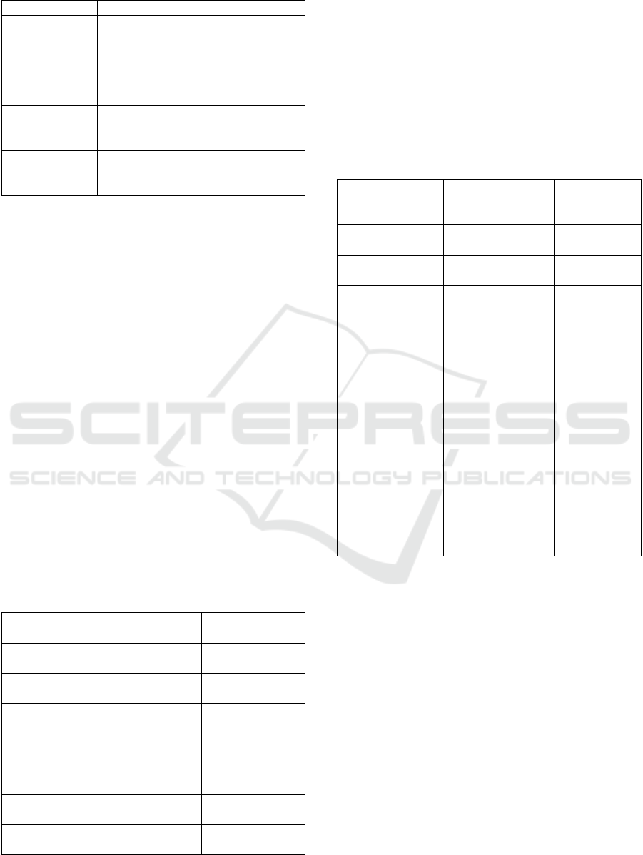
Table 2: Results of tests (metrics results).
Synthetic data Real data
Trained on
synthetic data
mAP: 0.1966
IoU: 0.8953
(108 frames)
mAP: 0.5914
IoU: 0.5460
(126 frames)
mAP: 0.507
IoU: 0.5178
Trained on real
data
mAP: 0.1664
IoU: 0.6921
(126 frames)
IoU: 0.6054
mAP: 0.8439
Trained on mixed
synthetic and real
data
mAP: 0.1960
IoU: 0.8929
(108 frames)
mAP: 0.4058
IoU: 0.6761
For weights obtained by training the model on
completely synthetic data, a test sample consisting
only of synthetic data was formed. Gaussian, Median,
and convolutional matrix-based filters with different
steps were applied to the test dataset. The target of the
filter based experiment was to test the stability of
detection and to estimate the role of thick details in
source data during the detection process. We
intended to test the stability of the segmentation
algorithm under various conditions, such as image
distortion, change in sharpness and contrast. An
annotation file of the original segmented test sample
was used in the experiment. The results are shown in
Table.
Gauss filtering is used to reduce noise in images,
and, also, blurs the boundaries of objects in the image.
The e median filter saves boundaries and raises
impulse noce. This image transformation makes it
possible to investigate the stability of the work of
segmentation algorithms under conditions of
obtaining a distorted image of lower quality.
Table 3: Effect of smoothing filters on detection testing on
real data.
Filter (window
size)
Trained on real
data
Trained on
synthetic data
Original image
mAP: 0.8440
IoU: 0.6055
mAP: 0.5071
IoU: 0.5178
Gaussian
smoothing(3, 3)
mAP: 0.8136
IoU: 0.5903
mAP: 0.3105
IoU: 0.4727
Gaussian
smoothing(5, 5)
mAP: 0.7660
IoU: 0.5568
mAP: 0.1819
IoU: 0.3996
Gaussian
smoothing(7, 7)
mAP: 0.6732
IoU: 0.4932
mAP: 0.1118
IoU: 0.3981
Median
smoothing(3,3)
mAP: 0.8186
IoU: 0.5963
mAP: 0.3743
IoU: 0.4890
Median
smoothing(5,5)
mAP: 0.7948
IoU: 0.5736
mAP: 0.2153
IoU: 0.4581
Median
smoothing(7,7)
mAP: 0.6697
IoU: 0.4914
mAP: 0.1366
IoU: 0.4112
An experiment was conducted to identify the
effect of filtration on the operation of segmentation
algorithms with weights obtained by training the
model on real images and on a mixed data set.
The influence of brightness, contrast and
sharpness of the image was also investigated in order
to verify the operability of the segmentation
algorithm work with using different technical devices
with various optical indicators.
Table 4: The experiment is a change in brightness with
training on real data.
Conditions
Weights trained on
real data
Weights trained
on synthetic
data
Brightness:0.8
mAP: 0.8343
IoU: 0.5965
mAP: 0.4268
IoU: 0.5251
Brightness:0.9
mAP: 0.8466
IoU: 0.5977
mAP: 0.4848
IoU: 0.5087
Brightness:1
(original)
mAP: 0.8439
IoU: 0.6055
mAP: 0.5071
IoU: 0.5178
Brightness:1.1
mAP: 0.8500
IoU: 0.6049
mAP: 0.5132
IoU: 0.5082
Brightness:1.2
mAP: 0.8491
IoU: 0.5875
mAP: 0.4905
IoU: 0.5121
CLAHE (Contrast
Limited Adaptive
Histogram
Equalization)
mAP: 0.8006
IoU: 0.5754
mAP: 0.3889
IoU: 0.4985
SHARPEIN
[0, -1, 0],
[-1, 5, -1],
[0, -1, 0]
mAP: 0.7863
IoU: 0.5732
mAP: 0.3933
IoU: 0.4439
SHARPEIN
[-1, -1, -1],
[-1, 9, -1],
[-1, -1, -1]
mAP: 0.5615
IoU: 0.4586
mAP: 0.1599
IoU: 0.2652
6 TARGET SYSTEM
APPLICATION
The target project is an experimental set that is
equipped by the KUKA robot (configured and
programmed by the participants from IWU
Fraunhofer Chemnitz), smart flexible gripper
(developed by the Technical University of Sofia) and
Intel RealSense D415 camera on the gripper body.
The system is located in the experimental library
IWU Fraunhofer Chemnitz.
One of the goals of this project is the development
of a method for making a decision on the optimal way
to grasp the object and move it. To solve this problem,
algorithms have been developed that allow
KMIS 2020 - 12th International Conference on Knowledge Management and Information Systems
262
recognizing and localizing an object in a three-
dimensional space and evaluating 6DoF objects.
Object recognition in the observed scene is based
on a convolutional neural network, which allows
semantic segmentation of objects in the image.
The convolutional neural network was trained
using 1000 artificial made images in train set and 430,
360 for validation and test as well.
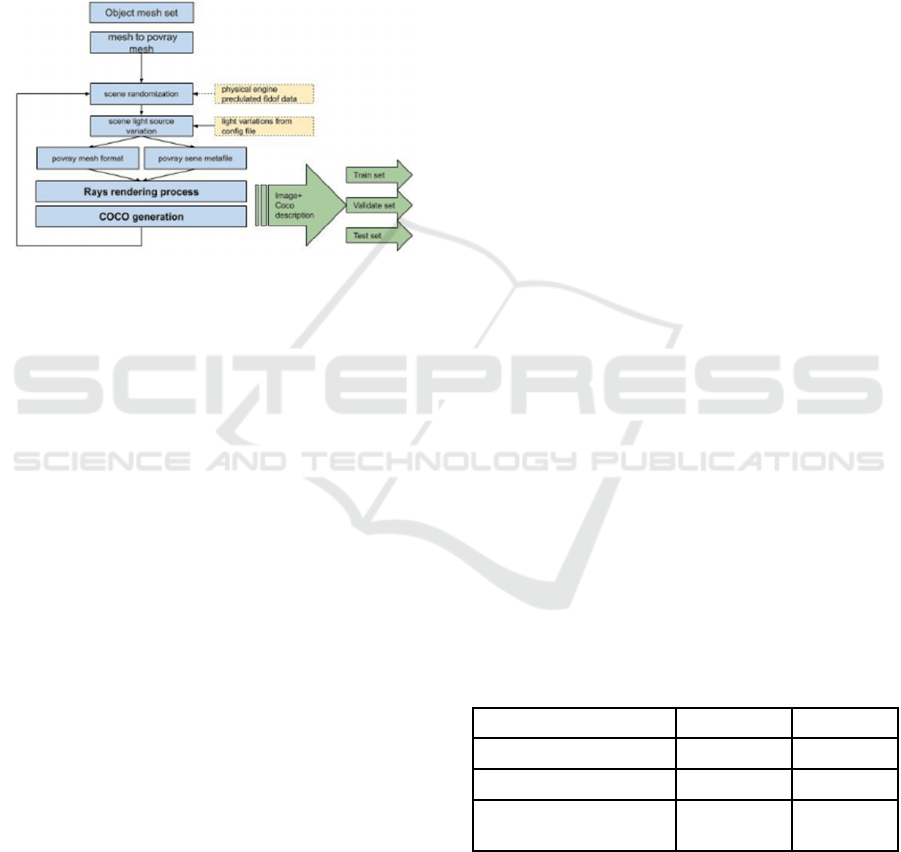
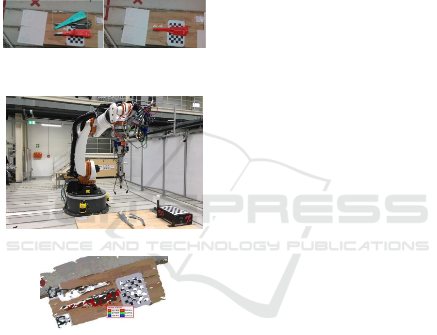
Figure 9: Real image semantic segmentation example
during integration experiment (camera is mounted on the
robot gripper body).
Figure 10: Kuka based experimental set.
Figure 11: Example of the results of 6DoF.
When the results of the objects’ segmentation in
the image are obtained, a 3D semantic objects’
segmentation in the scene is performed. Thus, the
general 3D cloud of scene points of a three-
dimensional points set of recognized objects is
selected.
This reduces the size of the 3D point cloud, which
in turn leads to an increase in the performance of the
6DoF object estimation algorithm.
The 6DoF estimation procedure has been made by
the method proposed in the work of Bertram Drost
and Slobodan Ilic (Drost, Bertram, and Slobodan Ilic,
2012).
We have got the 0.75 success of the final step -
6DoF estimation (with an accuracy of +/- 5 degrees -
the requirement for the target task: successful
grasping) during the preliminary experiment. The
6dof experiment was carried out using the parts of the
target set (parts for car assembly) at IWU Fraunhofer
laboratory bench consisting of KUKA manipulator,
universal grip, IntelRealsense D415 camera mounted
on the robot arm. Fig. shows an example of the results
of 6DOF.
The gripper is designed to provide maximum
grasping flexibility regarding the geometry of the
objects and their relative position. The flexibility is
achieved by the separate or joint action of two
systems – mechanical and pneumatic. The
mechanical one consists of two fingers which are
mechanically actuated and equipped with fingertips
allowing for a safely grasping of a wide range of
objects. The pneumatic system provides a vacuum
based grasping in case of convex or concave surfaces.
7 CONCLUSIONS
Using exclusively synthetic data (obtained by
developed algorithms and by using created software
modules) for training allows us to ensure acceptable
quality of segmentation real data frames in the range
of 50-60%. In joint batch segmentation (processing a
scene from different angles by obtaining data from a
video camera attached to a robot arm), the success of
segmentation can be greatly increased. The metrics in
this mode will be refined in the next step during the
calculation experiment at IWU Fraunhofer.
The mAP metric does not adequately reflect
segmentation results and should be excluded from
consideration.
Studies of stability (influence of digital filters on
initial images) of developed algorithms have been
carried out. Results of research of the use of digital
filters (linear - convolution, nonlinear - work with
histograms, median filtration), show stability (limit of
stability) of procedures of segmentation. The physical
interpretation of these results consists of the "not
ideal" recording of data in the conditions of operation
of the robotic stand (blurring and distortion of the
picture as a result of the movement of objects and
camera, a variation of illumination). Segmentation
technologies showed low sensitivity to brightness
variation within gamma correction 0.8 - 1.2 (IoU
deviation was about 4%), which confirms the
accuracy of solutions for the generation of training
samples listed in items 1.2 of the main report.
The Ray Tracing based Tool for Generation Artificial Images and Neural Network Training
263

The system showed significant sensitivity to
smoothing filters (for the Gauss 3x3 filter, the IoU
drop was 9% further for the 5x5 by another 14%). The
fact of stabilization IoU with a further increase of
smoothing is interesting, which suggests that the
contribution of thin details of images gives an
increase of segmentation quality by a quarter).
Applying median filters to the original image does not
win as a segmentation.
The tool developed could be used for making
fully synthetic trained databases for CAD-described
objects instead of real images.
8 THE FURTHER WORK
Unknown objects issue. The algorithms developed
could be extended to unknown (the information about
the model of object and material made are
unavailable). The problem: the depth sensor used
(Intel Realsense I415 family) is not able to take the
data cloud like a 3d scanner. Possible solution is: the
system should be equipped with a 3d scanning sensor
which is able to take the right PointCloud picture.
The current realization of the artificial image
generation tool is possible with aluminium, zincum,
and steel details made of one material. It is necessary
to extend its use to other materials (POV-Ray
material library could be used).
The tool developed generates mask-based
annotation together with polygonal annotation.
During experiments presented the second only type
used for training.
ACKNOWLEDGEMENTS
This work has been accomplished with financial
support by RFBR project No 18-58-76003 in frames
of European program ERA.Net RUS PLUS 2017-
294.
REFERENCES
Eric Haines and Tomas Akenine-Möller, 2019. Ray Tracing
Gems High-Quality and Real-Time Rendering with
DXR and Other APIs
[Online] The Ultimate Guide to Synthetic Data in 2020
Available: https://blog.aimultiple.com/synthetic-data/
John B. McCormac, 2018. “SLAM and Deep Learning for
3DIndoor Scene Understanding”
Hans Krupakar, 2018. COCO-Style-Dataset-Generator-
GUI [Source code]: https://github.com/andytung2019/
COCO-Style-Dataset-Generator-GUI
Hans Krupakar, 2018. COCO-Style-Dataset-Generator-
GUI [Source code]: https://github.com/hanskrupakar/
COCO-Style-Dataset-Generator-GUI
J. Tremblay, T. To, A. Molchanov, S. Tyree, J. Kautz, S.
Birchfield, 2018. Synthetically Trained Neural
Networks for Learning Human-Readable Plans from
Real-World Demonstrations. In International
Conference on Robotics and Automation (ICRA)
J. Tremblay, T. To, S. Birchfield, 2018. Falling Things: A
Synthetic Dataset for 3D Object Detection and Pose
Estimation. CVPR Workshop on Real World
Challenges and New Benchmarks for Deep Learning in
Robotic Vision
[Online] POV-Ray – The Persistence of Vision Raytracer
Available: http://www.povray.org/
[Online] POV-Ray: Download Available:
http://www.povray.org/download/
[Online] POV-Ray: Hall of Fame, Available:
http://hof.povray.org/
T.-Y. Lin, M. Maire, S. Belongie, J. Hays, P. Perona, D.
Ramanan, P. Dollar, and C. L. Zitnick, 2014. Microsoft
COCO: Common Objects in Context in ECCV
[Online] COCO – Common Objects in Context, Available:
https://cocodataset.org/#format-data
[Online] Yann Arthus-Bertrand: A wide-angle view of
fragile Earth | TED Talk, Available:
https://www.ted.com/talks/yann_arthus_bertrand_a_wi
de_angle_view_of_fragile_earth#t-4732
Kaiming He, Georgia Gkioxari, P. Dollár, Ross B. Girshick,
2017. Mask R-CNN in ICCV
Waleed, 2018. Mask R-CNN 2.1 [Source code]
https://github.com/matterport/Mask_RCNN/releases/ta
g/v2.1
Rezatofighi, H., Tsoi, N., Gwak, J. Y., 2019. et al.:
Generalized intersection over union: a metric and a
loss for bounding box regression, arXiv preprint
Zhu, Mu. Recall, 2004. Precision and average precision
Drost, Bertram, and Slobodan Ilic, 2012. 3d object
detection and localization using multimodal point pair
features, 2012 Second International Conference on 3D
Imaging, Modeling, Processing, Visualization &
Transmission, IEEE
KMIS 2020 - 12th International Conference on Knowledge Management and Information Systems
264
