
Deployment of Multi-agent Pathfinding on a Swarm of Physical Robots
Centralized Control via Reflex-based Behavior
J
´
an Chud
´
y, Nestor Popov and Pavel Surynek
a
Faculty of Information Technology, Czech Technical University in Prague,
Th
´
akurova 9, 160 00 Praha 6, Czechia
Keywords:
Multi-Agent Pathfinding (MAPF), Deployment, Desynchronization, Swarm of Robots, Reflex-based Control.
Abstract:
Multi-agent pathfinding is a problem of finding paths for multiple agents from their initial configuration to their
goal configuration that results in a plan execution without collisions. In this paper, we deploy MAPF solutions
on a swarm of small mobile robots. During the plan execution, we mitigate the problem of desynchronization
that comes with the plan execution on physical hardware using the reflex-based behavior of the robots. Such
deployment can help researchers and educators to demonstrate and test their findings in the physical world.
The robot has a line-following capability that can be used for simulation of discrete MAPF solutions. The
control curves are displayed in real-time on a display on which the robots move during their path execution.
A prototype of the deployment was built and tested experimentally.
1 INTRODUCTION
Multi-agent pathfinding problem (MAPF) is the task
of finding a plan that navigates multiple agents in an
environment from their initial positions to their goal
positions without them colliding during the execution
(Kornhauser et al., 1984; Ryan, 2008; Sharon et al.,
2015; Sharon et al., 2013; Silver, 2005; Surynek,
2009; Wang and Botea, 2011). The environment is
usually modeled as an undirected graph G = (V, E) in
which the agents move. In each vertex of G at most
one agent is placed, and they can move across edges
of the graph. At each time step agent can either wait
in the current vertex or move to a neighboring one
that is unoccupied. Some additional problem-specific
models and constraints may be used for various appli-
cations.
Due to its real-world applications, MAPF has been
a deeply researched topic over recent years. New
variations of this problem and approaches to solving
them, emerged, and new solving algorithms have been
designed. Many practical problems from robotics can
be interpreted as MAPF. Examples include item re-
arrangement in automated warehouses (Basile et al.,
2012), ship collision avoidance (Kim et al., 2014), or
formation maintenance and maneuvering of aerial ve-
hicles (Zhou and Schwager, 2015).
a
https://orcid.org/0000-0001-7200-0542
Crossing the gap between a virtual simulation of
MAPF and physical hardware execution is not an
easy task. Deployment in the physical world comes
with additional problems and constraints for the sys-
tem, and specialized solutions are often developed for
these applications. Using existing solutions on phys-
ical robots is usually unattainable since most of the
MAPF solutions produce discrete plans, and robotic
hardware moves continuously in a continuous envi-
ronment. The additional problem is that these solu-
tions do not account for problems like desynchroniza-
tion that occur in these physical deployments.
1.1 Contribution
This paper describes the deployment of discrete
MAPF solutions on a swarm of small mobile robots–
Ozobot Evo. Ozobot robots have a line following
capabilities and are also programmable. The use of
discrete MAPF models and limited hardware of the
robots makes the system prone to desynchronization.
We used the reflex-based behavior of the robots to
control them on a surface of a display and mitigate
the desynchronization. The navigation of the robots
is provided by control curves that are displayed un-
derneeth the robots during their plan execution.
This deployment brings a new approach to mitiga-
tion of desynchronization during plan execution and
the execution of existing MAPF solutions on physical
28
Chudý, J., Popov, N. and Surynek, P.
Deployment of Multi-agent Pathfinding on a Swarm of Physical Robots Centralized Control via Reflex-based Behavior.
DOI: 10.5220/0010105800280038
In Proceedings of the International Conference on Robotics, Computer Vision and Intelligent Systems (ROBOVIS 2020), pages 28-38
ISBN: 978-989-758-479-4
Copyright
c
2020 by SCITEPRESS – Science and Technology Publications, Lda. All rights reserved
robots. Our contribution could also help researchers
and educators to demonstrate theoretical MAPF solu-
tions in the physical world.
The paper is organized as follows. First, we in-
troduce MAPF formally and recall major solving al-
gorithms. Then Ozobot Evo, a robot we use for sim-
ulation, is introduced. The previous MAPF deploy-
ment strategy on Ozobot is shortly described and used
to test the susceptibility of the robot’s hardware for
desynchronization. Then we introduce a new strategy
for MAPF deployment on the swarm of Ozobot Evo
robots through reflex-based control, focusing on the
mitigation of desynchronization. In the end, the im-
plemented prototype is experimentally evaluated on
various MAPF benchmarks, and the results are sum-
marized.
2 OVERVIEW OF MAPF
Almost all previous MAPF research and proposed
solvers were built on top of several assumptions about
time. First, time is not continuous, but rather dis-
cretized into time steps. Second, all actions that
agents perform take the same amount of time to ex-
ecute, precisely one time step. Moreover, a signifi-
cant portion of the research was done on simple grid
graphs, and agents are usually entities of the same
shape and size that fit into one graph vertex. In (An-
dreychuk et al., 2019), the authors propose an algo-
rithm that supports continuous time and agent actions
of different durations. Agents even can have different
speeds. The collision detection is geometry-aware so
that the algorithm can handle agents of different sizes
and shapes. The algorithm is optimal and complete.
Generally, there are three major categories of
MAPF solvers–search-based, reduction-based, and
rule-based. In the search-based category are algo-
rithms like CBS (Sharon et al., 2015) and its improved
variants (Boyarski et al., 2015), ICTS (Sharon et al.,
2013), or other algorithms based on A*. Reduction-
based solvers reduce the MAPF problem instance to
an instance in a different paradigm for which an effi-
cient solver exists. These solvers utilize reduction to
SAT
2
problems (Surynek, 2012), answer set program-
ming (Erdem et al., 2013) or integer linear program-
ming (Yu and LaValle, 2013). Rule-based solvers
work with specific agent movement rules, and ex-
amples are the algorithms Push-and-Swap (Luna and
Bekris, 2011a), BIBOX (Surynek, 2009), and Push-
and-Rotate (de Wilde et al., 2014).
Some other approaches have also been researched
2
Boolean satisfiability
over the last years. Opposed to the cooperative
pathfinding (CPF) (Silver, 2005; Jansen and Sturte-
vant, 2008), which is the same concept as the classi-
cal MAPF, where agents aim to fulfill one global goal
as effectively as possible, there is adversarial coop-
erative pathfinding
3
(ACPF) (Ivanov
´
a and Surynek,
2013). In ACPF, agents are divided into a finite num-
ber of teams that alter in turns between time steps.
The goal of ACPF is to find a winning solution for
one selected team of agents that reacts to moves of
other, adversarial, groups of agents. Additionally,
ACPF can follow different tactics like offense or de-
fense. The adversarial approach to MAPF provided
additional opportunities for future research.
2.1 Classical Discrete MAPF
The classical MAPF problem (Silver, 2005; Ryan,
2008) consists of an undirected graph G = (V, E) and
a set of agents A = {a
1
, a
2
, ..., a
k
} such that |A| < |V |.
Agents are placed in the vertices so that at most one
agent resides in each vertex. The configuration of
agents is denoted α : A → V . Next, we are given the
initial configuration of the agents α
0
and goal config-
uration α
+
.
At each time step of the solution, every agent has
two possible actions from which it can choose. The
agent can either wait in its current vertex or move to
one of the neighboring vertices if the move is allowed.
In classical MAPF, these are the only two actions that
agents can perform. The task is to find a sequence of
such actions for each agent a
i
that moves the agent
from α
0
(a
i
) to α
+
(a
i
) such that agents do not collide,
i.e., do not occupy the same vertex simultaneously.
Typically, an agent can enter only currently unoccu-
pied vertices. In other words, moving into a vertex,
from which another agent is leaving, is not considered
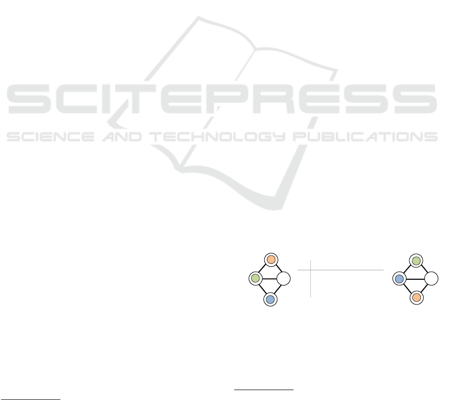
an allowed move. An example of a MAPF instance is
shown in Figure 1.
α
+
α
0
A
a
1
a
2
a
3
a
1
a
2
a
3
α
0
α
1
α
2
α
3
α
4
= α
+
A C C C D
B B A
A
A
D D D B B
B
C
D
A
a
1
a
2
a
3
B
C
D
Figure 1: A MAPF instance with three agents a
1
, a
2
, and
a
3
.
Below, we define a move-to-unoccupied variant of
MAPF, where agents are allowed to move only to un-
occupied vertices.
3
Adversarial cooperative pathfinding can also be re-
ferred to as adversarial pathfinding or adversarial MAPF.
Deployment of Multi-agent Pathfinding on a Swarm of Physical Robots Centralized Control via Reflex-based Behavior
29

Definition 1. (Move-to-unoccupied MAPF). Con-
figuration α
0
results from α if and only if the following
conditions hold:
(i) α(a) = α
0
(a) or {α(a), α
0
(a)} ∈ E for all a ∈ A
(agents wait or move along edges);
(ii) for all a ∈ A it holds that if α(a) 6= α
0
(a) ⇒
α
0
(a) 6= α(a
0
) for all a
0
∈ A (target vertex must be
empty);
(iii) and for all a, a
0
∈ A it holds that if a 6= a
0
⇒
α
0
(a) 6= α
0
(a
0
) (no two agents enter the same tar-
get).
Solving the MAPF instance is to find a sequence
of configurations [α
0
, α
1
, ..., α
µ
] such that α
i+1
results
using valid movements from α
i
for i = 1, 2, ..., µ − 1,
and α
µ
= α
+
. A feasible solution of a solvable MAPF
instance can be found in polynomial time (Wilson,
1974; Kornhauser et al., 1984). Precisely, the worst-
case time complexity of most practical algorithms for
finding feasible solutions is O(|V |
3
) (asymptotic size
of the solution is also O(|V |
3
)) (Luna and Bekris,
2011b).
2.1.1 Cumulative Objectives in MAPF
Two standard objective functions are being used–
makespan and the sum-of-costs. In the makespan ob-
jective (Surynek, 2017), we need to minimize µ in the
solution sequence mentioned above. In our solution,
we use solvers that implement the sum-of-costs ob-
jective (Dresner and Stone, 2008; Sharon et al., 2013;
Sharon et al., 2015):
Definition 2. The Sum-of-costs objective is the
summation of the number of time steps each agent
requires to reach its goal vertex. Denoted ξ =
∑
k
i=1
ξ(path(a
i
)), where ξ(path(a
i
)) is an individual
path cost of agent a
i
connecting α
0
(a
i
) calculated as
the number of edge traversals and wait actions.
4
Observe that we accumulate the cost of wait ac-
tions for agents not yet located in their goal vertices
in the sum-of-costs objective. We note that finding an
optimal (minimal) solution with respect to the sum-
of-costs objective is NP-hard (Ratner and Warmuth,
1986). Therefore, using search as we do here to solve
MAPF optimally is currently the only viable option.
2.2 Real-world Complications
There is a gap between the theoretical MAPF mod-
els and deployment in the physical world. This gap
4
The notation path(a
i
) refers to a path in the form of
a sequence of vertices and edges connecting α
0
(a
i
) and
α
+
(a
i
), while ξ assigns the cost to a given path.
consists of the already mentioned assumptions about
time and the agents, but also the way how the environ-
ment is modeled is problematic. Usually, we model
the environment as a tiled grid or undirected graph,
but for example, maps in some video games benefit
from not being grid-based but instead use polygons
(Botea et al., 2013).
Some studies (Li et al., 2019; Andreychuk et al.,
2019) considered the geometrical shape and size of
the agents, geometry-aware collision detection, and
various movement speeds. Also, continuous move-
ments of the agents are used in order to simulate real-
istic robot movement in a physical environment.
Another assumption of theoretical models is that
all agent movements are synchronous, but in reality,
there can be many factors that might introduce desyn-
chronization into the plan execution. One of these fac-
tors is the mentioned variety of actions durations. Be-
cause every agent is executing a different sequence of
actions, their movements are desynchronized quickly.
Fortunately, this factor can be mitigated using a suit-
able abstract solver, but many factors cannot be antic-
ipated. Some monitoring of the execution is needed
when weather, terrain, or other unexpected circum-
stances might cause desynchronization. The ability
of an agent to follow the planned path successfully
can be dependant on the environment or its hardware.
The abstract plans should account for unexpected
mistakes and delays to prevent unexpected collisions,
which can have more significant consequences in the
physical world than in the virtual environment. For
this, k-robustness (Atzmon et al., 2018) can be intro-
duced to the plan. A k-robust plan, besides the classi-
cal MAPF plan, requires that no other agent can enter
it for the next k time steps after an agent leaves a posi-
tion. If agents were to move in a train-like formation,
there would be empty spaces between them.
2.3 CBS Algorithm
The Conflict-based Search (Sharon et al., 2015) is a
two-level optimal MAPF algorithm that decomposes
the MAPF problem into several constrained single-
agent pathfinding problems that are easier to solve.
The algorithm is composed of two searches–high-
level search and low-level search.
The high-level search is performed on a binary
constraint tree that is expanding during the search un-
til a valid solution is found. Each node of the con-
straint tree holds a set of constraints, a found solution,
and a cost. All constraints are tuples (a
i
, v, t), meaning
that the agent a
i
cannot be at the vertex v at time step
t. Each node inherits the set of constraints from its
parent and adds only one extra constraint for a spe-
ROBOVIS 2020 - International Conference on Robotics, Computer Vision and Intelligent Systems
30

Algorithm 1: High-Level search of CBS algo-
rithm.
Input: MAPF problem instance Σ
1 R.constraints ←
/
0;
2 R.solution ← paths from low-level search;
3 R.cost ← cost(R.solution);
4 insert R into OPEN;
5 while OPEN 6=
/
0 do
6 N ← node from OPEN with lowest cost;
7 validate N.solution until conflict;
8 if N.solution has no conflicts then
// it is a valid solution
9 return N.solution
10 C ← first conflict (a
i
, a
j
, v, t) found in
N.solution;
11 foreach a in {a
i
, a
j
} do
12 N
0
← new constraint tree node;
13 N
0
.constraints ← N.constraints ∪
{(a, v, t)};
14 N
0
.solution ← N.solution;
15 update N
0
.solution for agent a with
low-level search;
16 if N
0
.solution was found then
17 N
0
.cost ← score(N
0
.solution);
18 insert N
0
into OPEN;
cific agent. The solution in a node is a set of paths
for all agents found by the low-level search. Each of
the paths is restricted by the constraints for the given
agent. The cost of the node is the cost of the found
solution. In Algorithm 1, the pseudocode of the high-
level search of CBS is shown. At the beginning of
the search, the root of the constraint tree is initialized.
The set of constraints in the root node is empty, and
the solution is a set of shortest paths for each agent.
The tree is searched in a best-first manner, meaning
that the lowest-cost node from the open nodes is pro-
cessed and expanded in each iteration. A solution of
the currently processed node is checked for conflicts
between agents in their paths. If there is no conflict,
the solution is valid, and these paths are returned. If a
conflict is found, two new constraints are added to the
constraint tree for this conflict. The conflict is a tuple
(a
i
, a
j
, v, t), meaning that both agents a
i
and a
j
occupy
vertex v at time step t. The node is split into two child
nodes, each introducing a new constraint for one of
the conflicted agents and holding an updated solution.
For example, for agent a
i
, a new constraint (a
i
, v, t) is
added. Then the path of the agent a
i
from the pre-
vious solution is replanned with the low-level search
that uses the new set of constraints. If the low-level
search founds a valid path for this agent, the node is
Figure 2: Ozobot Evo robot (photo from (Evollve, Inc.,
2020a)).
added to the set of open nodes.
The low-level search performs a simple single-
agent pathfinding search for a given agent while mak-
ing sure the solution does not break any constraints
concerning the agent. In this low-level of CBS, any
optimal single-agent pathfinding algorithm can be
used. The constraints that the algorithm needs to han-
dle ensure that none of the previously-detected con-
flicts in the high-level search is repeated in the new
path.
3 ROBOTIC AGENT: OZOBOT
EVO
In our deployment of MAPF solutions, we use a
swarm of small mobile robots–Ozobot Evo (Evollve,
Inc., 2020b). An image of the Ozobot Evo robot is in
Figure 2. It is equipped with a considerable amount of
sensors and other hardware, as can be seen in a visual
breakdown of the robot in Figures 3 and 4.
The primary capability of Ozobot Evo is to follow
lines, which is also its default reflex behavior. This
behavior can also be altered using Color Codes or
OzoBlockly. Color Codes are instruction markers that
can be read and executed by Ozobot, and OzoBlockly
is a visual code editor where the user can control al-
most all of the robot’s hardware. It is more affordable
to build a swarm from Ozobot Evo robots compared
to other conventional mobile robots used in research.
However, Ozobot is more limited in terms of func-
tionality and hardware.
3.1 Hardware and Movement
Ozobot can move around using its motor and wheels.
By turning the wheels separately at different speeds,
it can turn and follow curved trajectories. Under the
base of the Ozobot are several line sensors and an op-
tical color sensor. The purpose of the sensors is to de-
Deployment of Multi-agent Pathfinding on a Swarm of Physical Robots Centralized Control via Reflex-based Behavior
31
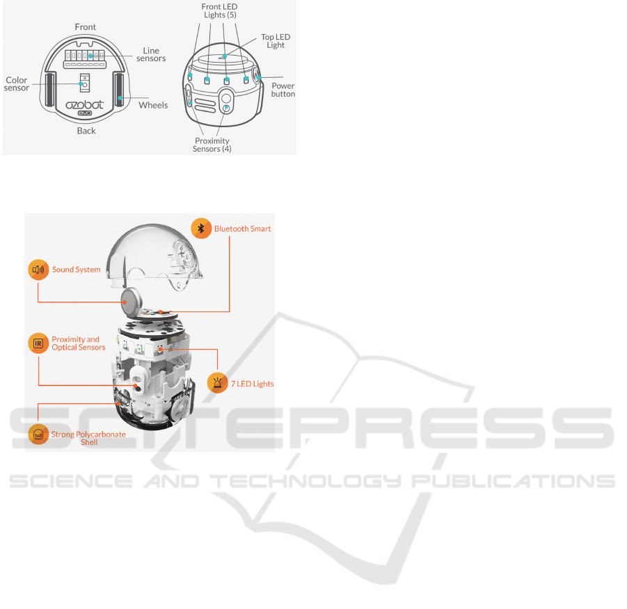
Figure 3: Sensor layout of Ozobot Evo (photo from (Evol-
lve, Inc., 2020c)).
Figure 4: Breakdown of Ozobot Evo (photo from (Evollve,
Inc., 2020c)).
tect lines and surface color. The color sensor can dis-
tinguish eight different colors, and Ozobot is highly
dependant on it because it allows the robot to read
Color Codes. It is also used to load programs into the
Ozobot’s memory.
The essential reflex functionality of Ozobot we
used in our deployment is line following. By default,
Ozobot follows lines at a speed of 30 mm/s. The
robot can detect line intersections, where it chooses
one of the possible directions at random. It is impor-
tant to know that Ozobot does not register a 90-degree
turn as an intersection. Ozobot can follow lines either
on a paper or on display, and it can also transfer be-
tween different surfaces. If the robot loses the line
it is following, it stops its motion. While following
lines, Ozobot will also read and execute Color Codes
if found.
The hardware of the robot is fairly limited, and
different line properties, like line thickness or angle
of turns, need to be set correctly for accurate detec-
tion and following. It is also recommended to cali-
brate Ozobot before every use to ensure the correct
functionality of its optical sensors.
4 DEPLOYMENT STRATEGIES
The previous solution of discrete MAPF solution
deployment on physical robots from (Bart
´
ak et al.,
2018) worked well for direct comparison of MAPF
models. In their deployment, the authors trans-
lated found solutions into the Ozobot’s movement
primitives that can be loaded into the robot as an
OzoBlockly program. Rotation actions had to be in-
cluded in the abstract model, and it was ensured that
all actions have the same duration. Each Ozobot with
its individual path was then placed on a grid map
printed out on a paper, where the plan execution was
performed.
Because of how this strategy utilizes Ozobots,
there are several drawbacks that could be solved using
a different deployment strategy:
• It is unattainable to start the plan execution syn-
chronously for a large number of robots since the
execution is started manually.
• Robots need to be individually reprogrammed be-
fore deployment on a new problem instance.
• Abstract models and MAPF solvers need to be
modified in order to use them for this deployment.
In our deployment strategy, we use Ozobots as
purely reflex-based agents with a fixed behavior. The
agents navigate in an environment that can output in-
formation for them, affecting their behavior. In our
case, the environment is a surface of a display on
which the Ozobots can move. Their paths are dis-
played underneath them as control lines the robots
can follow. The plans are obtained from a discrete
centralized MAPF solver and then processed for the
displaying on the screen.
4.1 Expected Problems
Even if the MAPF solver finds a valid solution, colli-
sions can still occur if the environment is modeled in-
correctly. Sufficient space between positions needs to
be ensured so the robots can move around each other
without any contact.
The biggest issue is the desynchronization of the
plan execution. This problem can be caused, for ex-
ample, by the limited hardware of the robots. Since
the actions of robots in our deployment do not have
the same duration, the path execution will desynchro-
nize very quickly. In order to perform a successful
plan execution, we need to mitigate the desynchro-
nization problem and have the agents to self-correct
their position on their individual paths.
ROBOVIS 2020 - International Conference on Robotics, Computer Vision and Intelligent Systems
32
5 HARDWARE
DESYNCHRONIZATION
To test if the Ozobot’s hardware is prone to cause
desynchronization by itself, we implemented similar
deployment as in (Bart
´
ak et al., 2018). Maps repre-
senting different problem instances are printed out on
paper on which Ozobots can move. We implemented
a modified version of the CBS solver to support robot
rotation as actions in planned paths. The individual
paths of the found solutions are translated into the fol-
lowing movement primitives:
• Follow the line to the next intersection (forward
movement);
• rotate 90 degrees left;
• rotate 90 degrees right; and
• wait.
The sequences of these actions are loaded into the
Ozobots as an OzoBlockly program and then exe-
cuted on the printed map.
To isolate the desynchronization caused by hard-
ware limitation, we had to assure that each action has
the same duration. The configuration used is in Ta-
ble 1. Each action was configured to take precisely
1.86 seconds. For the move and rotate actions, addi-
tional wait time needed to be added to assure perfect
timing.
Table 1: Ozobot action configuration.
Action Speed [mm/s] Wait time [s] Duration [s]
move 35 0.05 1.86
rotate 15 0.85 1.86
wait 0 1.86 1.86
5.1 Evaluation
This deployment was tested on five different maps,
where the execution time was compared to the com-
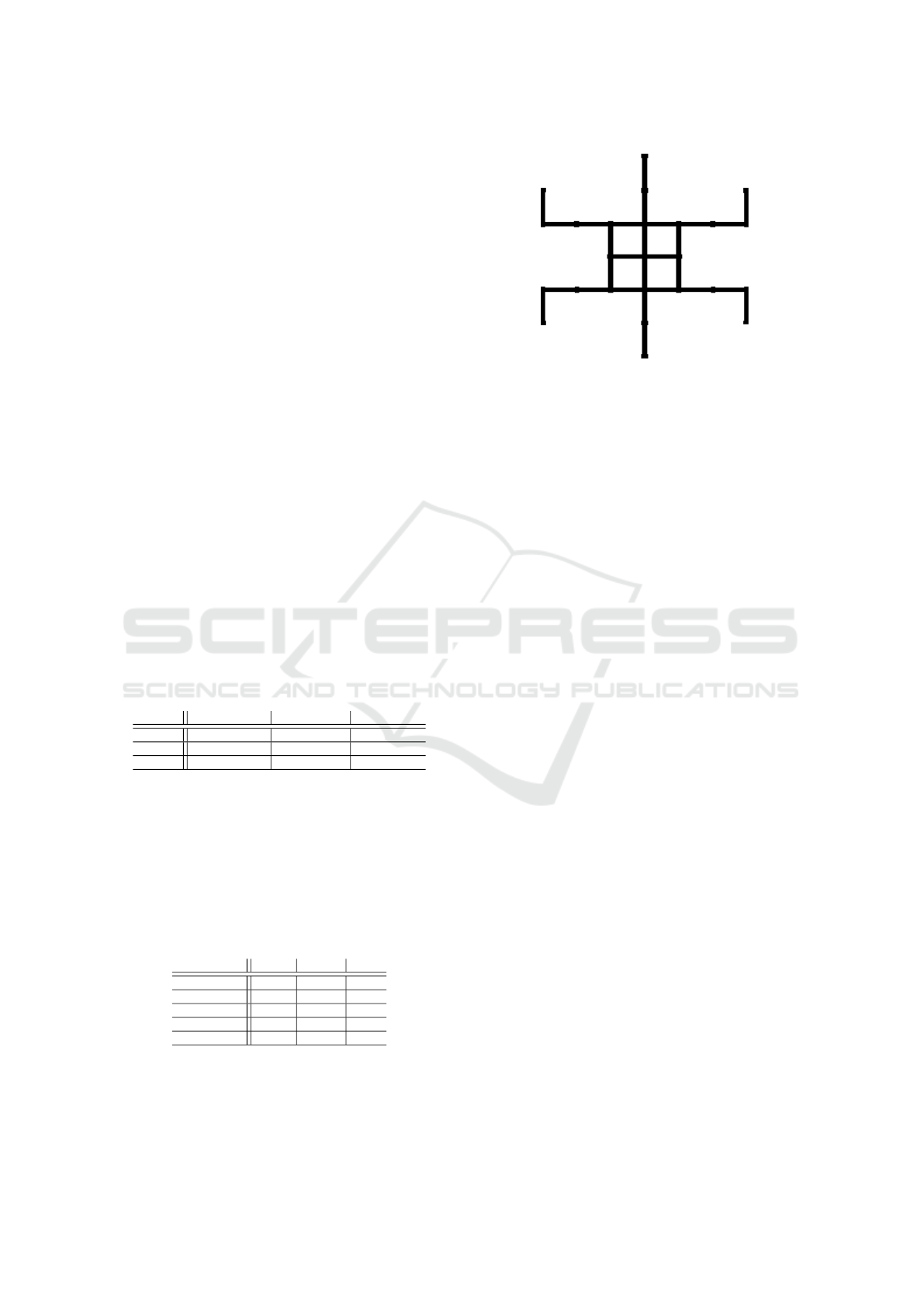
puted reference time of the plan. An example of a
map called turtle is in Figure 5.
Table 2: Average desynchronization per action and map in
milliseconds.
Map/Action Move Rotate Wait
grid 2.1 9.5 0.0
tunnel 9.0 9.5 16.8
race 6.0 2.0 11.0
roundtunnel 5.5 11.0 0.0
turtle 7.4 5.1 1.7
On each map, we measured the average desyn-
chronization for each action compared to the refer-
ence action duration. These time differences in mil-
Figure 5: An example of a map used for the desynchroniza-
tion experiment.
liseconds can be found in Table 2. The time differ-
ences of each action compared to the reference time
1.86 seconds were from interval (−154, 256) mil-
liseconds.
Overall, the desynchronization was notable, but
not large enough to cause accidental collisions be-
tween agents. No plan was executed with a time dif-
ference of more than 408 milliseconds from the ref-
erence plan duration. In more complicated plans, this
inconsistency of action duration could pose a problem
for the execution.
6 DEPLOYMENT PROTOTYPE
We have implemented a prototype of the reflex-based
deployment strategy, as explained in Section 4 in
Python. In this section, we go through some of the as-
pects of the deployment in more detail. We primarily
concentrate on the aspect of desynchronization and its
mitigation using the reflexive behavior of the agents.
The application takes a map file that contains the
MAPF problem instance we want to solve and execute
on the hardware. The solution is found by an already
existing and unmodified MAPF solver, and the plan is
processed. Both the map and paths are then displayed
on a screen on which the Ozobots are located. The
reflexive behavior of the robots had to be modified.
6.1 Environment
For our prototype, we chose to use grid-based maps,
which can be easily represented as grids of tiles on the
screen. The abstract representation of the graph, with
which the MAPF solver operates, is an undirected
graph. The abstract representation with the solution
is then converted to a drawable map that can be dis-
played in the physical environment–the surface of the
screen.
Deployment of Multi-agent Pathfinding on a Swarm of Physical Robots Centralized Control via Reflex-based Behavior
33
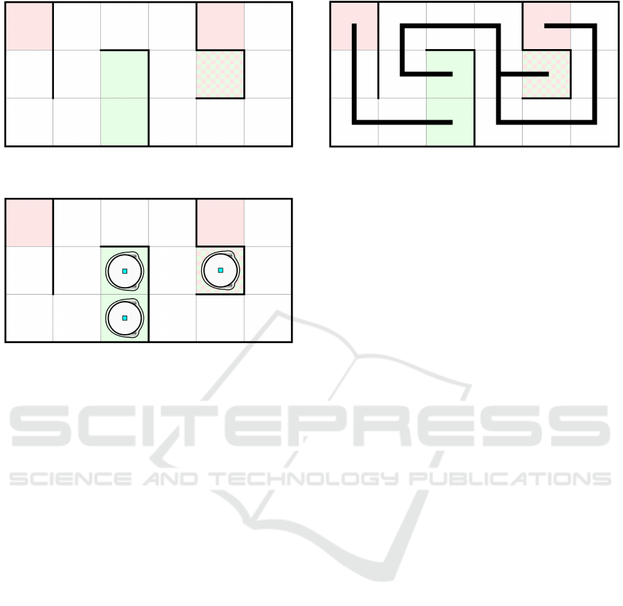
Figure 6: An example of a map displayed on the screen
before the simulation.
Figure 7: The map example with Ozobots ready to execute
paths.
An example of a map is shown in Figure 6. If
there is no edge between two neighboring vertices in
the original graph, a wall is displayed on the map be-
tween the corresponding tiles. The walls are also dis-
played all around the map to indicate the perimeter.
With green and red color, we mark tiles that represent
a start or goal position of the agents. If there is a
start and also a goal position on a single tile, the tile is
filled with both colors using a checker pattern. Note
that the colors need to have very low opacity, so as
the Ozobots do not register them as following lines.
At the beginning of the execution, Ozobots are placed
on the green tiles, as shown in Figure 7. In the end,
they should stand on the red tiles. During the execu-
tion, the planned paths are displayed underneath the
robots.
6.2 MAPF Solver
The prototype uses an already existing program that
implements the SMT-CBS algorithm (Surynek, 2019),
which combines the SAT-based solving principle and
the CBS algorithm. All algorithms in this program are
implemented under the sum-of-costs objective func-
tion.
6.3 Path Animation
To perform the path execution with Ozobots, we
need to transform the discrete solution into continu-
Figure 8: Full agent paths displayed on the map.
ous paths and display them on the map. When the
plan is displayed, Ozobots should be able to execute
their paths without any manual interference.
The simplest solution for the path outputting
would be to display the whole plan at once, as shown
in Figure 8. Unfortunately, this method introduces
a problem for Ozobots. When paths of at least two
agents cross, an intersection is created in the dis-
played following lines, where Ozobots choose their
direction randomly. Therefore, each robot would
need to memorize a sequence of directions it needs to
choose at the intersections on its path. Ozobots would
also be unable to wait in a specific position.
These problems can be solved by animating the
paths. At every moment, only a small path segment
underneath each robot is displayed. By moving the
path segment, Ozobot should always have a line to
follow. However, when following the paths, Ozobot
does not have a constant speed because of turns.
Therefore the plan execution of the swarm desynchro-
nizes, and we cannot be sure where the robots are lo-
cated at a given moment. The main issue is that if a
robot moves too slow, it will lose the path segment,
and if it moves too fast, it can lose it at a turn.
6.3.1 Reflexive Synchronization
We use reflexive behavior to mitigate the desynchro-
nization of the plan execution. The idea is to have
the robots change their speed of movement reflexively
depending on their position on the animated path seg-
ment. This would result in a positional correction of
the robots on their paths. When the robot falls behind
the path segment, it needs to increase its following
speed to keep up with the following line. On the other
hand, when Ozobot gets close to the head of the path
segment, speed needs to be decreased.
Because the robot needs to know when and how
to change its movement speed, the environment out-
puts need to convey this information. This could be
achieved by displaying colored path segments and
having the robots change their movement speed based
on the color. Ideally, the color of the path segment
ROBOVIS 2020 - International Conference on Robotics, Computer Vision and Intelligent Systems
34
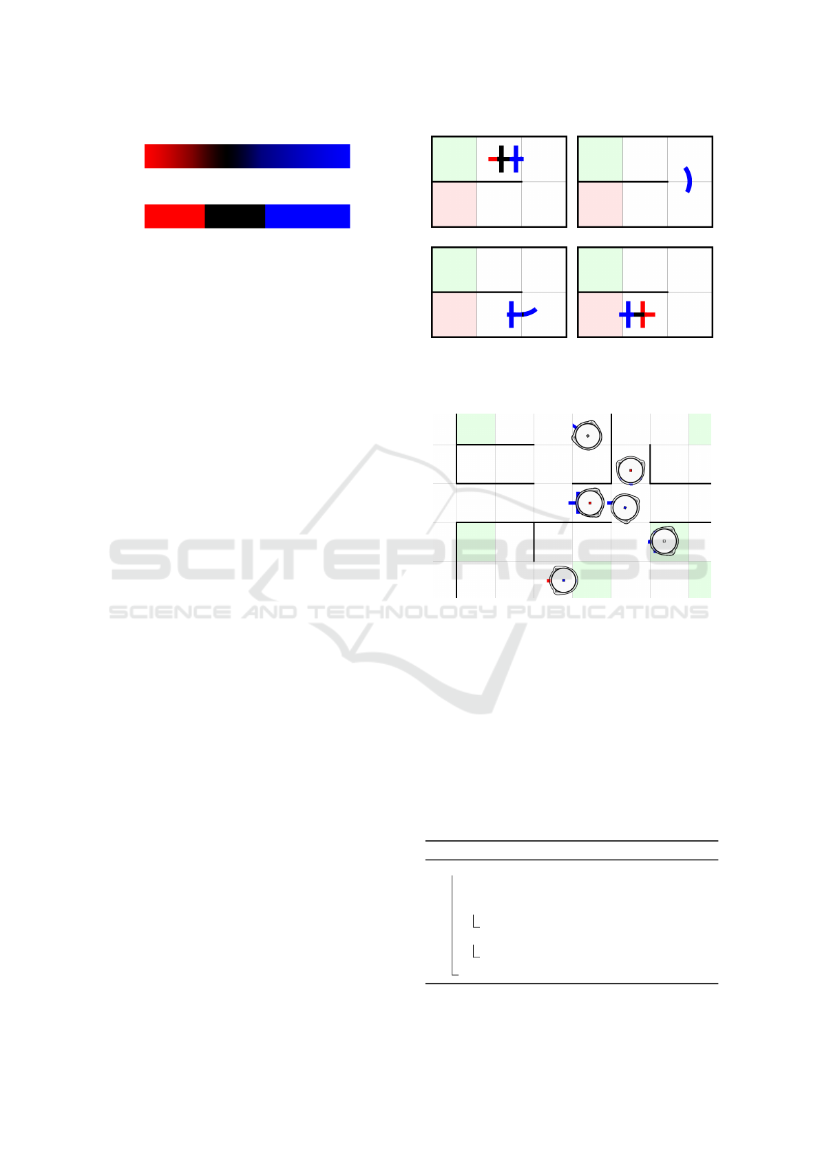
(a) Ideal gradient colored path
(b) Path segment divided into colored parts
Figure 9: Two versions of colored path segments.
would gradually change along the line’s length. For
example, from blue color at the front to red color at
the end, as shown in Figure 9(a). The robot, moving
on the following line, would continually read the line
color underneath its optical color sensor and gradually
change its movement speed. The speed would be in-
creased towards the red color and decreased towards
the blue color, forcing the robot to stay in the middle
of the path segment.
However, this ideal path segment representation
and agent behavior are not achievable due to the
Ozobot’s limitations. Ozobot cannot read the exact
values of color channels but instead recognizes eight
different colors. Therefore, a color gradient could
not be fully exploited, and the path segment had to
be divided into a few colored parts, as shown in Fig-
ure 9(b).
6.3.2 Colored Paths
Another drawback is that Ozobot cannot read from its
optical sensors while executing a line following com-
mand. To solve this problem, artificial intersections
have been added to the paths to interrupt the line-
following command in order to perform color read-
ings. Each of the three colors corresponds to differ-
ent movement speed. The final version of the colored
paths is shown in Figure 10. Turns in paths are drawn
as curves to make the turning of the robots smooth.
If the agent has to stop at a specific position, the path
segment stops its animation at the position. In some
scenarios, the robot is required to make a U-turn. For
this functionality, a special Color Code supported by
the Ozobot is displayed on the screen. The robot can
read the code and perform the turn.
An illustration of Ozobots navigating on the path
segments is shown in Figure 11.
6.4 Reflexive Behavior
The reflexive behavior of the Ozobot agents is written
as an OzoBlockly program and loaded to all robots
in the swarm. The behavior needs to follow the path
segments, read line colors, and adapt the movement
(a) t = 2.5s (b) t = 4.5s
(c) t = 6.0s (d) t = 7.0s
Figure 10: Colored path segments displayed in the map af-
ter t seconds from the start of the execution.
Figure 11: Illustration of Ozobots following colored path
segments on a map.
speed accordingly. The program can be found in Al-
gorithm 2. The main loop runs until the program is
manually terminated. As shown on line 7 of the code,
the robot moves on the path segments between the ar-
tificial intersections until it loses the following line.
When an intersection or a line end is encountered, the
line-following speed is updated on line 2. Because the
Ozobot naturally wants to choose a random direction
at any intersection, line 4 makes it always go straight.
However, if the movement was interrupted and there
is no line under the robot, line 6 stops it from moving.
Algorithm 2: Ozobot behavior program.
1 while true do
2 set line-following speed:
getSpeedFromLineColor() mm/s;
3 if there is way straight then
4 pick direction: straight;
5 else
6 stop motors;
7 follow line to next intersection or line end;
Deployment of Multi-agent Pathfinding on a Swarm of Physical Robots Centralized Control via Reflex-based Behavior
35
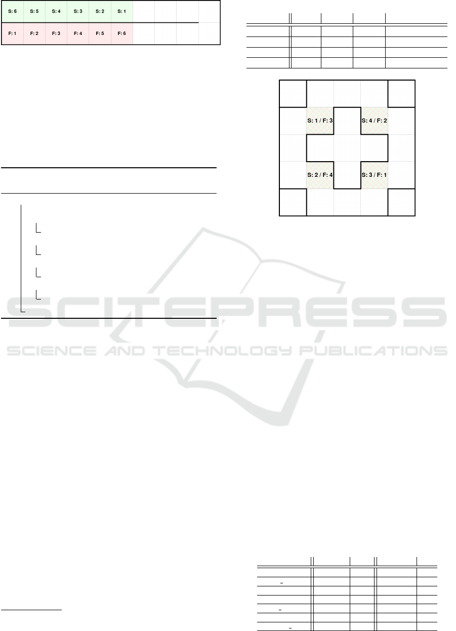
Figure 12: Experiment map: The snake.
The function getSpeedFromLineColor from line
2 is shown in Algorithm 3. First, the function reads
the surface color from the Ozobot’s optical color sen-
sor on line 2. On lines 3–10, the speed is chosen ac-
cording to the color, and on line 11, it is returned. The
speeds on each of the segments were chosen based on
the path segment animation speed.
Algorithm 3: Function reading line color and
returning speed.
1 Function getSpeedFromLineColor()
2 color ← get surface color;
3 if color = surface color red then
4 speed ← 37;
5 else if color = surface color black then
6 speed ← 30;
7 else if color = surface color blue then
8 speed ← 23;
9 else
10 speed ← 21;
11 return speed
7 EXPERIMENTAL EVALUATION
The prototype was experimentally evaluated on var-
ious scenarios where the focus was on the success
of execution. Each of the problem instances, repre-
sented by a map, was solved with both the move-to-
unoccupied variant (denoted m2u) and the standard
MAPF solver
5
.
7.1 Maps
For the experiments, four maps were used. Some of
the maps aim to test a specific feature, others provide
a balanced scenario for the execution. All of the maps
are listed in Table 3, and the previews of these maps
are shown in this section. For each map, its width,
height, and number of agents are provided in the table.
7.2 Results
Every plan was executed 32 times with the imple-
mented prototype. The execution is marked as suc-
5
For some maps, these two plans are identical, and only
one of them is experimented on.
Table 3: Maps created for experiments.
Map name Width Height Agents Image of the map
snake 10 2 6 In Figure 12
rotation 5 5 4 In Figure 13
swap 8 3 6 -
ordering 5 3 3 -
Figure 13: Experiment map: The rotation.
cessful if all Ozobots reach their goal positions. If at
least one loses the following line and does not reach
the goal, the execution is marked as a failure. The
plans are listed in Table 4, where also the results of
the experiments are summarized. During the testing,
two main reasons for execution failure were recorded.
The occurrence of these failures was counted and is
presented in the table of results.
The first reason for the failure of the execution is
robot collision. Most of the time, slight bumps did
not cause any significant issues. Sometimes, however,
robots collide in a way where they block each other
and cannot continue the plan execution. This problem
does not occur very often and is non-existent in the
move-to-unoccupied plans.
The second reason is an incorrect detection (ID)
of the sensors. This problem has occurred in various
situations. The most noticeable was incorrect execu-
tion of the Color Code, where the robot did not exe-
cute the U-turn command, or it executed it twice. In
both scenarios, the robot faced the wrong direction
and could not continue the plan execution. Some-
times, Ozobot even failed to detect an intersection
and update its speed. The occurrence of this mis-
Table 4: Results of the experiments.
Plan name
Success Fail Collision ID
snake 32 0 0 0
snake m2u 32 0 0 0
rotation 29 3 0 3
swap 30 2 0 2
swap m2u 30 2 1 1
ordering 30 2 1 1
ordering m2u 24 8 0 8
ROBOVIS 2020 - International Conference on Robotics, Computer Vision and Intelligent Systems
36

take resulted in execution failure if it happened before
a turn, where the robot needs to slow down. When
the robot was required to perform a wait action on a
turn, sometimes it oriented itself incorrectly. This re-
sulted in a situation where it could not follow the path
segment that reappeared underneath it. On rare occa-
sions, Ozobot was unable to follow the path correctly
after a turn.
7.3 Summary of Results
Overall, these experiments demonstrated the ability of
this deployment strategy to be used for the execution
of MAPF solutions that are even constructed on top
of the classical discrete MAPF abstraction. The sim-
ulation with physical robots also shown that this abil-
ity to perform the plan execution correctly is highly
dependent on the physical agents and their ability to
read and respond to the environment outputs. As for
the Ozobots, their main weakness is the variable accu-
racy of optical sensors with different light conditions.
A reflex-based active correction of desynchronization
showed to be successful in keeping the plan execu-
tion synchronized. Since the experiments were suc-
cessfully performed on such limited hardware, it indi-
cates that better results could be achieved with more
sophisticated robotic agents.
8 CONCLUSION
This work has described a new strategy of deploying
discrete MAPF solutions on a swarm of reflex-based
physical robots. A swarm of Ozobot Evo robots has
been used for the prototype application. The proto-
type showed that using the reflexive behavior of the
agents can be used to implement active correction of
desynchronization that can occur during the plan exe-
cution. It has also been confirmed that discrete MAPF
solutions can be deployed on reflex-based robots that
move continuously using environment outputs.
Experiments performed on the system identified
several problems that need to be overcome to execute
the plan execution successfully. Most of them are de-
pendent on the capabilities of robots being used. Us-
ing reflex control of robots through path animation on
the surface of the screen makes this strategy capable
of functionality extensions.
This deployment strategy can also be used for
MAPF demonstrations in research or academics.
Some real-world applications like intelligent evacu-
ation systems and indoor transporter navigation in
warehouses also could benefit from this approach.
ACKNOWLEDGEMENTS
This work has been supported by GA
ˇ
CR - the Czech
Science Foundation, grant registration number 19-
17966S.
REFERENCES
Andreychuk, A., Yakovlev, K. S., Atzmon, D., and Stern, R.
(2019). Multi-agent pathfinding with continuous time.
In Proceedings of the 28th International Joint Confer-
ence on Artificial Intelligence, pages 39–45. ijcai.org.
Atzmon, D., Stern, R., Felner, A., Wagner, G.,
Bart
´
ak, R., and Zhou, N. (2018). Robust multi-agent
path finding. In Proceedings of the 11th Interna-
tional Symposium on Combinatorial Search, pages 2–
9. AAAI Press.
Bart
´
ak, R., Svancara, J., Skopkov
´
a, V., and Nohejl, D.
(2018). Multi-agent path finding on real robots:
First experience with ozobots. In Proceedings of IB-
ERAMIA, volume 11238 of Lecture Notes in Com-
puter Science, pages 290–301. Springer.
Basile, F., Chiacchio, P., and Coppola, J. (2012). A hy-
brid model of complex automated warehouse systems
- part I: modeling and simulation. IEEE Trans. Au-
tomation Science and Engineering, 9(4):640–653.
Botea, A., Bouzy, B., Buro, M., Bauckhage, C., and Nau,
D. S. (2013). Pathfinding in games. In Artificial and
Computational Intelligence in Games, volume 6 of
Dagstuhl Follow-Ups, pages 21–31. Schloss Dagstuhl
- Leibniz-Zentrum f
¨
ur Informatik.
Boyarski, E., Felner, A., Stern, R., Sharon, G., Betzalel,
O., Tolpin, D., and Shimony, S. E. (2015). ICBS: the
improved conflict-based search algorithm for multi-
agent pathfinding. In Proceedings of the 8th Annual
Symposium on Combinatorial Search, pages 223–225.
AAAI Press.
de Wilde, B., ter Mors, A., and Witteveen, C. (2014). Push
and rotate: a complete multi-agent pathfinding al-
gorithm. Journal of Artificial Intelligence Research,
51:443–492.
Dresner, K. and Stone, P. (2008). A multiagent approach to
autonomous intersection management. JAIR, 31:591–
656.
Erdem, E., Kisa, D. G.,
¨
Oztok, U., and Sch
¨
uller, P. (2013).
A general formal framework for pathfinding problems
with multiple agents. In Proceedings of the 27th AAAI
Conference on Artificial Intelligence. AAAI Press.
Evollve, Inc. (2020a). Image of ozobot evo. https://ozobot.
com/. Last accessed on Mar 25, 2020.
Evollve, Inc. (2020b). Ozobot. https://ozobot.com/. Last
accessed on Mar 25, 2020.
Evollve, Inc. (2020c). Ozobot sensor layout im-
ages. https://files.ozobot.com/classroom/
2019-Educator-Guide.pdf. Last accessed on Mar 25,
2020.
Deployment of Multi-agent Pathfinding on a Swarm of Physical Robots Centralized Control via Reflex-based Behavior
37

Ivanov
´
a, M. and Surynek, P. (2013). Adversarial coopera-
tive path-finding: A first view. In Late-Breaking De-
velopments in the Field of Artificial Intelligence, vol-
ume WS-13-17 of AAAI Workshops. AAAI.
Jansen, M. R. and Sturtevant, N. R. (2008). A new ap-
proach to cooperative pathfinding. In 7th Interna-
tional Joint Conference on Autonomous Agents and
Multiagent Systems, pages 1401–1404. IFAAMAS.
Kim, D.-G., Hirayama, K., and Park, G.-K. (2014). Col-
lision avoidance in multiple-ship situations by dis-
tributed local search. Journal of Advanced Com-
putational Intelligence and Intelligent Informatics,
18:839–848.
Kornhauser, D., Miller, G. L., and Spirakis, P. G. (1984).
Coordinating pebble motion on graphs, the diameter
of permutation groups, and applications. In FOCS,
1984, pages 241–250.
Li, J., Surynek, P., Felner, A., Ma, H., Kumar, T. K. S., and
Koenig, S. (2019). Multi-agent path finding for large
agents. In The 33rd AAAI Conference on Artificial
Intelligence, pages 7627–7634. AAAI Press.
Luna, R. and Bekris, K. E. (2011a). Push and swap: Fast
cooperative path-finding with completeness guaran-
tees. In Proceedings of IJCAI 2011, pages 294–300.
IJCAI/AAAI.
Luna, R. and Bekris, K. E. (2011b). Push and swap: Fast co-
operative path-finding with completeness guarantees.
In IJCAI, pages 294–300.
Ratner, D. and Warmuth, M. K. (1986). Finding a shortest
solution for the N x N extension of the 15-puzzle is
intractable. In AAAI, pages 168–172.
Ryan, M. R. K. (2008). Exploiting subgraph structure in
multi-robot path planning. J. Artif. Intell. Res. (JAIR),
31:497–542.
Sharon, G., Stern, R., Felner, A., and Sturtevant, N. R.
(2015). Conflict-based search for optimal multi-agent
pathfinding. Artificial Intelligence, 219:40–66.
Sharon, G., Stern, R., Goldenberg, M., and Felner, A.
(2013). The increasing cost tree search for opti-
mal multi-agent pathfinding. Artificial Intelligence,
195:470–495.
Silver, D. (2005). Cooperative pathfinding. In Proceedings
of the First Artificial Intelligence and Interactive Dig-
ital Entertainment Conference, volume 1, pages 117–
122. AAAI Press.
Surynek, P. (2009). A novel approach to path planning for
multiple robots in bi-connected graphs. In IEEE In-
ternational Conference on Robotics and Automation,
pages 3613–3619. IEEE.
Surynek, P. (2012). Towards optimal cooperative path plan-
ning in hard setups through satisfiability solving. In
Proceedings of PRICAI 2012, volume 7458 of Lecture
Notes in Computer Science, pages 564–576. Springer.
Surynek, P. (2017). Time-expanded graph-based proposi-
tional encodings for makespan-optimal solving of co-
operative path finding problems. Ann. Math. Artif. In-
tell., 81(3-4):329–375.
Surynek, P. (2019). Unifying search-based and
compilation-based approaches to multi-agent path
finding through satisfiability modulo theories. In Pro-
ceedings of the 28th International Joint Conference
on Artificial Intelligence, pages 1177–1183. ijcai.org.
Wang, K. and Botea, A. (2011). MAPP: a scalable multi-
agent path planning algorithm with tractability and
completeness guarantees. JAIR, 42:55–90.
Wilson, R. M. (1974). Graph puzzles, homotopy, and the
alternating group. Journal of Combinatorial Theory,
Series B, 16(1):86 – 96.
Yu, J. and LaValle, S. M. (2013). Planning optimal paths
for multiple robots on graphs. In IEEE International
Conference on Robotics and Automation, pages 3612–
3617. IEEE.
Zhou, D. and Schwager, M. (2015). Virtual rigid bodies
for coordinated agile maneuvering of teams of micro
aerial vehicles. In ICRA 2015, pages 1737–1742.
ROBOVIS 2020 - International Conference on Robotics, Computer Vision and Intelligent Systems
38
