
Behavioural Modelling of Digital Circuits in System Verilog using
Grammatical Evolution
Conor Ryan
1 a
, Michael Kwaku Tetteh
1 b
and Douglas Mota Dias
1,2 c
1
CSIS, University of Limerick, Limerick, Ireland
2
UERJ, Rio de Janeiro State University, Brazil
Keywords:
Grammatical Evolution, Digital Circuit Design, Evolvable Hardware, Hardware Description Languages
(HDL), Lexicase Selection.
Abstract:
Digital circuit design is an immensely complex and time consuming task that has been aided greatly by the
use of Hardware Description Languages and powerful digital circuit simulators that permit a designer to
program at a much higher level of abstraction, similar to how software programmers now rarely use Assembly
Language, and also to test their circuits before committing them to hardware. We introduce Automatic Design
of Digital Circuits (ADDC), a system comprised of Grammatical Evolution (GE), System Verilog, a high level
Hardware Description Language (HDL) and Icarus, a powerful, but freely available, digital circuit simulator.
ADDC operates at a much higher level than previous digital circuit evolution due to the fact that System
Verilog supports behavioural modelling through the use of high level constructs such as If-Then-Else, Case
and Always procedural blocks. Not only are HDLs very expressive, but they are also far more understandable
than circuit diagrams, so solutions produced by ADDC are quite interpretable by humans. ADDC is applied to
three benchmark problems from the Digital Circuit Literature. We show that ADDC is successful on all three
benchmarks and further demonstrate how the integration of simple knowledge, e.g. the separation of input and
output wires, is feasible through the grammars, and can have a major impact on overall performance.
1 INTRODUCTION
Designing circuits for digital integrated circuits (ICs)
is a highly skilled and demanding job and a slow and
expensive process (Rabey et al., 2003), with minor er-
rors in design costing millions of dollars to fix. To
make the task tractable, specialized Hardware De-
scription Languages (HDLs) are used to design the
circuits, which are heavily tested in simulators before
being committed to hardware.
This paper introduces ADDC, an automated dig-
ital circuit design tool that uses a combination of
GE, Verilog and Icarus (a digital circuit simulator) to
evolve programs for a number of classic benchmarks.
While there has been some related work, described in
Section 2, most of it operates at a lower level of ab-
straction, e.g. at the gate level, while the use of HDLs
is akin to using a high level language such as C++ in-
stead of Assembly Language.
a
https://orcid.org/0000-0002-7002-5815
b
https://orcid.org/0000-0002-4351-0962
c
https://orcid.org/0000-0002-1783-6352
This work investigates the applicability of GE to
circuit design and how best to set it up. We use infor-
mation known about the problems to obtain a gram-
mar variant each, for all three problems, while ob-
serving their respective effect on evolutionary perfor-
mance. Experimentally, we show how best to set up
the system, most notably in terms of grammar design.
In Subsection 2.2 we describe related work;
Section 3 details the problems tackled, parameters
and grammars used for the experments; Section 4
presents and discusses the results obtained from the
experiments conducted; and Section 5 summarizes
the results and future works arising from this work.
2 BACKGROUND
Digital circuit design can be looked upon as operat-
ing at different levels. The lowest level, gate level,
deals with logic gates, and specifies exactly how a cir-
cuit should be created, while functional level, some-
times referred to as Register Transfer Level (RTL),
operates at a slightly higher level, consisting of pro-
28
Ryan, C., Tetteh, M. and Dias, D.
Behavioural Modelling of Digital Circuits in System Verilog using Grammatical Evolution.
DOI: 10.5220/0010066600280039
In Proceedings of the 12th International Joint Conference on Computational Intelligence (IJCCI 2020), pages 28-39
ISBN: 978-989-758-475-6
Copyright
c
2020 by SCITEPRESS – Science and Technology Publications, Lda. All rights reserved
grams made up of instructions that can directly be
translated into gate level. The highest level is be-
havioural; this consists of programs written in Hard-
ware Description Languages (HDLs), such as Ver-
ilog/System Verilog and VHDL, although many more
exist. These programs mimic the desired functionality
of the hardware, although, perhaps surprisingly, not
all behavioural programs are synthesizable, meaning
that they cannot be realized in hardware.
Most modern complex digital circuits are con-
structed using some form of HDL, and are then sub-
ject to numerous simulation and testing steps to en-
sure that not only is the circuit functionally correct,
but also that it is indeed synthesizable. There are
many powerful tools, such as Quartus (Intel/Altera)
and Vivado (Xilinx), that are used by design experts to
perform various tests on their programs before com-
mitting them to hardware.
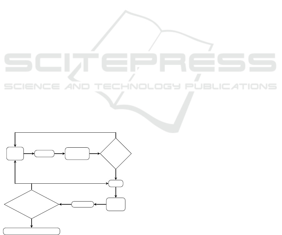
Computer Aided Design (CAD) for circuits em-
ploys these sorts of tools in an iterative way, as
shown in Figure 1, where designers repeatedly per-
form functional simulations to ensure that their cir-
cuit works as intended, before moving to the synthe-
sis phase, in which they ensure that the circuit is fully
synthesizable. The reasons why a circuit may not be
synthesizable vary from timing issues (components
may simply be too far from each other and thus intro-
duce some unexpected delays) to fitting issues (it may
not be possible to create this particular circuit given
the real estate available), amongst others.
Key to any digital circuit design is the creation of
a testbench. A testbench is analogous to a regression
test in software programming, as it essentially con-
tains a set of test cases, although testbenches typically
contain extra code to actually run the circuit under test
on the various test cases.
Design
Entry
Synthesis
Functional
Simulation
Design Correct?
NO
YES
Fitting
Timing
Analysis
Simulation
Timing require-
ments met?
NO
Programming & Configuration
YES
Figure 1: The standard CAD flow for digital circuit design.
2.1 Evolvable Hardware
Evolvable Hardware (EHW) is a field that deals with
the application of evolutionary algorithms (EAs) to
electronic circuit design. It is comprised of two ma-
jor areas based on its application—adaptive hard-
ware (a.k.a. Darwin Machine (de Garis, 1993)) and
circuit synthesis (Yao and Higuchi, 1999). With
adaptive hardware, hardware is equipped to au-
tonomously adapt or reconfigure its architecture as
it interacts with its environment, while, with circuit
synthesis, behavioural requirements are known up-
front. The circuit is evolved and tested using sim-
ulators similar to those noted above, before being
committed to hardware; this is referred to as extrin-
sic evolution in EHW (de Garis, 1994). Other modes
of evolution are intrinsic and mixtrinsic. In intrinsic
evolution, candidate circuits are directly simulated
on a target hardware such as Field Programmable
Gate Arrays (FPGAs) (Thompson, 1997), while
mixtrinsic evolution is a combination of both in-
trinsic and extrinsic evolution for simulating the
evolved circuits—thus a population is divided in
two, with each half evaluated with one of the evalu-
ation modes, but not on both (Stoica et al., 2000).
2.2 Related Work
EAs have been applied to circuit design, both in the
analog and digital circuits design domains. How-
ever, as the focus of this work is in the digital circuit
domain, we restrict our review to such circuits. Most
studies carried out in EHW applied to circuit syn-
thesis have operated at the gate and functional level
evolution. For example, Cartesian GP (CGP) (Miller
and Thomson, 2000), a GP variant, has been used
extensively to evolve digital circuits at both gate
and functional level. CGP uses directed acyclic
graphs as the program encoding structure instead of
trees (Miller and Thomson, 2000). A CGP genotype
consist of different kinds of genes: a function gene
which holds an address to a function in a lookup ta-
ble that a node in the graph must perform, connec-
tion genes that encode addresses of where a node can
take its inputs from, which is usually in a feedfor-
ward manner (Miller and Thomson, 2000), and out-
put genes which hold addresses of nodes where out-
puts of the program can be retrieved. This represen-
tation makes CGP ideal for low level simulation, and
usually the output form of the final circuit design’s
phenotype is obtained or specified in boolean logic
form. At the gate level, CGP has been applied suc-
cessfully in evolving numerous digital circuits such
as seven segment display, adders and multipliers of
varying input sizes (Sekanina et al., 2011).
Behavioural Modelling of Digital Circuits in System Verilog using Grammatical Evolution
29

GE has also been used to evolve circuits such
as one-bit adder, d-latch at the gate level (Cullen,
2008) using Verilog. However, gate-level evolution
is that it is less likely to scale to highly complex cir-
cuits from scratch (Vassilev and Miller, 2000). In re-
sponse to issues of scalability inherent in gate level
evolution, Murakawa et al. proposed functional level
evolution, which uses higher level functions such as
multiplexers, adders, subtractors instead of primitive
gates (Murakawa et al., 1996) to help reduce the
search space. Similarly, Vassilev and Miller evolved
a 3-bit multiplier using only binary multipexers (Vas-
silev and Miller, 2000). 9- and 25-Median approx-
imate circuits have also been designed at the func-
tional (Vasicek and Sekanina, 2015). We address the
scalability concern by performing circuit evolution at
a more abstract level —behavioural modelling, where
focus is placed on describing the behaviour of the cir-
cuit.
The Production Genetic Algorithm (PGA), is a
GA augmented with a rewriting system which uses
a grammar to design digital circuits (Mizoguchi et al.,
1994). The chromosome of an individual dictates the
production rule to be used during the mapping pro-
cess. Using Structured Function Description Lan-
guage (SFL) as the HDL, PGA was applied to design
a circuit for an ant to follow the John Muir Trail.
2.3 Higher Abstraction Levels
Higher abstraction levels (e.g RTL) are much more
capable of evolving or finding solutions to complex
circuits quicker but do not necessary guarantee more
optimized designs when synthesized to lower levels
(gate or transistor level) which is the normal pro-
cess prior to the actual fabrication of any digital cir-
cuit (Gajda and Sekanina, 2007). Karpuzcu evolved a
1–bit full adder using an RTL grammar (Karpuzcu,
2005). Using a population size of 200, a termina-
tion criterion of a 100,000 fitness evaluations and 35
experimental runs found just two optimal solutions.
These runs took 50,369 and 19,772 fitness evaluations
respectively. We evolved the 1–bit full adder using the
same grammar in (Karpuzcu, 2005), same population
size (200) but opted for 200 generations as the termi-
nation criterion (thus 40,000 maximum evaluations).
We obtained 8 optimal solutions out of 30 runs after
23 generations on average(thus 4,600 fitness evalua-
tions). However, we do not include these results in
this paper as 1–bit full adder is trivial (increasing the
population size resulted in more successful runs) and
the grammar design did not exploit System Verilog’s
behavioural constructs enough.
Cullen, on the other hand, specified the grammar
at the gate level (Cullen, 2008). As the maximum
number of gates and wires needed per circuit design
cannot be determined due to nature of genetic algo-
rithms, these variables cannot be added to the gram-
mar prior to the experimental runs. As a result, a
post-processing technique for declaration and usage
of unique wires and gate instances was designed and
referred to as a DEFINE/USE pair (Cullen, 2008).
2.4 Grammatical Evolution
GE evolves programs in any arbitrary language us-
ing grammars, either Backus Naur Form (BNF) or At-
tribute Grammars (AG), and has been applied to many
domains such as bio-informatics, engineering and ar-
chitecture (Ryan et al., 2018). Digital circuit design
hasn’t received much attention from GE and, as noted
above, most previous EC work was at the gate level,
but the use of HDLs and the good availability of pow-
erful simulators suggests that it could be an ideal tar-
get.
GE operates by using a mapper that takes a geno-
type and a valid context grammar defined for a prob-
lem as inputs. The genotype consists of a sequence
of codons; usually each codon is an integer equiva-
lent of an 8–bit binary string decoded from a binary
string genome. Each rule begins with a non-terminal
and has a number of productions which expand into
other non-terminals or terminals. The modulo rule
is usually used for production rule selection (O’Neill
and Ryan, 2001). A valid phenotype is obtained if
all non-terminals have been fully expanded to termi-
nals, in which case a syntactically correct program or
program fragment in the target language has been de-
rived.
3 EXPERIMENTAL DESIGN
The main driver for the design of digital circuits in
this work is GE, with Icarus Verilog (Williams and
Baxter, 2002). We use LibGE, an open source C++
Table 1: Experimental Run Parameters.
Parameter Type Parameter Value
Initialization Sensible Initialization
No of generations 200
Mutation rate 0.01
Crossover rate 0.8
Replacement rate 0.5
No of runs 30
Population 2,000
Selection Lexicase Parent Selection
ECTA 2020 - 12th International Conference on Evolutionary Computation Theory and Applications
30
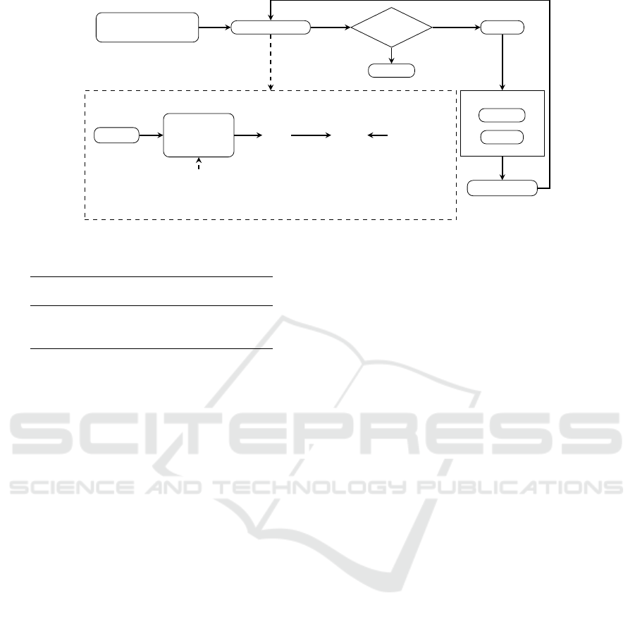
Initialization
(Initial Population)
Fitness Evaluation
Fitness Evaluation Process
Genotype
Genotype to
Phenotype
Mapping
%
Grammar.bn f
%
Circuit
i
.sv
Icarus
Verilog
(Simulator)
%
Testbench.sv
Terminate?
Terminate
YES
NO
Selection
Reproduction
Crossover
Mutation
New Population
Figure 2: GE circuit design process.
Table 2: Number of Testcases Used for each problem.
Problem
Number of
Testcases
11-Multiplexer 2,048
Seven Segment Display 16
Hamming Code (7,4) Decoder
128
implementation of Grammatical Evolution (Nico-
lau and Slattery, 2006) while Icarus Verilog is a
lightweight and open source simulator, used for sim-
ulating the circuits. Thus, all circuits are evolved ex-
trinsically using Icarus Verilog and testbenches de-
signed based on the truth tables for all three problems
described below. These testbenches are used by the
simulator to simulate the evolved circuits to test for
their correctness. The fitness of a circuit is simply the
sum of all the testcases successfully passed.
We use a population size of 2,000. The par-
ent selection technique employed is Lexicase selec-
tion (Spector, 2012). Lexicase selection selects indi-
viduals as parents depending on how well they per-
form on a randomly shuffled set of testcases, with
every selection requiring reshuffling of the testcases.
This increases the probability of choosing individuals
which, although might be relatively poor performers
overall, solve cases that much of the rest of the pop-
ulation do not. The circuit design process is captured
in Figure 2 , the parameters for the experiments are
detailed in Table 1 and number of testcases used is
shown in Table 2.
3.1 Differences between ADDC and
Existing Work
The key difference between the work presented in this
paper, ADDC, and existing work is the language used
to represent the circuits. Virtually all other work, in-
cluding those that employ HDLs, operate at the gate
level. ADDC operates at a higher level and thus has
access to the feature rich language of Verilog. For ex-
ample, common high level programming constructs
such as Always, If, Case, Boolean operators and nu-
meric constants are all standard in Verilog, but are not
trivial to code at the gate level. Thus, for complex
circuit designs, behavioural level modelling is prefer-
able (Bryan Mealy, 2018) and generated circuits are
intrepretable and maintainable by humans.
Furthermore, as demonstrated in Section 4, the
use of a grammar permits us to impose simple con-
straints on the search space that dramatically improve
the performance of the system. In this paper, we re-
strict these constraints to simple, commonsense, such
as separating the input and output wires.
3.2 Problems
Our three problems and associated grammars are de-
scribed below.
3.2.1 Multiplexer
A Multiplexer circuit switches data lines through a
single line using address or select lines. The multi-
plexer problem has been addressed using GP (Kruse
et al., 2013) and a classifer system (Fredivianus et al.,
2010). The Multiplexer Grammar A in Figure 3 uses
bitwise-and, bitwise-or, logical negation and ternary
operator as the function set. The Multiplexer Gram-
mar B in Figure 4 uses the ternary operator (a short-
ened form of if-else construct as the only functional
construct, which we speculate to be adequate in solv-
ing the multiplexer problem. In both grammars, the
data bits are distinguished from the address bits. This
sort of constraint is straightforward to impose with
GE, as it is simply a matter of modifying the gram-
mar slightly (specifically, the <expr> non-terminal),
while in standard GP, this would be a more complex
exercise as it is essentially introducing a new type,
Behavioural Modelling of Digital Circuits in System Verilog using Grammatical Evolution
31

hdesign-modulei ::= hbegin-moduleihnextlineihcode-blocki
hend-moduleihnextlinei
hcode-blocki ::= halwaysihstatementi
halwaysi ::= "always@(*)"hnextlinei
hstatementi ::= houtputi=hexpri;hnextlinei
hexpri ::=
hexpri&hexpri
|
hexpri"|"hexpri
| !
hexpri
|
haddress-biti?hexpri":"hexpri
| hdata-biti
houtputi ::= out
haddress-biti ::= a0 | a1 | a2
hdata-biti ::= d0 | d1 | d2 | d3 | d4 | d5 | d6 | d7
hnextlinei ::= "\n"
hbegin-modulei ::= module "mux(output logic out, input
logic a0, a1, a2, d0, d1, d2, d3,
d4, d5, d6, d7);"
hend-modulei ::= end-module
Figure 3: Multiplexer Grammar Version A; this grammar
variant separates the address bits from the data bits and Uses
the bitwise and (&), |, ternary operator ( if −else), bitwise
or (|) and logical negation (!) operators in the grammar.
hdesign-modulei ::= hbegin-moduleihnextlineihcode-blocki
hnextlineihend-modulei
hcode-blocki ::= halwaysihstatementi
halwaysi ::= always@(*)hnextlinei
hstatementi ::= houtputi"="hexpri;hnextlinei
hexpri ::=
haddress-biti?hexpri":"hexpri
| hdata-biti
houtputi ::= out
haddress-biti ::= a0 | a1 | a2
hdata-biti ::= d0 | d1 | d2 | d3 | d4 | d5 | d6 | d7
hnextlinei ::= "\n"
hbegin-modulei ::= module "mux(output logic out, input
logic a0, a1, a2, d0, d1, d2, d3,
d4, d5, d6, d7);"
hend-modulei ::= endmodule
Figure 4: Multiplexer Grammar B: The Grammar uses
if −else construct as the only functional construct and sep-
arates the data and address bits.
which would complicate the task of satisfying the
closure principle for GP. The grammar also features
the always proceedural block, which behaves like a
loop by continously executing all statements within
its body, starting at time 0.
3.2.2 Seven Segment Display (SSD)
An SSD is an electronic device which consists of
seven segments or LEDs for displaying decimal num-
bers as well as characters (limited to decimal numbers
in this work). The device receives a 4-bit binary num-
ber (0000 −1001) referred to as binary coded decimal
(BCD) as input and in response uses a 7–bit number
(each bit corresponding an ON/OFF state of a seg-
hdesign-modulei ::= hbegin-moduleihnext-lineihcode-blocki
hnext-lineiendmodule
hcode-blocki ::= halwaysihstatementi
halwaysi ::= always@(bcd)hnext-linei
hstatementi ::= beginhnext-lineihswitch-caseihnext-lineiend
hswitch-casei ::= case(bcd)hnext-lineihcase-statementi
hnext-lineihdefault-caseihnext-lineiendcase
hcase-statementi ::= hbcd-valuei":"houtputi"="hseven-segmenti;
| hbcd-valuei":"houtputi"="hseven-segmenti;
hnext-lineihcase-statementi
hdefault-casei ::= default":"houtputi"="hseven-segmenti;
hbcd-valuei ::= 4'bhbitihbitihbitihbiti
hseven-segmenti ::= 7'bhbitihbitihbitihbitihbitihbitihbiti
hnext-linei ::= "\n"
houtputi ::= segment
hbiti ::= 0 | 1
hbegin-modulei ::= module "ssdisplay(output logic[6:0]
seg, input logic[3:0] bcd);"
Figure 5: SSD Grammar Version A: The data and address
bits grouped together in the terminal rule and uses the bit-
wise and (&), ternary operator ( if −else), but has its BCD
values separated from the seven segment values.
hdesign-modulei ::= hbegin-moduleihnext-lineihcode-blocki
hnext-lineiendmodule
hcode-blocki ::= halwaysihstatementi
halwaysi ::= always@(bcd)hnext-linei
hstatementi ::= beginhnext-lineihswitch-caseihnext-lineiend
hswitch-casei ::= case(bcd)hnext-lineihcase-statmenti
hnext-lineihdefault-caseihnext-lineiendcase
hcase-statementi ::= hterminali:houtputi"="hterminali;
| hterminali":"houtputi=hterminali;
hnext-lineihcase-statementi
hdefault-casei ::= default":"houtputi"="hterminali;
hnextlinei ::= "\n"
houtputi ::= segment
hbcd-valuei ::= 4'b0000 | 4'b0001 | 4'b0010 | 4'b0011
| 4'b0100 | 4'b0101 | 4'b0110
| 4'b0111 | 4'b1000 | 4'b1001
hseven-segmenti ::= 7'b1111110 | 7'b0110000 | 7'b1101101
| 7'b1111001 | 7'b0110011 | 7'b1011011
| 7'b1011111 | 7'b1110000 | 7'b1111111
| 7'b1111011 | 7'b0000000
hbegin-modulei ::= module "ssdisplay(output logic[6:0]
seg, input logic[3:0] bcd);"
Figure 6: SSD Grammar Version B; this grammar is similar
to SSD Grammar Version A in Figure 5 but its BCD and
seven segment values are separated in the same they are in
SSD Gramamr Version A.
ment) to turn on the appropriate segments/LEDs in
displaying the digit. The two grammars designed for
the SSD problem both use the switch-case construct
as the only functional construct. In SSD Grammar A
and B in Figure 5 and Figure 6 respectively, using
ECTA 2020 - 12th International Conference on Evolutionary Computation Theory and Applications
32

a similar approach to the Multiplexer Grammar de-
sign, the BCD-values and seven-segments are distin-
guished from each other. To investigate the impact of
grammar design decisions/domain knowledge intro-
duced into grammars on evolutionary performance, in
Grammar A in Figure 5 the grammar is designed in
such a way that it constructs the binary numbers from
single bits (assuming the appropriate binary numbers
required by the problem are not known). This is
a non-trivial task, particularly as not all values are
needed. Given that there is a defined set of inputs
and outputs, we encode this information into gram-
mar variant B in Figure 6. Note that the individu-
als still need to build the case statement, which is a
variable length construct, in which each case can be
one of 110 possibilities, so this is not a trivial prob-
lem. SSD Grammar B in Figure 6 has all the BCD
and seven segment values explicitly defined and dis-
tinguished from each other making this grammar the
least difficult and should have the best success rate in
solving the SSD problem.
3.2.3 Hamming Code (7,4) Decoder
Hamming Codes belong to the category of error cor-
recting codes known as Linear Block Codes (Miller
et al., 2009). This category of codes have a minimum
distance of 3, meaning that they are capable of cor-
recting a single error and at most detecting two errors.
The Hamming Code (7,4) encodes a dataword by gen-
erating three parity check bits using the 4–bit data-
word. The 3 parity check bits and the 4–bit dataword
are combined to create a 7–bit binary string referred
to as the codeword. After transmission, the Hamming
Code (7,4) decoder retrieves the dataword from the
codeword by generating a 3–bit number referred to as
the syndrome. Each bit serves as a parity check for
4–bit codeword. Figure 13 and Figure 14 represents
the grammars designed to evolve the Hamming Code
(7,4) decoder. Both grammars feature a function to
generate the syndrome from the codeword received,
as well as an always block together with an if-else
construct that checks the generated syndrome for va-
lidity or corruption of the codeword. If the syndrome
is non-zero then the codeword has been corrupted dur-
ing transmission. To correct the codeword, the dec-
imal equivalence of the generated syndrome deter-
mines the bit position where an error is assumed to
have occured during transmission and as a result the
bit at the location is flipped. The production(s) for the
hexpri rule differentiates Hamming Code (7,4) De-
coder Grammar A from Grammar B as shown in Fig-
ure 13 and Figure 14 respectively in the APPENDIX.
The productions of the Hamming Code (7,4) Decoder
Grammar A are designed in such a way that evolution
has to find the expression that generates the correct
parity bit which forms part of the 3–bit syndrome.
However, from the problem statement of the Ham-
ming Code (7,4) Decoder, only 4–bits out of the 7–bit
codeword are required in deriving the expression that
generates each parity bit that make up the 3–bit syn-
drome used for checking the correctness of the re-
ceived dataword. As a result, we incorporate this in-
formation into the design of the production associated
with the hexpri rule of the Hamming Code (7,4) De-
coder Grammar B. This design decision ensures 4 bits
out of the 7–bit codeword are selected every time in
deriving the expression. We therefore speculate that
Hamming Code (7,4) Grammar B should exhibit bet-
ter chances of solving the Hamming Code (7,4) De-
coder problem than its Grammar B counterpart.
4 RESULTS AND DISCUSSION
In this section we present and discuss the results ob-
tained from the thirty experimental runs conducted
across each of the three problems examined. Fig-
ures 10−11 show the mean average and best fitnesses
across generations with error bars.
4.1 Successful Runs
We tabulated the success rate in order to visualize the
impact of grammar design on the frequency of find-
ing optimal solutions. Table 3 shows the success rate
of the 11–bit multiplexer, SSD and Hamming Code
(7,4) decoder, respectively, across all 30 experimen-
tal runs. Both Multiplexer Grammar A and Seven
Segment Display Grammar A were unable to obtain
any optimal solution within 200 generations with a
population of 2,000. To investigate this further, we
conducted another experiment using the Grammar A
versions of the SSD and the 11-bit multiplexer prob-
lems while increasing the population size from 2,000
to 3,000. Again, no optimal solutions were obtained
using the 11–bit Multiplexer Grammar A version, al-
though 4 optimal solutions out of the 30 runs were
obtained using the Seven Segement Grammar A ver-
sion. Thus, more fitness evaluations are required to
obtain optimal solutions if grammars are not con-
cise enough. The Grammar A variants for the multi-
plexer and SSD problems performed worse than their
B counterparts due to the absence of the common-
sense domain knowledge infused into the grammars.
Behavioural Modelling of Digital Circuits in System Verilog using Grammatical Evolution
33
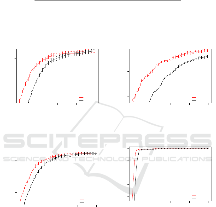
Table 3: Success Rate.
Problem Grammar Successful Runs (out of 30)
11–bit Multiplexer Grammar A 0
11–bit Multiplexer Grammar B 22
Seven Segment Display Grammar A 0
Seven Segment Display Grammar B 28
Hamming Code (7,4) Decoder Grammar A 22
Hamming Code (7,4) Decoder Grammar B 30
0 50 100 150 200
0.75 0.80 0.85
Generation
Fitness
Mean Best
Mean Avg
Figure 7: Mean Average / Mean Best for 11-bit Multiplexer
Grammar Version A with error bars. The address bits are
distinguished from data bits. Uses the bitwise and, ternary
operator (if-else), bitwise or and logical negation opera-
tors in the grammar.
0 50 100 150 200
0.4 0.5 0.6 0.7 0.8
Generation
Fitness
Mean Best
Mean Avg
Figure 9: Mean Average / Mean Best for Seven Segment
Display Grammar Version A with error bars. Has its BCD
values separated from the seven segment values. Also, it
contains the necessary building blocks for generating the
required BCD and seven segment values.
4.2 Grammar Choice
The use of domain knowledge in the derivation of
the 11-bit Multiplexer, SSD Grammar and Hamming
Code (7,4) Decoder variants had the intended influ-
ence in reducing the search space.
0 50 100 150 200
0.80 0.85 0.90 0.95
Generation
Fitness
Mean Best
Mean Avg
Figure 8: Mean Average / Mean Best for 11-bit Multiplexer
Grammar B Version with error bars. Uses if-else con-
struct as the only functional construct and has its data bits
distinguished from the address bits.
0 50 100 150 200
0.6 0.7 0.8 0.9 1.0
Generation
Fitness
Mean Best
Mean Avg
Figure 10: Mean Average / Mean Best for Seven Segment
Display Grammar Version B with error bars. It’s BCD and
seven segment values are separated. Also, all the required
BCD and seven-segment values were explicitly specified.
Recall that the Multiplexer Grammar A version
had other functions in addition to the ternary operator
which were not required, given that the ternary oper-
ator (if-else) is sufficient to model the behaviour of
the 11-bit multiplexer problem. From Figure 7 and
Figure 8, we observe that the Multipexer Grammar B
which uses the ternary operator as the only functional
construct outperformed Multiplexer Grammar A by a
significant margin. Therefore, the impact of gram-
ECTA 2020 - 12th International Conference on Evolutionary Computation Theory and Applications
34
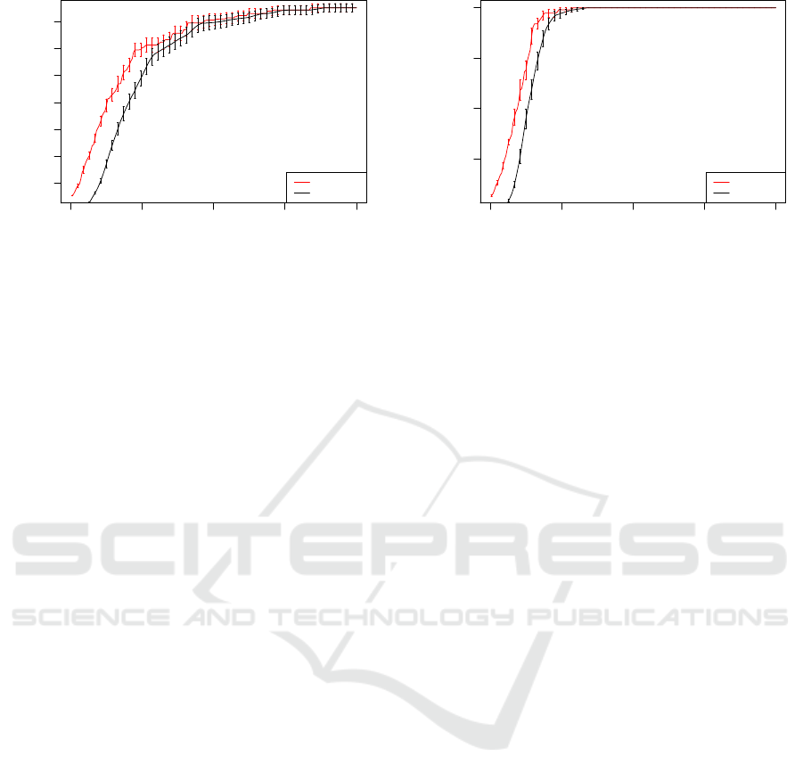
0 50 100 150 200
0.3 0.4 0.5 0.6 0.7 0.8 0.9
Generation
Fitness
Mean Best
Mean Avg
Figure 11: Mean Average/ Mean Best for Hamming Code
(7,4) Decoder Grammar A Version with error bars. The
hexpri is recursive by design and evolution has to derive
the correct expressions that generate the syndrome.
mar design, specifically the use of highly expressive
functions such as if-else, which we can do in this case
because we are evolving at the behavioural level.
The SSD Grammar A version had to construct the
BCD values and the 7 segment bits while the Gram-
mar B version had these defined within the grammar.
As speculated, from Figure 9 and Figure 10, the
Grammar B Version performed better than its Gram-
mar A counterpart. This is due to the fact that the
Grammar A version had an additional task of con-
structing the BCD and 7 segment binary numbers.
Also, from Table 3 Grammar A was unable to obtain
an optimal solution in any of the 30 runs conducted.
The only difference between the Hamming Code
(7,4) Decoder Grammar A and B is the hexpri rule.
In the case of the Grammar A, the productions of the
hexpri rule were designed in such a way that the re-
sulting expression can be of an arbitrary length; in
other words evolution has to figure out the right ex-
pression that generates the right parity bit. However,
from the description of the Hamming Code (7,4) De-
coder we know the resulting expression that generates
each bit of the 3-bit syndrome has to select only 4 bits
out of the 7–bit codeword. As a result we limit the
production of the hexpri rule to select 4 bits out of 7-
bit codeword, making Grammar B capable of solving
the Hamming Code (7,4) Decoder better and quicker
comparatively. From Figure 11 and Figure 12, we
observe that Hamming Code (7,4) Decoder Gram-
mar B outperforms it’s Grammar A counterpart. This
shows the impact a simple domain knowledge con-
straint can have on evolutionary performance with re-
gards to grammar design. This further supports our
claim that the use of grammars facilitates the intro-
duction of simple and generic, but useful constraints
on the search space.
An optimal solution for each successful grammar
0 50 100 150 200
0.4 0.6 0.8 1.0
Generation
Fitness
Mean Best
Mean Avg
Figure 12: Mean Average/ Mean Best for Hamming Code
(7,4) Decoder Grammar B Version with error bars. The
hexpri for this Grammar Version is not recursive but instead
limited in length which we know from the problem descrip-
tion.
have been shown in Listings 1– 4 in the APPENDIX.
The Multiplexer Grammar B solutions vary in length
due to the nesting nature of the if-else construct.
Similarly, the number of case-statements varies
across solutions obtained using Seven Segement Dis-
play Grammar B, out of which some are redundant;
since System Verilog permits duplicate cases but eval-
uates them based on preceedence. Hamming Code
(7,4) Decoder Grammar A solutions are identical ex-
cept the arrangment of the bits in the expressions
that generate the syndromes vary but are of no rele-
vance. However, solutions obtained using the Ham-
ming Code (7,4) Decoder Grammar B differ in the
length of the expressions that generate the syndromes
due to the recursiveness of the hexpri rule. These ex-
pressions contain bitwise operations that are redun-
dant, for example cw
1
&cw
1
= cw
1
5 CONCLUSION AND FUTURE
WORK
We have presented ADDC, the Automated Design of
Digital Circuits, which uses a combination of GE,
Verilog and Icarus to evolve digital circuits. We
have tested it on three difficult benchmarks and have
demonstrated how grammar can be leveraged to dra-
matically reduce the search space by separating out
clearly distinct wires, i.e. input and output and the
inclusion of relevant functions such as the ternary op-
erator (if-else) in the case of the Multiplexer Gram-
mar B version.
These experiments have also demonstrated the im-
pact of high-evel structures, such as If, always pro-
ceedural blocks and case on evolving circuits. Be-
Behavioural Modelling of Digital Circuits in System Verilog using Grammatical Evolution
35

cause these are so expressive, they can replace many
gates that would otherwise have to be evolved, and
instead permit evolution to focus on higher level be-
haviours. In all cases where we were able to test the
impact of these, the best performance came from set-
ups that used both of the features, i.e. separating the
input and output space and the use of high level struc-
tures.
These findings show a roadmap for tackling much
more complex tasks, specifically, the ways in which
the grammars are designed and the use of Lexicase
Selection to target poorly covered parts of the solu-
tion space. Additionally, results obtained based on the
grammar design choices suggest that the use of Lay-
ered Learning or Attribute grammars may be better
suited for tougher circuit problems.
The problems tackled in this work are interest-
ing as they are of relevance in real-world applica-
tions. Moving forward, more difficult problems such
as 70–bit and 135–bit Multiplexers, Hamming Code
(127, 120) Decoder and multipliers of varying inputs
will be looked at. Though the problems tackled in
this work are not very difficult, we demonstrated that
grammar design can impose another level of difficulty
on problems; as a result no optimal solutions were
found for the Grammar A versions of the SSD and
Multiplexer problems. In this paper we also assume
to be evolving circuits from scratch which may not
be the case in industrial applications. Future works
will also target using IP blocks as modules to evolve
more complex circuits; adding them to our system
will be trivial, as it will simply involve adding them
to the grammar. Furthermore, all three problems were
treated as single objective problems, that is, func-
tionality. Future work will consider their optimiza-
tion when synthesized to a lower level such as the
gate level, probably using some multi-objective fit-
ness measures. Also relevant is the need to adopt
techniques to help decompose problems into subprob-
lems in an attempt to reduce the search space, particu-
larly for problems of high complexity, as is often done
in digital circuit design. Furthermore, the incorpora-
tion of semantic information into GE will be key in
ensuring only syntactically and semantically valid in-
dividuals are evaluated, as long simulation time is a
difficult bottleneck to address.
Crucially, because the system we have assembled
uses a full Verilog simulator that employs test benches
to test the circuits, there is a clear path to extend
ADDC to sequential circuits, that is, logic circuits
that are time dependent and require a clock to oper-
ate. This opens up the possibility of employing highly
powerful building blocks such as flip-flops and coun-
ters.
ACKNOWLEDGMENTS
The authors are supported by Research Grant
16/IA/4605 from the Science Foundation Ireland and
by Lero, the Irish Software Engineering Research
Centre. The third author is partially financed by
the Coordenac¸
˜
ao de Aperfeic¸oamento de Pessoal de
N
´
ıvel Superior - Brasil (CAPES) - Finance Code 001.
REFERENCES
Bryan Mealy, F. T. (2018). Free Range VHDL.
Cullen, J. (2008). Evolving Digital Circuits in an Indus-
try Standard Hardware Description Language. In Li,
X., Kirley, M., Zhang, M., Green, D., Ciesielski, V.,
Abbass, H., Michalewicz, Z., Hendtlass, T., Deb, K.,
Tan, K. C., Branke, J., and Shi, Y., editors, Simulated
Evolution and Learning, pages 514–523, Berlin, Hei-
delberg. Springer Berlin Heidelberg.
de Garis, H. (1993). Evolvable Hardware Genetic Program-
ming of a Darwin Machine. In Albrecht, R. F., Reeves,
C. R., and Steele, N. C., editors, Artificial Neural
Nets and Genetic Algorithms, pages 441–449, Vienna.
Springer Vienna.
de Garis, H. (1994). An artificial brain ATR’s CAM-Brain
Project aims to build/evolve an artificial brain with a
million neural net modules inside a trillion cell Cellu-
lar Automata Machine. New Generation Computing,
12(2):215–221.
Fredivianus, N., Prothmann, H., and Schmeck, H. (2010).
Xcs revisited: A novel discovery component for the
extended classifier system. In Deb, K., Bhattacharya,
A., Chakraborti, N., Chakroborty, P., Das, S., Dutta,
J., Gupta, S. K., Jain, A., Aggarwal, V., Branke, J.,
Louis, S. J., and Tan, K. C., editors, Simulated Evo-
lution and Learning, pages 289–298, Berlin, Heidel-
berg. Springer Berlin Heidelberg.
Gajda, Z. and Sekanina, L. (2007). Reducing the Number of
Transistors in Digital Circuits Using Gate-level Evo-
lutionary Design. In Proceedings of the 9th Annual
Conference on Genetic and Evolutionary Computa-
tion, GECCO ’07, pages 245–252, New York, NY,
USA. ACM.
Karpuzcu, U. R. (2005). Automatic Verilog Code Genera-
tion Through Grammatical Evolution. In Proceedings
of the 7th Annual Workshop on Genetic and Evolution-
ary Computation, GECCO ’05, pages 394–397, New
York, NY, USA. ACM.
Kruse, R., Borgelt, C., Klawonn, F., Moewes, C., Stein-
brecher, M., and Held, P. (2013). Fundamental Evolu-
tionary Algorithms, pages 227–274. Springer London,
London.
Miller, F. P., Vandome, A. F., and McBrewster, J. (2009).
Hamming Code: Parity Bit, Two- out- of- Five Code,
Hamming(7,4), Reed-Muller Code, Reed-Solomon Er-
ror Correction, Turbo Code, Low- Density Parity-
Check Code, Telecommunication, Linear Code. Alpha
Press.
ECTA 2020 - 12th International Conference on Evolutionary Computation Theory and Applications
36

Miller, J. F. and Thomson, P. (2000). Cartesian Genetic Pro-
gramming. In Poli, R., Banzhaf, W., Langdon, W. B.,
Miller, J., Nordin, P., and Fogarty, T. C., editors, Ge-
netic Programming, pages 121–132, Berlin, Heidel-
berg. Springer Berlin Heidelberg.
Mizoguchi, J., Hemmi, H., and Shimohara, K. (1994).
Production genetic algorithms for automated hard-
ware design through an evolutionary process. In Pro-
ceedings of the First IEEE Conference on Evolution-
ary Computation. IEEE World Congress on Computa-
tional Intelligence, pages 661–664 vol.2.
Murakawa, M., Yoshizawa, S., Kajitani, I., Furuya, T.,
Iwata, M., and Higuchi, T. (1996). Hardware evolu-
tion at function level. In Voigt, H.-M., Ebeling, W.,
Rechenberg, I., and Schwefel, H.-P., editors, Parallel
Problem Solving from Nature — PPSN IV, pages 62–
71, Berlin, Heidelberg. Springer Berlin Heidelberg.
Nicolau, M. and Slattery, D. (2006). libGE. for version
0.27alpha1, 14 September 2006.
O’Neill, M. and Ryan, C. (2001). Grammatical evolu-
tion. IEEE Transactions on Evolutionary Computa-
tion, 5(4):349–358.
Rabey et al. (2003). Digital Integrated Circuits (2nd Edi-
tion). Pearson.
Ryan, C., O’Neill, M., and Collins, J. J. (2018). Handbook
of Grammatical Evolution. Springer Publishing Com-
pany, Incorporated, 1st edition.
Sekanina, L., Walker, J. A., Kaufmann, P., and Platzner, M.
(2011). Evolution of Electronic Circuits, pages 125–
179. Springer Berlin Heidelberg, Berlin, Heidelberg.
Spector, L. (2012). Assessment of Problem Modality by
Differential Performance of Lexicase Selection in Ge-
netic Programming: A Preliminary Report. In Pro-
ceedings of the 14th Annual Conference Companion
on Genetic and Evolutionary Computation, GECCO
’12, pages 401–408, New York, NY, USA. ACM.
Stoica, A., Zebulum, R., and Keymeulen, D. (2000). Mix-
trinsic Evolution. In Miller, J., Thompson, A., Thom-
son, P., and Fogarty, T. C., editors, Evolvable Systems:
From Biology to Hardware, pages 208–217, Berlin,
Heidelberg. Springer Berlin Heidelberg.
Thompson, A. (1997). An evolved circuit, intrinsic in sili-
con, entwined with physics. In Higuchi, T., Iwata, M.,
and Liu, W., editors, Evolvable Systems: From Biol-
ogy to Hardware, pages 390–405, Berlin, Heidelberg.
Springer Berlin Heidelberg.
Vasicek, Z. and Sekanina, L. (2015). Evolutionary approach
to approximate digital circuits design. IEEE Transac-
tions on Evolutionary Computation, 19(3):432–444.
Vassilev, V. K. and Miller, J. E. (2000). Scalability prob-
lems of digital circuit evolution evolvability and effi-
cient designs. In Proceedings. The Second NASA/DoD
Workshop on Evolvable Hardware, pages 55–64.
Vassilev, V. K. and Miller, J. F. (2000). Embedding Land-
scape Neutrality To Build a Bridge from the Conven-
tional to a More Efficient Three-bit Multiplier Circuit.
In Proc. Genetic and Evolutionary Computation Con-
ference. Morgan Kaufmann.
Williams, S. and Baxter, M. (2002). Icarus verilog: Open-
source verilog more than a year later. Linux J.,
2002(99):3–.
Yao, X. and Higuchi, T. (1999). Promises and challenges of
evolvable hardware. IEEE Transactions on Systems,
Man, and Cybernetics, Part C (Applications and Re-
views), 29(1):87–97.
APPENDIX
hcode-blocki ::= hbegin-moduleihdeclarationihfuncihnewlinei
halways-blockihnewlineihend-modulei
hdeclarationi ::= integerhd-var-namei;hnewlinei
halways-blocki ::= always@
hinput-codewordi
beginhnewlinei
houtputihnewlineihsyndromeihnewlinei
hif-elseihnewlineiend
hif-elsei ::= if
hconditioni
begin endhnew-linei
else beginherror-correctioniend
hconditioni ::= hd-var-namei "==" 3’b00
herror-correctioni ::= houtput-codewordi
hd-var-namei
"="
∼hinput-codewordi
hd-var-namei;
hd-var-namei ::= synd value
houtputi ::= houtput-codewordi"="hinput-codewordi;
hsyndromei ::= hd-var-namei"="hfunc-calli
hfunc-calli ::= hfunc-namei
hinput-codewordi
hfunci ::= function
1":"2
hfunc-namei
hfunc-inputi
;hnewlineibeginhnew-linei
hfunc-stmtiendendfunction
hfunc-namei ::= syndrome
hfunc-inputi ::= input
1":"7
hin-vari
hfunc-stmti ::= hfunc-namei
0
"="hexpri;hnew-linei
hfunc-namei
1
"="hexpri;hnew-linei
hfunc-namei
2
"="hexpri;hnew-linei
hexpri ::= hinvari
hidxi
| hinvari
hidxi
hopihexpri
hidxi ::= 1 | 2 | 3 | 4 | 5 | 6 | 7
hinput-codewordi ::= i codeword
houtput-codewordi ::= o codeword
hinvari ::= cw
hopi ::=
∧
| & | "|"
hbegin-modulei ::= "module hm decoder
input
1:7
i codeword, output logic
1:7
o codeword
;"hnewlinei
hend-modulei ::= endmodule
hnewlinei ::= "\n"
Figure 13: Hamming Code (7,4) Decoder Grammar A. The
hexpri rule is recursive and therefore evolution has to find
out the number of and the correct bits to select from the
codeword in deriving the expression that generates the 3–bit
syndrome.
Behavioural Modelling of Digital Circuits in System Verilog using Grammatical Evolution
37

hcode-blocki ::= hbegin-moduleihdeclarationihfuncihnewlinei
halways-blockihnewlineihend-modulei
hdeclarationi ::= integerhd-var-namei;hnewlinei
halways-blocki ::= always@
hinput-codewordi
beginhnewlinei
houtputihnewlineihsyndromeihnewlinei
hif-elseihnewlineiend
hif-elsei ::= if
hconditioni
begin endhnew-linei
else beginherror-correctioniend
hconditioni ::= hd-var-namei "==" 3’b00
herror-correctioni ::= houtput-codewordi
hd-var-namei
"="
∼hinput-codewordi
hd-var-namei;
hd-var-namei ::= synd value
houtputi ::= houtput-codewordi"="hinput-codewordi;
hsyndromei ::= hd-var-namei"="hfunc-calli
hfunc-calli ::= hfunc-namei
hinput-codewordi
hfunci ::= function
1":"2
hfunc-namei
hfunc-inputi
;hnewlineibeginhnew-linei
hfunc-stmtiendendfunction
hfunc-namei ::= syndrome
hfunc-inputi ::= input
1":"7
hin-vari
hfunc-stmti ::= hfunc-namei
0
"="hexpri;hnew-linei
hfunc-namei
1
"="hexpri;hnew-linei
hfunc-namei
2
"="hexpri;hnew-linei
hexpri ::= hinvari
hidxi
hopihinvari
hidxi
hopi
hinvari
hidxi
hopihinvari
hidxi
hidxi ::= 1 | 2 | 3 | 4 | 5 | 6 | 7
hinput-codewordi ::= i codeword
houtput-codewordi ::= o codeword
hinvari ::= cw
hopi ::=
∧
| & | "|"
hbegin-modulei ::= "module hm decoder
input
1:7
i codeword, output logic
1:7
o codeword
;"hnewlinei
hend-modulei ::= endmodule
hnewlinei ::= "\n"
Figure 14: Hamming Code (7,4) Decoder Grammar B. The
production for hexpri rule has been designed to select 4 bits
out of the 7–bit codeword every single time to form the ex-
pressions that generate the syndrome (information we know
from the Hamming Code (7,4) Decoder problem descrip-
tion.
module mux(output logic out, input
logic a0, a1, a2, d0, d1, d2, d3,
d4, d5, d6, d7);
always@(*)
out = (a1 ? (a1 ? (a2 ? (a0 ? d0
: d4) : (a0 ? d1 : d5)) : (a2 ?
d0 : (a2 ? (a2 ? d0 : d1) : (a0
? d2 : d5)))) : (a2 ? (a0 ? d2 :
d6) : (a0 ? d3 : d7)));
endmodule
Listing 1: An optimal solution obtained using 11–bit Mul-
tiplexer Grammar B.
module seven_segment_display(output
logic[6:0] segment, input logic[3:0]
bcd);
always@(bcd)
begin
case(bcd)
4'b0100 : segment = 7'b0110011;
4'b1000 : segment = 7'b1111111;
4'b0000 : segment = 7'b1111110;
4'b0110 : segment = 7'b1011111;
4'b0010 : segment = 7'b1101101;
4'b0100 : segment = 7'b1011111;
4'b0110 : segment = 7'b1101101;
4'b0000 : segment = 7'b0000000;
4'b0001 : segment = 7'b0110000;
4'b0011 : segment = 7'b1111001;
4'b1001 : segment = 7'b1111011;
4'b0111 : segment = 7'b1110000;
4'b0101 : segment = 7'b1011011;
default : segment = 7'b0000000;
endcase
end
endmodule
Listing 2: An optimal solution obtained using Seven Seg-
ment Grammar B.
ECTA 2020 - 12th International Conference on Evolutionary Computation Theory and Applications
38

module hc_decoder(input [1:7] i_codeword,
output logic [1:7] o_codeword);
integer synd_value ;
function [2:0] syndrome (input [1:7] cw);
begin
syndrome[0] = cw[5] ˆ cw[1] & cw[1]
ˆ cw[3] ˆ cw[7];
syndrome[1] = cw[6] ˆ cw[7] ˆ cw[3]
ˆ cw[2];
syndrome[2] = cw[5] ˆ cw[4] ˆ cw[6]
ˆ cw[7];
end
endfunction
always @(i_codeword) begin
o_codeword = i_codeword;
synd_value = syndrome (i_codeword);
if(syndrome_value == 3'b0) begin end
else begin
o_codeword[synd_value] =
˜i_codeword[synd_value];
end
end
endmodule
Listing 3: An optimal solution obtained using Hamming
Code (7,4) Decoder Grammar A.
module hc_decoder(input [1:7] i_codeword,
output logic [1:7] o_codeword);
integer synd_value ;
function [2:0] syndrome (input [1:7] cw);
begin
syndrome[0] = cw[3] ˆ cw[1] ˆ cw[5]
ˆ cw[7];
syndrome[1] = cw[2] ˆ cw[6] ˆ cw[3]
ˆ cw[7];
syndrome[2] = cw[4] ˆ cw[6] ˆ cw[5]
ˆ cw[7];
end
endfunction
always @(i_codeword) begin
o_codeword = i_codeword;
syndrome_value = syndrome (i_codeword);
if(syndrome_value == 3'b0) begin end
else begin
o_codeword[synd_value] =
˜i_codeword[synd_value];
end
end
endmodule
Listing 4: An optimal solution obtained using Hamming
Code (7,4) Decoder Grammar B.
Behavioural Modelling of Digital Circuits in System Verilog using Grammatical Evolution
39
