
Simulation Analysis of Vehicle Body Overvoltage Caused by EMU
Operating Main Circuit Breaker based on 3D Vehicle Body Modeling
An Zhang
1, a
, Qingpeng Feng
1, b
, Jianqiong Zhang
2, c
, Zhongkang Yuan
2, d
, Qingfeng Wang
2, e
1
CRRC Qingdao Sifang Co., Ltd, Qingdao 266000, China;
2
Southwest Jiaotong University Chengdu 610031, China.
e
wangqingfeng173@163.com
Keywords: Three-dimensional body model; overvoltage of bullet car body; operating main circuit breaker; EMU.
Abstract: At present, China's high-speed railway is in the process of rapid development, followed by the safety of emu
has attracted increasing attention. In the course of emu running, the main circuit breaker will be frequently
operated in the process of excessive phase, lifting bow and so on, thus causing transient overvoltage.
However, the shielding layer of the high-voltage cable is connected to the vehicle body, which will make
the over-voltage coupling to the vehicle body, forming the over-voltage of the vehicle body and
endangering the driving safety. In this paper, based on the three-dimensional vehicle body model and based
on the analysis of the overvoltage generation principle of the vehicle body, the electromagnetic interference
coupling path is obtained. Considering the actual working conditions of the standard emu, the interference
signal caused by the disconnection of VCB is taken as the interference source to analyze the over-voltage
distribution of the vehicle body caused by the disconnection of VCB. The actual three-dimensional model of
the vehicle body and the high-voltage cable is built and embedded into the circuit module, which breaks the
traditional equivalent method of equating the vehicle body with the four-side impedance, and the over-
voltage characteristics of the vehicle body at a specific position can be obtained. The simulation results
show that the generated overvoltage is about 2.9kv, the oscillation time is about 25us, and the frequency
spectrum is mainly 1.62MHz, which conforms to the basic characteristics of overvoltage.
1 INTRODUCTION
Nowadays, the safe operation of high-speed emu is
facing more and more challenges from the external
environment. The safe operation of emu has also
attracted wide attention from scholars. Frequent
operation of the main circuit breaker in the process
of over phase, lifting bow and short circuit fault of
high-speed emu will cause transient overvoltage,
which will not only accelerate the insulation aging
of the high voltage components on the roof or even
break down the insulation, but also affect the normal
operation of the on-board electronic equipment,
damage the emu train operation safety.
The domestic and foreign scholars' research on
the operation overvoltage of circuit breakers mainly
focuses on the power system with different voltage
levels. The research on the operation overvoltage of
high-speed emu circuit breakers generated by the
operation of on-board circuit breakers in the process
of over phase, bow lifting and short circuit fault is
still relatively rare. Wan Yusu built the whole
traction power supply circuit of "traction substation -
- catenary network -- high-speed emu", introduced
the mechanism of operating overvoltage during the
operation of the circuit breaker, and finally
simulated the over-voltage waveform of the vehicle
body caused by the operation of the circuit breaker
(Wan Yusu, 2017). Satoru Hatsukade of the Japan
railway technology research institute has analyzed
the causes of overvoltage on the vehicle body,
arguing that excessive overvoltage on the vehicle
body will cause the failure and damage of on-board
equipment, especially on-board electronic equipment
(HATSUKADE S, MAEDA, 2005). Ding Yong
analyzed the characteristics of operating overvoltage
of on-board vacuum circuit breakers in high-speed
emu, and built a simulation model based on the
electrical structure of a certain emu. Finally, the
consistency of simulation results and test results was
compared (DING Yong, 2017). Yan Jiabin analyzed
the electromagnetic interference problem of the
Zhang, A., Feng, Q., Zhang, J., Yuan, Z. and Wang, Q.
Simulation Analysis of Vehicle Body Overvoltage Caused by EMU Operating Main Circuit Breaker based on 3D Vehicle Body Modeling.
DOI: 10.5220/0010057400570063
In Proceedings of the International Symposium on Frontiers of Intelligent Transport System (FITS 2020), pages 57-63
ISBN: 978-989-758-465-7
Copyright
c
2020 by SCITEPRESS – Science and Technology Publications, Lda. All rights reserved
57
speed sensor and believed that the surge overvoltage
of the vehicle body would be coupled to the core
wire through the parasitic capacitance between the
shield layer and the core wire, thus causing
interference to the speed signal transmitted in the
core wire of the speed sensor (Yan Jiabin, Zhu Feng,
Li Jun, Sha Miao, 2015).
Most of the predecessors used the circuit to
model the over-voltage simulation model of the
vehicle body, equating the high-voltage cable with
the distributed parameter model and the vehicle
body with a four-side impedance. However, the
interference of the vehicle body at a specific point
cannot be accurately reflected.
Based on the analysis of the overvoltage
generation principle of the vehicle body, the
electromagnetic interference coupling path is
obtained. Considering the actual working conditions
of the emu, the three-dimensional model of the
vehicle body was established based on the wiring
conditions of the high-voltage cable, and the
interference signal caused by the breaking of VCB
was used as the interference source to analyze the
over-voltage distribution of the vehicle body caused
by this interference source. The actual car body
model is adopted and the 3d model is embedded in
the circuit module, which breaks the traditional
equivalent method of equating the car body with the
four-side impedance, and the over-voltage
characteristics of the car body at a specific position
can be obtained. The analysis and prediction of the
over-voltage performance of the emus are realized to
ensure the safety of the emus.
2 BASIC PRINCIPLE AND
SIMULATION MODEL
BUILDING
2.1 Principle of Generating
Overvoltage of Vehicle Body by
Disconnecting VCB Operation
Before the circuit breaker operates in normal
working condition, the traction motor is no longer
working, that is, the traction transformer is in no-
load state. Therefore, the process of disconnecting
the circuit breaker is similar to a common operation
of removing no-load transformer in the power
system. To cut off the no-load transformer is to cut
off the small current of an inductive load, the current
value is very small, at this time the circuit breaker's
arc extinguishing ability will play to the extreme, so
that the no-load current is truncated before 0, which
is the so-called blocking phenomenon, at this time
will produce a very high overvoltage. While the
shielding layer of the high-voltage cable is
connected to the car body, the over-voltage will be
coupled to the shielding layer of the high-voltage
cable through the core wire, and then transferred to
the car body, causing the over-voltage on the car
body. (Luigi Battistelli, et.al, 2011)
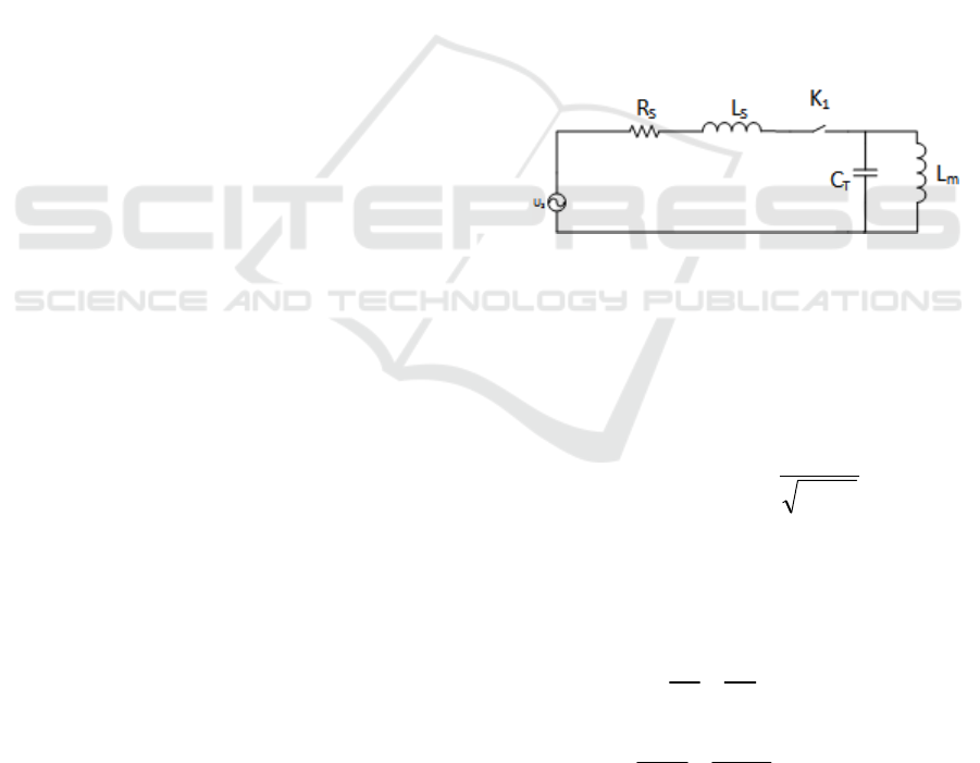
As shown in figure 1, this is the overvoltage
equivalent circuit schematic diagram of high-speed
emu operating circuit breaker. The circuit breaker is
equivalent with switch K1, where US is the traction
substation supply voltage. Catenary is equivalent in
terms of centralized parameters. The resistance and
inductance of catenary conductor are RS
respectively, LS represents. The excitation
inductance of the traction transformer is Lm, and CT
is the equivalent distributed capacitance of the high-
voltage cable core to the vehicle body. In general,
CT value is very small.
Figure 1: Operation circuit breaker overvoltage equivalent
circuit diagram.
When switch K
1
is opened, assuming the current
value is I
m
before the zero crossing of L
m
, then the
voltage value at both ends of the equivalent
capacitor C
T
is U
m
. After the current is truncated, the
LC circuit will have high-frequency oscillation. Self-
oscillation frequency is .
Since the C
T
value is small, when all the
magnetic field energy is converted into electric field
energy instantaneously, the capacitor C
T
will have a
large overvoltage. The circuit equation is as follows:
(1)
The initial condition is ,
by solving the above equation:
Tm
CL
1
0
22
2
1
0
d1
0
T
m
mT
du
Cudt
dt L
u
u
dt L C
00
)0( ,)0( UuIi
FITS 2020 - International Symposium on Frontiers of Intelligent Transport System
58
(2)
The maximum over-voltage amplitude at both
ends of the equivalent capacitance to earth is:
(3)
According to the above equation, the maximum
overvoltage at both ends of the equivalent
capacitance to earth is related to the closure phase
Angle and the high-frequency oscillation frequency.
When the phase Angle is 0° and 180°, the minimum
over-voltage amplitude of the circuit breaker when it
is opened is Um; When the phase Angle is 90° and
270°, the amplitude is the largest, and the maximum
operating overvoltage is Um f0 /f. Among them, the
high-frequency oscillation frequency f0 is related to
the electrical parameters of traction transformer and
high-voltage cable. (David D. Shipp, et.al, 2012)
2.2 Model Building
The model can be modeled from six modules
including traction substation, catenary, high-voltage
system, vehicle body, high-voltage cable and
connection model. After the circuit model modeling
is completed, the high-voltage cable and vehicle
body can be connected to the circuit to complete the
construction of the overall model.
(1) Traction substation
Traction substation, as a connection between the
power system and the traction network of electrified
railway, functions to convert the power supplied by
the power system into the power suitable for electric
traction and its power supply mode, among which
the core equipment is the traction transformer in the
substation. In practical calculation, the traction
substation can be equivalent to a power supply with
internal impedance, as shown in figure 2.The size of
each parameter is:
(4)
Figure 2: equivalent model of traction substation.
(2) Catenary
As the train's special working condition usually
occurs in the bullet train station or station, which is
far from the traction substation, the length of the
taking-power arm is 25km.According to the typical
parameters of the traction network, set the catenary
wire resistance value is 4.45 Ω, inductance value is
35.7 mH, the capacitance between rail is 0.1342 u F,
rail backflow resistance value is 1.0125 Ω, reflux
inductance value is 3.24 mH, equivalent model is
shown in figure 3.
Figure 3: Equivalent model of traction network.
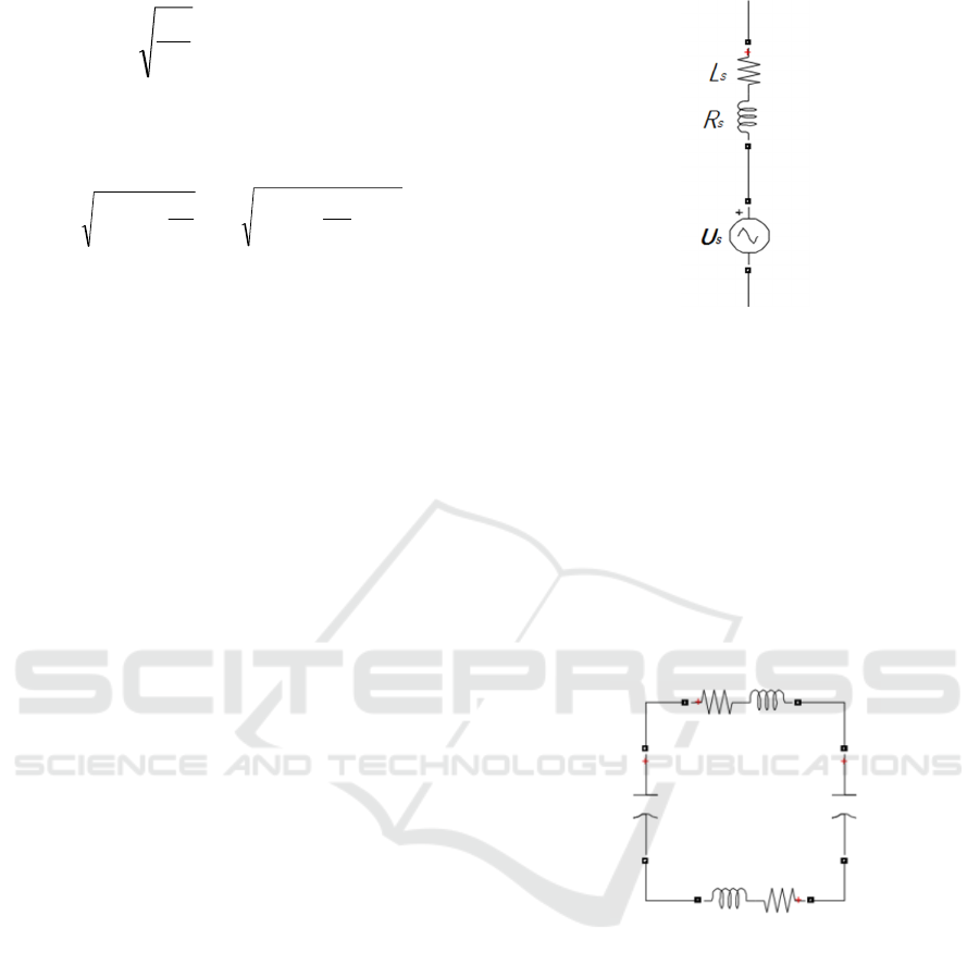
(3) Grounding module
In this model, each vehicle's protective
grounding circuit is equivalent to two protective
grounding circuits at the front and rear of the
vehicle. The impedance between each connection
point is calculated by the unit resistance and the unit
inductance of the rail. The overall equivalent circuit
diagram is shown in figure 4. The circuit in the black
box represents 3 cars' protective grounding, while
the circuit in the red box represents 3 cars' working
grounding. The parameter values are arranged as
shown in table 1.
tUt
C
L
Iu
T
m
0000
cossin
2
2
2
0
2
2
0
2
0
sincos
f
f
U
C
L
IUU
m
T
m
s
s
s
U =38.89sin100
R =0.165Ω
L=10.8mH
;
;
;
Simulation Analysis of Vehicle Body Overvoltage Caused by EMU Operating Main Circuit Breaker based on 3D Vehicle Body Modeling
59
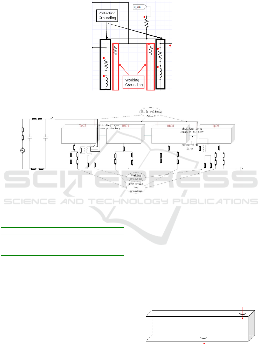
Figure 4: Schematic diagram of ground circuit.
Figure 5: Schematic diagram of the model.
Table 1: Grounding parameter values.
Parameters to describe Parameter value
Protective ground resistance 0.11Ω
Protective ground inductance 8.6uH
Working ground resistance 6.5mΩ
Based on the above judgment, the overvoltage
model of vehicle body was established. As the high-
voltage cables are distributed in 3-6 vehicles, the
simulation diagram of 3-6 vehicles is presented as
follows.
This model uses Q3D and Simplorer under
ANSYS platform to conduct solid modeling of the
high-voltage cable and vehicle body model, obtain
the distribution parameters between each part, then
import them into Simplorer for circuit connection,
and preliminarily obtain the over-voltage simulation
results.
2.3 Three-dimensional Modeling of
Vehicle Body ad High-Voltage
Cable
The simplified model of the car body ignores the
parts that have little influence on the overvoltage,
such as the seat, inner assembly and small parts. In
order to obtain the impedance parameters of each car
body, ports are set on the roof and bottom of each
car to represent the current inflow and outflow,
respectively. The schematic diagram of the model is
shown in figure 6.
Figure 6: Vehicle body setting.
FITS 2020 - International Symposium on Frontiers of Intelligent Transport System
60
The inner and outer conductors are drawn
according to the actual size of the high-voltage cable
and the actual wiring condition, and the influence of
the medium layer is ignored. The specific model is
shown in figure 7 and figure 8.The inner and outer
conductors are set as current paths respectively.
Figure 7: Distribution of high-voltage cables.
Figure 8: Section of high pressure cable.
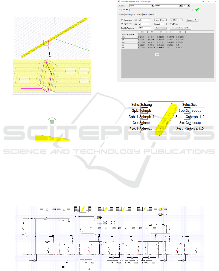
After the simulation in Q3D software is
completed, the distributed parameter results of the
model can be obtained by taking three vehicles as an
example, as shown in the figure below.
After encapsulating the Q3D model, import it
into circuit simulation software Simplorer, as shown
in figure 10. This module has taken into account the
influence of distribution parameters. Each port on
the module, namely the port set in Q3D, can be
connected to the circuit through the port.
Figure 9: Distribution parameter matrix.
Figure 10: Q3D packaging module.
2.4 Overall Model Building
According to the above mentioned traction
substation, catenary, high-voltage system, vehicle
body and grounding system model, connect the
high-voltage cable to the vehicle body circuit.
Figure 11: Overall simulation model.
Simulation Analysis of Vehicle Body Overvoltage Caused by EMU Operating Main Circuit Breaker based on 3D Vehicle Body Modeling
61
Details are as follows: the body port diagram is
shown in figure 12. The bottom of each car is
grounded through the grounding impedance, and the
workshop connection wire is connected through the
resistance.
Figure 12: Vehicle body port connection diagram.
3 ANALYSIS OF SIMULATION
RESULTS
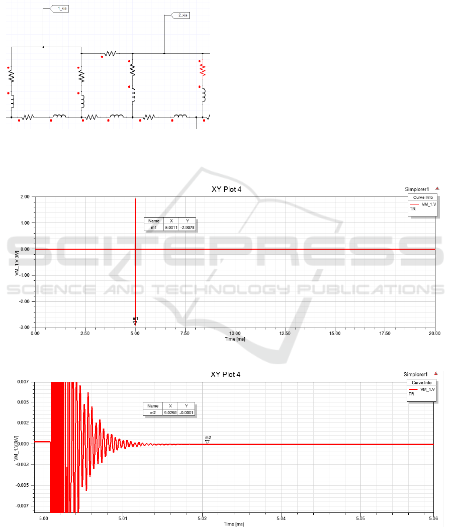
The simulation setting is VCB shutdown at 5ms. The
simulation results of overvoltage of 3 vehicles are
shown in figure 14. The generated overvoltage is
around 2.9kv, the oscillation time is around 25us,
and the main spectrum is 1.62MHz.The basic
characteristics of vehicle body overvoltage are: the
amplitude is between 3kV and 5kV; he oscillation
time is tens of microseconds. The main frequency
distribution is 1MHz-2MHz. (Wan Yusu, 2017)
Through the establishment of vehicle body and cable
entity model, import circuit software to replace part
of the structure of the existing overvoltage circuit
model, after the simulation, the overvoltage time
domain waveform and frequency domain waveform
are obtained, and the analysis of the waveform
conforms to the characteristics of the typical
overvoltage waveform, which can demonstrate the
correctness of the model.
Figure 13: Vehicle body overvoltage waveform.
Figure 14: Duration of overvoltage of vehicle body.
FITS 2020 - International Symposium on Frontiers of Intelligent Transport System
62

Figure 15. Spectrum of overvoltage of vehicle body.
4 SUMMARY
Based on the three-dimensional vehicle body model,
this paper carried out the simulation modeling
analysis on the over-voltage of the vehicle body
caused by the main circuit breaker operated by
standard emu. The traditional equivalent method of
equating the body with the four-side impedance is
broken, and the over-voltage performance of the
body of emu is analyzed and predicted.
Based on the modeling method proposed in this
paper, the obtained vehicle body overvoltage is
around 2.9kv, the oscillation time is around 25us,
and the spectrum is mainly 1.62mhz, which
conforms to the basic characteristics of overvoltage.
Therefore, the simulation modeling method
proposed in this paper can simulate and analyze the
overvoltage of the vehicle body caused by the
operation of the main circuit breaker, and realize the
analysis and prediction of the overvoltage
performance of the emu body, so as to guarantee the
safety of electromagnetic compatibility of the emu.
REFERENCES
DING Yong. Simulation analysis & experimental
verification of switching overvoltage characteristics of
HS EMU car bodies [J]. China Railway, 2017(09):68-
72+78.
HATSUKADE S, MAEDA T. Experiment and basic
analysis of surges on a rolling stock’s body [J]. IEEJ
Transactions on Power and Energy, 2005, 125 (8):
754.
High-speed trains. Glickenstein, Harvey. IEEE Vehicular
Technology Magazine. 2009.
2* 25-kV 50 Hz High-Speed Traction Power System:
Short-Circuit Modeling. Luigi Battistelli, Mario
Pagano, Daniela Proto. IEEE Transactions on Power
Delivery. 2011.
Vacuum Circuit Breaker Transients during Switching of
an LMF Transformer. David D. Shipp, Thomas J.
Dionise, Visuth Lorch. IEEE Transactions on Industry
Applications. 2012.
Wan Yusu. Study on characteristics and influence
mechanism of operating overvoltage of high-speed
emu [D]. Southwest jiaotong university, 2017.
Yan Jiabin, Zhu Feng, Li Jun, Sha Miao, Yuan Deqiang.
Electromagnetic interference measurement and
analysis of high-speed electric multiple units speed
sensor [J]. Journal of Electronic Measurement and
Instrumentation, 2015 (3): 433.
Simulation Analysis of Vehicle Body Overvoltage Caused by EMU Operating Main Circuit Breaker based on 3D Vehicle Body Modeling
63
