
Design of Neck Protection Guards for Cricket Helmets
T. Y. Pang
a
and P. Dabnichki
School of Engineering, RMIT University, Bundoora Campus East, Bundoora VIC 3083, Australia
Keywords: Cricket, Helmet, Neck, Guard, Design.
Abstract: Cricket helmet safeguards have come under scrutiny due to the lack of protection at the basal skull and neck
region, which resulted in the fatal injury of one Australian cricketer in 2014. Current cricket helmet design
has a number of shortcomings, the major one being the lack of a neck guard. This paper introduces a novel
neck protection guard that provides protection to a cricket helmet wearer’s head and neck, without restricting
head movements and obstructing the airflow, but achieving a minimal weight. Adopting an engineering design
approach, the concept was generated using computer aided design software. The design was performed
through several iterative processes to achieve an optimal solution. A prototype was then created using rapid
prototyping technology and tested experimentally to meet the objectives and design constraints. The
experimental results showed that the novel neck protection guard reduced by more than 50% the head
acceleration values in the drop test in accordance to Australian Standard AS/NZS 4499.1-3:1997 protective
headgear for cricket. Further experimental and computer simulation analysis are recommended to select
suitable materials for the neck guards with satisfactory levels of protection and impact-attenuation capabilities
for users.
1 INTRODUCTION
Cricket helmets were introduced into the sport to
protect the head and face of batsman when a bowler
intentionally aimed the ball at head height. The ball
can reach speeds of up to 160 km/h (Mohotti et al.
2018). The helmets are engineered to disperse the
kinetic energy of the ball on impact over a wider
surface area to minimize the pressure and to prevent
the likelihood of skull fracture or fatal head injury
(Subic et al. 2014). Most helmets today are generally
made of two components: a stiff shell to spread the
impact force, and a soft liner to absorb the impact
energy (Ranson et al. 2013). These two components
are generally a fiberglass or ABS (Acrylonitrile
butadiene styrene) shell and a low-density
polyethylene. A faceguard is an additional component
that attaches to the cricket helmet to protect the head
and face from impact injuries (Subic et al. 2005).
While every manufacturer develops their own design,
all have to comply with the Australian Standard
AS/NZS 4499.1-3 (Australian/New Zealand Standard
1997). Still, there are areas for the current helmet to
be improved in order to provide further protection for
a
https://orcid.org/0000-0002-4766-3042
head and facial injuries (Ranson et al. 2013). Stretch
(2000) conducted an experiment on six different
helmets with different features and materials at three
different locations. Of 18 impact sites, only 14 met
the safety standards of head deceleration below 300g
when the ball impacting at the helmeted head at a
speed of 160 km/h—a speed that a professional
bowler is capable of achieving. This suggests that the
design parameters are not the same across
manufacturers and, hence, performance varies.
An earlier study by Ranson et al. (2013) noted
limitations with the current cricket helmet designs
where the neck and basal skull as the occiput regions
are not protected. In this study, 17% of injuries
occurred at the back of the skull and 6% occurred at
the neck where there was no contact with the helmet,
as shown in Table 1. A report published on injuries in
cricket by Walker et al. (2010) stated that head
injuries account for 23% of all cricketing injuries. Of
these injuries, 35% were fractures, 18% were
contusions, 12% were sport related concussions and
11% were open-wound injuries. Similarly, a recent
study by Panagodage Perera et al. (2019) reported a
178
Pang, T. and Dabnichki, P.
Design of Neck Protection Guards for Cricket Helmets.
DOI: 10.5220/0010021101780186
In Proceedings of the 8th International Conference on Sport Sciences Research and Technology Support (icSPORTS 2020), pages 178-186
ISBN: 978-989-758-481-7
Copyright
c
2020 by SCITEPRESS – Science and Technology Publications, Lda. All rights reserved
high incidence of head injuries among female cricket
players who required hospital admissions.
Table 1: The number of injuries associated with each
impact (Ranson et al., 2013).
Area of impact Injuries % Injuries
Faceguard 9 26
Peak and faceguard 9 26
Back of shell 6 17
Temple-protector 5 14
Through peak-faceguard gap 4 11
Occiput/neck (no helmet
contact)
2 6
Total 35 100
The lack of neck and basal skull protection offered
by current cricket helmets raised serious concerns,
especially during the 2014 Australian One-Day
International cricket event. Phillip Hughes, an
Australian cricketer sustained fatal injuries after a ball
hit his neck caused a haemorrhage. Hughes was
wearing an older helmet designed by Masuri®, where
the neck and basal skull were exposed and the blunt
force caused a vertebral artery dissection leading to
subarachnoid haemorrhage (Coverdale 2014).
Subsequently Masuri, developed a new
StemGuard design. The StemGuard is made from
thermoplastics and dense foam arranged in a
honeycomb (Masuri 2015). It is an additional product
with a clip attachment to their Vision Series helmets.
Its design provided an ergonomic and practical option
to protect the neck and basal skull region (Masuri
2015). The StemGuard is currently used by world
class cricketers. Little information has been released
on how the StemGuard was tested and how much
energy it can absorb. The StemGuard is shown in
Figure 1.
Figure 1: Masuri’s StemGuard (Source: Masuri 2015).
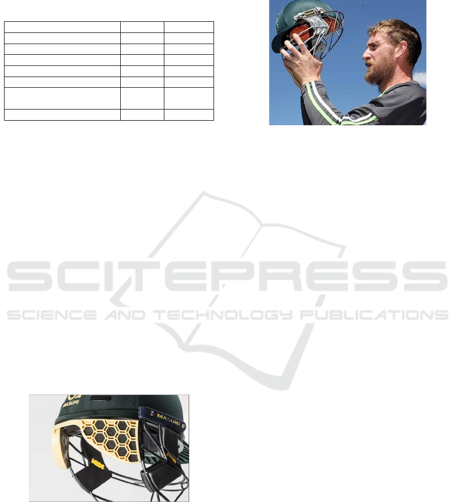
An Irish cricketer, John Mooney, has invented an
adjustable grill that extends to the back of the helmet,
to provide additional protection to the neck (Figure
2). He based the design on the medieval armour that
providing protection to the users around the throat
and neck regions. The grill was made out of steel, but
has yet been fully tested to confirm its safety
performance (Brettig 2015).
Figure 2: Adjustable grill neck protector (Source: Brettig
2015).
The aim of this project is to design and optimise a
neck protection guard (NPG) for a cricket helmet that
provides protection to the basal skull and neck
regions. Based on the knowledge gained from the
Masuri’s StemGuard concept, we aim to: (i) create a
NPG design for a cricket helmet to ensure that the
basal skull and neck region are protected; (ii) simulate
impact tests using the finite element analysis to
investigate the performance the NPG; and (iii)
produce a prototype of the proposed design and
conduct experiments for validation.
2 METHODOLOGY
To achieve these aims, an engineering design process
was adopted. The computer aided design (CAD)
software, CATIA, was used to create a 3D design of
the proposed NPG. Finite Element Analysis (FEA)
was used to perform virtual impact tests. A 3D model
representation of the NPG with realistic material
properties, boundaries and loading conditions was
devised for impact simulation. FEA was performed to
determine whether the initial design fulfilled the
impact performance and to reduce physical testing.
2.1 Concept Designs
Several concepts were proposed at the initial stage of
the design process, with consideration of a range of
design criteria and objective functions. The objective
functions for the design were: (i) the ability to protect
the neck region from impact injury; (ii) the proposed
NPG must be lightweight and flexible, yet rigid
enough to maintain its shape; (iii) it must have
adequate ventilation that will not prevent heat
Design of Neck Protection Guards for Cricket Helmets
179
dissipation from the covered region; and (iv) the
proposed design should not restrict any head and neck
movement and so be detrimental to the player’s
performance. A collection of the initial conceptual
designs is shown in Figure 3.
Figure 3: Conceptual sketches of the neck protection guard.
The design idea of the NPG was to provide
sufficient protection towards the neck and basal skull
region and could be easily attached to the faceguard.
2.2 Impact Energy and Force
When designing the NPG, it was expected the device
will withstand the impact force in the real sports
environment. Since the impact force at the basal skull
region is unknown, we used the Momentum
Conservation and Newton’s Law to determine the
impact energy and impact force.
Professional bowlers are able to throw the cricket
ball at speeds reaching 160km/h, which is equivalent
to ~44m/s. If we used this speed as an impact velocity,
we were able to determine the kinetic energy, shown
in the formula below:
1
2
(1)
The mass of the cricket ball varies with different
manufacturers. Using the Australian Standard
AS/NZS 4499.1-3:1997, the mass of cricket balls
vary from 156g to 163g.
When a force is moving the cricket ball in a linear
direction, the work is equal to the force multiplied by
the distance:
(2)
If the acceleration is constant when cricket ball is
slowing down, we can utilise the equations of motion
to calculate it corresponding velocities:
2 (3)
where u is the initial velocity, v is the final velocity, a
is the acceleration of the cricket ball and d is the
displacement.
Based on the Newton’s second law, we are able to
solve for the acceleration:
(4)
(5)
Substituting eq. (5) into (3), we get
2
(6)
Re-arranging eq. (6) to solve for F
2 (7)
1
2
(8)
From eq. (8) we are able to see that the work done
on an object is equal to the change in kinetic energy.
The linear momentum of an object is the product
of its mass and velocity:
(9)
From eq. (4)
∂v
∂
t
(10)
and hence
(11)
which states that the total force acting on an object is
equal to the time rate of change of its linear
momentum. Imagine that the force acting on the
cricket ball between t
1
and t
2
, eq. (11) can then be
integrated in time to obtain:
(12)
Δ∆
(13)
This is called the linear impulse on an object and
is assumed to be constant throughout the duration.
According to Russell (2011), the force exerted on
the ball during impact is not constant, but follows a
sine-squared time history, as shown in Figure 4.
Figure 4: Example of a Force-Time function of a collision
(Russell 2011).
icSPORTS 2020 - 8th International Conference on Sport Sciences Research and Technology Support
180
Impulse forces vary with respect to time, when the
average force, F
ave
, may obtain by integrating the
force over the contact time period. Making an
assumption that the impulse is given, then:
sin
(14)
From Figure 4, we can see that there is a
maximum force during impact that is larger, but for a
shorter time span. The area beneath the assumed
impulse response is equal to the impulse determined
from
the change of linear momentum. Thus,
sin
(15)
2.3 Finite Element Analysis
2.3.1 Static Structural Analysis
In order to evaluate the structural performance of the
concept design, the honeycomb and lattice model was
subjected to static load based on the estimated impact
force. An isotropic plastic material with a Young’s
modulus of 2.2GPa, a Poisson’s ratio of 0.38 and with
no yield stress was selected.
Figure 5: Lattice concept under static loading conditions.
The calculated maximum impact force of 31kN
was applied on the outer surface of the NPG. The tabs
that connected to the helmet were restrained in all
translations (x, y, z) and rotational about y and z axis
(Figure 5).
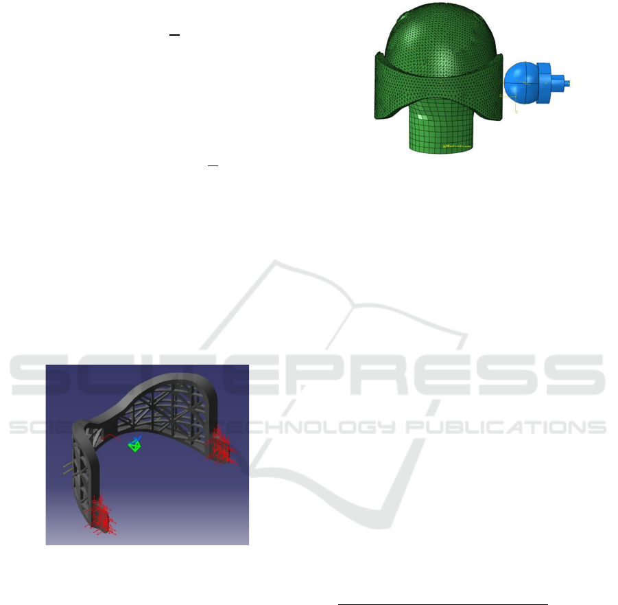
2.3.2 Dynamic Impact Simulation
Figure 6 shows the FEA set-up of the basic cricket
helmet with the stem-guard attached, placed on a
small size headform. The geometric model of the
helmet was created by using a commercially available
cricket helmet (Premiere98) with 55-58cm
circumference. The FEA was performed using e
ABAQUS® to identify the areas on the surfaces that
are in contact, and to obtain the contact generated
pressures.
.
Figure 6: Finite element analysis setup for the impact
analysis.
The cricket ball was modelled as a solid hyper-
visco plastic homogeneous part. The helmet and the
NPG were modelled with ABS materials, and the
headform was considered rigid. A general contact
was defined between all the contacting surfaces.
2.4 Safety Performance Test
All the cricket helmets sold in Australia need to
comply to the Australian Standard AS/NZS 4499.1-
3:1997 protective headgear for cricket. The
Australian Standard AS/NZS 4499.1-3:1997 states
that a cricket ball with a circumference between
224mm and 229mm and a mass of 156g to 163g must
be dropped from a 2m height to impact a bare
headform. The impacted headform must have a mean
deceleration between 400g and 500g (AS/NZS
2512.3.2). When a cricket helmet is placed on the
headform, the difference between the maximum
deceleration on the helmet and the mean deceleration
of the bare headform, must be at least 25% at the
temple, forehead, rear test area.
Percen
t
differen
t
Meandecelearation
bareheadform
Maximumdecelearation
testsite
Meandecelearation
bareheadform
100%
(16)
The detail of the test set up can be found in Pang
et al. (2013).
3 RESULTS
The result of the engineering design approach, the
FEA and the experimental results were used to
determine the effectiveness of the novel NPG design.
Design of Neck Protection Guards for Cricket Helmets
181
3.1 Concept Designs
The 3D model was initially designed a solid piece
with a variable cross-section following the curve of
the helmet, shown by the line cutting across the
surface (Figure 7a).
(a) Initial Concept (b) Lattice, (c) Honeycomb
Figure 7: 3D design of the neck protector guard.
Starting with the initial design concept of two thin
walled surfaces, the initial model was a solid piece
with a variable cross-section following the curve of
the helmet. The NPG utilised the existing faceguard
attachment point of the helmet. The concept design
underwent several iterations to fulfil the design
objective of overall weight reduction through using a
lattice pattern (Figure 7b) and also a honeycomb
pattern (Figure 7c). The overall weight reduction by
implementing the lattice and honeycomb patterns was
46.6% and 44.3%, respectively.
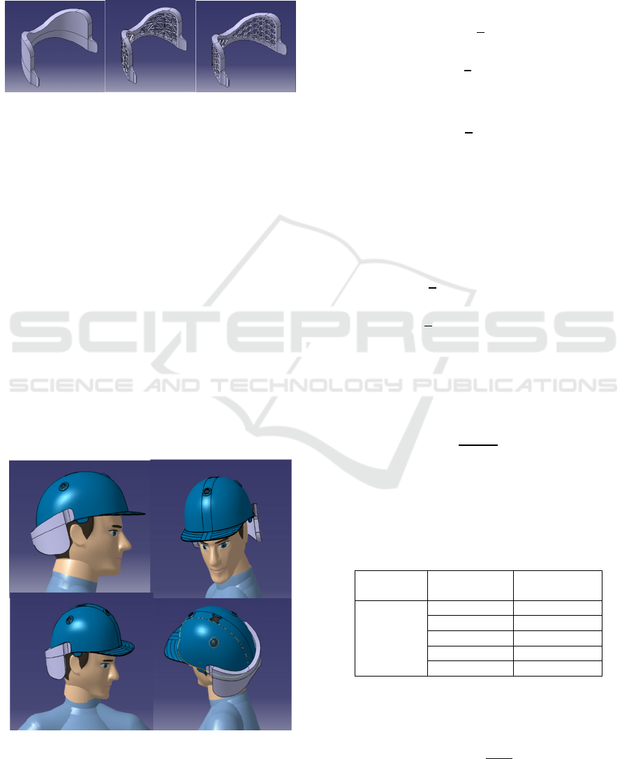
The ‘Human Posture Analysis’ in CATIA
software was used to determine the ergonomic
aspects of the NPG. Figure 8 shows a fifty percentile
American male wearing a cricket helmet with the
proposed NPG. We analysed whether the NPG design
may restrict any head and neck movements, and to
ensure there was enough space for the neck when
tilted backwards.
Figure 8: Ergonomic analysis of the neck protector guard.
3.2 Impact Energy and Forces
3.2.1 Impact Energy
Using the maximum and minimum weights, we were
able to determine the corresponding kinetic energy of
the cricket ball using eq. (1) as demonstrated below:
1
2
1
2
.156
44
151
1
2
.163
44
157.78
3.2.2 Impact Force
In order to achieve a suitable design solution that
could absorb the impact energy using eq. (8) with the
final velocity, v, is 0 and (6) is simplified as follows
1
2
1
2
0
44
968
(17)
As solved in Section 3.2.1, the kinetic energy was
157.78J. Substituting the maximum weight energy
into eq. (17), we obtained:
157.78
(18)
The average force, F
ave
, was determined
depending on the amount of deformation/
displacement of the impacted surface (Table 2),
varying from a displacement of 20mm to 1mm.
Table 2: Range of Forces with respect to Displacement.
Kinetic
Energy (J)
Displacement
(mm)
F
ave
(N)
157.78
20 7889
15 10518.7
10 15778
5 31556
1 157780
Using eq. (9) solving for impulse, we obtained:
.163
44
7.172
icSPORTS 2020 - 8th International Conference on Sport Sciences Research and Technology Support
182
The contact time with respect to average force is
presented in Table 3.
Table 3: Contact time with respect to average force and
impulse.
Kinetic
Energy (J)
F
ave
(N) Impulse Time (ms)
157.78
7889
7.172
0.909
10518.7 0.682
15778 0.455
31556 0.227
157780 0.0455
As stated in eq. (15), impulse forces vary with
respect to time, and the peak force can be determined
as:
7.172
sin
Table 4 shows peak force
calculated with the
corresponding average force and contact time.
Table 4: Peak forces with respect to average force.
F
ave
(N) Time (ms) Peak Force (kN)
7893.5 0.909 15.8
10524.67 0.682 21.0
15787 0.455 31.6
31574 0.227 63.1
157870 0.0455 315.6
The peak impact force to achieve a deformation
of 10mm was used to determine the structural
performance of the NPG under static load.
3.3 Finite Element Analysis
3.3.1 Static Load
Using generative structural analysis involving
CATIA, we were able to determine and compare the
local stresses and displacement of each design (Figure
9).
When comparing the lattice and honeycomb
designs, the honeycomb design was slightly heavier
than the lattice design. The honeycomb exhibited a
greater displacement, slightly higher localized
stresses, but lower global strain energy as shown in
Table 5.
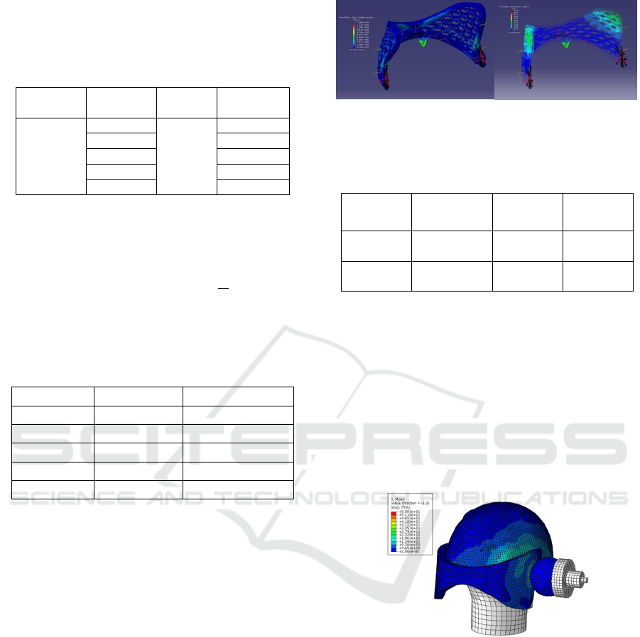
Figure 9: Stress distribution of honeycomb design under
static loading conditions.
Table 5: Comparison of honeycomb and lattice designs in
term of deformation, stress and strain from FEA.
Displacement
(mm)
Von Mises
Stress (MPa)
Strain
Energy
Lattice
Structure
39.6 1150 160.194
Honeycomb
Structure
48.8 1300 123.205
3.3.2 Dynamic Impact
Figure 10 shows the FEA of the cricket ball impacting
the NPG. The stress when the ball was impacting the
NPG was taken at the point of contact, and the kinetic
energy of the ball on impact was dispersed over a
wider surface area through the NPG. The deceleration
results from the FEA simulations (Figure 11) were
used to compare different NPG design solutions, and
to drive further design modification for
improvements.
Figure 10: FEA simulation the cricket ball impacting the
neck protection guard.
To be considered as an acceptable design
solution, the deceleration recorded at the impact site
on the NPG should not be less than 25% when
compared with the cricket ball impacting on the bare
headform as calculated from eq. (16).
Design of Neck Protection Guards for Cricket Helmets
183
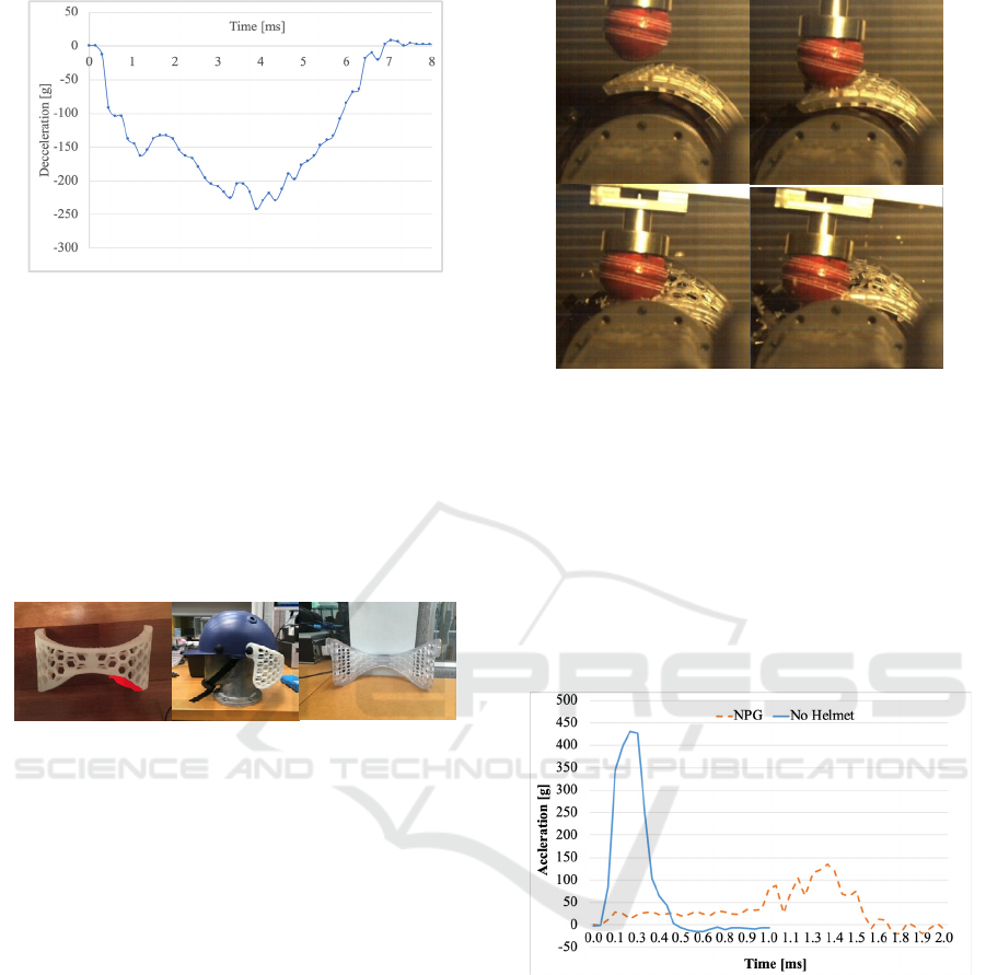
Figure 11: The deceleration of cricket ball impacting NPG.
3.4 Prototype
Figure 12 demonstrates the printed NPG protype
using ABS plastic via fused deposition modelling
(FDM) 3D printing technology. The first 3D printed
prototype was attached to the helmet and its shape
needed to be modified (the areas marked as red
needed to be removed). The tabs that connect to the
helmet were altered so that the curvature did not clash
with the helmet and faceguard.
Figure 12: 3D printed neck protection guard.
After this modification, the final design was 3D
printed to produce prototypes for a series of impact
tests to determine the functionality and their impact
performance.
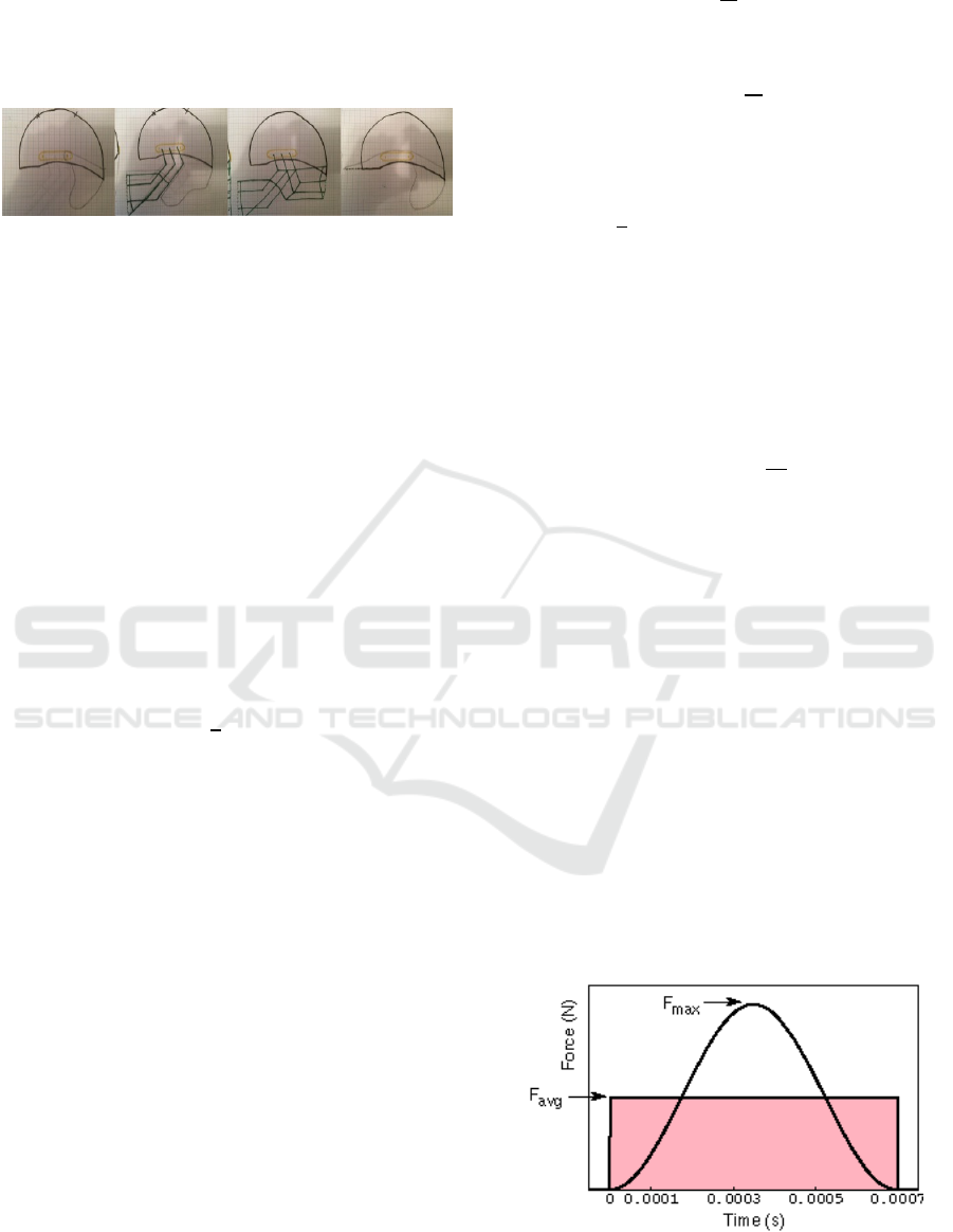
3.5 2-wire Drop Test
The experimental drop test set up conformed to
Australian Standard AS/NZS 2512.3.2 guidelines. A
striker (i.e. cricket ball) of 1.56kg. with an
accelerometer positioned within the fixture was used
to measure the deceleration at impact sites. Figure 13
shows the impacted images, captured using a high-
speed camera, of the cricket ball dropped from the 2m
above the point of impact that resulted in 30J of
kinetic energy, progressing from the initial impact
until the kinetic energy was fully transferred and
dissipated by the NPG.
Figure 13: High speed camera images of the cricket ball
impacting the 3D printed neck protection guard.
The peak accelerations of the bare headform
without a helmet and with the helmet and NPG
impacted with the 1.56kg striker are shown in Figure
14. The NPG reduced the peak acceleration, which
could cause brain injuries, from more than 400g to
approximately 150g. The mean decelerations as
calculated via Equation (1) indicated that the lattice
design and honeycomb designs managed to achieve a
maximum reduction of 70% and 59.6%, respectively.
Figure 14: Peak acceleration from drop test when the striker
impacting a bare headform and on the NPG.
4 DISCUSSION
4.1 NPG Design Development
Followed the initial concept from Masuri’s
StemGuard, a set of design criteria and objectives
were selected to drive the design and development of
the novel NPG. The novel NPG was intended to
provide protection, absorb the impact force and
promote rapid deceleration of the ball in the shortest
possible distance. A cricketer needs to react and move
icSPORTS 2020 - 8th International Conference on Sport Sciences Research and Technology Support
184

quickly to duck, weave and play shots; hence, it is
important that the new NPG added as little weight as
possible that did not impede the user’s performance
by allowing fluid head movement on the field. A
significant increase in mass would increase stress on
the user’s neck and shoulder muscles that control and
move the head. Cricket is typically played in the
hotter months. With an additional guard around the
neck, the air flow might also be restricted, and
significant thermoregulation issues could occur.
Thus, the new NPG should promote good air flow to
ensure the user remains comfortable and not overheat.
Having these clear design criteria, a base concept
of two thin-walled surfaces was developed, a further
design iteration was added to reduce the overall NPG
weight, and the lattice pattern and honeycomb
patterns were created (Figure 4). The patterns also
allowed air to pass through and minimised the
insulated heat for the users by permitting air to
circulate around the neck region.
CAD software, ABAQUS and CATIA Human
Posture Analysis, were used to investigate the
proposed NPG designs in terms of their ergonomics
and structural behaviour. The central bridge areas of
the initial NPG design were widened laterally and
narrowed in height to accommodate the neck tilt
backward movements in the final design. By
widening the bridge area, we ensured that the
protector did not clash while still providing adequate
protection to the neck region. An FEA simulation was
used to verify that the NPG components could
withstand the impact from the cricket ball at various
impact speeds prior to the physical testing. From the
FEA, we discovered that the initial designs were
slightly flexible during the impact and, hence,
additional rib structures were implemented to the
lattice and honeycomb designs to improve the overall
rigidity and maintain sufficient shape integrity during
or after movement, particularly in the moments
before a potentially catastrophic impact.
4.2 Impact Evaluation and
Recommendations
The impact force of 31kN was used to conduct the
structural analysis of the NPG design. As described
by Fuss et al. (2007) an impact velocity at roughly 44
m/s will achieve a corresponding and peak force (kN),
as shown in Figure 14.A cricket ball with a cork core
and an impact velocity at roughly 44 m/s will achieve
a corresponding maximum peak force of around 27
kN. It is worth noting that the peak force calculated
in the present study was based on the assumption that
the cricket ball is rigid, with no deformation, and the
energy and momentum are linear. However, the peak
force in Fuss et al. (2007) was based on a viscoelastic
model, which accounted for the deformation of the
cork centre and, hence, slightly lower than the
estimated force for this study.
For the experimental testing, and as proof of
concept, the prototype of the NPG was 3D printed
using ABS material, which has a slightly lower
impact strength. However, the results showed that the
NPG provided a sufficient level of impact attenuation
and protection to a wearer from head and neck injury.
We acknowledge that the ABS materials break
easily when impacted by a cricket ball. This can cause
more damage and injury to users from the remnant
plastic after the impact.
Therefore, suitable material selection plays an
important role in designing the NPG component. For
the future applications, we recommend: (i)
Polycarbonate (PC) as they are commercially
available thermoplastic materials that are light
weight, but yet have high impact strength and good
energy absorption, and which are suitable in cold and
hot weather as well as good in high humidity
environments (Caswell et al. 2007); (ii) Kevlar®
(DuPont), as they are lightweight advanced
composite materials that provide high impact and
blast-level protection, and which also play a
significant role in future athletic gear (Caswell et al.
2007)—these are, however, slightly costly to
manufacture and shape.
The NPG was only tested in laboratory conditions
according to the AS/NZS 2512.3.2 guidelines. We
acknowledge that a cricket ball of a mass of 156g to
163g dropped from a 2m height will only process a
maximum velocity of 4.5 m/s. The drop speed was
significantly slower than a fast bowler can achieved
(~44 m/s) (Stretch 2000). Therefore, it is
recommended that the NPG should be tested with a
pitching machine, as described in Pang et al. (2013),
for assessing the NPG protection performance.
5 CONCLUSIONS
The design and development of a novel NPG is
presented in this paper. The design criteria in
designing the NPG are to protect the neck and basal
skull area, to achieve a light weight, to allow
sufficient air flow and heat transfer in the protected
region and, most importantly, to secure a safety
performance that is able to dissipate impact energy
thereby reducing the blow of a cricket ball and
protecting a batsman from serious injury.
Design of Neck Protection Guards for Cricket Helmets
185

The engineering design process, an FEA for the
impact of cricket ball on the NPG, and experimental
tests results were presented. The initial conceptual
NPG designs went through an iterative process to fulfil
the design criteria and to identify improvements. The
experimental results showed more than 50% reduction
in impact deceleration with the new NPG. Future work
should be directed towards a more comprehensive
analysis, both numerically and experimentally, to
select suitable materials for NPG with satisfactory
level of protection and impact attenuation capabilities
to users.
ACKNOWLEDGEMENTS
The authors thank Giuseppe Morina and Asimina
Vanderwert for their assistance and support in this
research work. Provision of the 3D printing and
prototypes by the Advanced Manufacturing Precinct
is acknowledged. We also acknowledge the advice of
Dr Vu Nguyen from the Commonwealth Scientific
and Industrial Research Organisation.
REFERENCES
Australian/New Zealand Standard. 1997. AS/NZS
4499.3:1997. In Protective headgear for cricket Part 3:
Faceguards. Australia and New Zealand: Standards
Australian and Standards New Zealand.
Brettig, D. 2015. Mooney tests helmet with neck protection.
ESPNcricinfo.
Caswell, S. V., T. E. Gould & J. S. Wiggins. 2007.
Protective helmets in sports.
Coverdale, B. 2014. Hughs suffered extremely rare, freak
injury to neck. ESPNcricinfo.
Fuss, F. K., A. Subic & S. Ujihashi. 2007. Non-linear
viscoelectic impact modelling of cricket balls. In The
Impact of Technology on Sport II, eds. S. Ujihashi, F.
K. Fuss & A. Subic, 349-356. Taylor & Francis Group.
Masuri. 2015. StemGuard-Additional Protection for
Batsman's Neck. Masuri.
Mohotti, D., P. L. N. Fernando & A. Zaghloul (2018)
Evaluation of possible head injuries ensuing a cricket
ball impact. Computer Methods and Programs in
Biomedicine, 158, 193-205.
Panagodage Perera, N. K., J. L. Kemp, C. Joseph & C. F.
Finch (2019) Epidemiology of hospital-treated cricket
injuries sustained by women from 2002–2003 to 2013–
2014 in Victoria, Australia. Journal of Science and
Medicine in Sport, 22, 1213-1218.
Pang, T. Y., A. Subic & M. Takla (2013) Impact Energy
Attenuation Performance of Cricket Helmets: Standard
2-wire Drop Test vs. Pitching Machine Impact Test.
Procedia Engineering, 60, 143-150.
Ranson, C., N. Peirce & M. Young (2013) Batting head
injury in professional cricket: a systematic video
analysis of helmet safety characteristics. Br J Sports
Med, 47, 644-8.
Russell, D. A. 2011. Forces between Bat and Ball.
Stretch, R. A. (2000) The impact absorption characteristics
of cricket batting helmets. J Sports Sci, 18, 959-964.
Subic, A., F. Alam & M. Takla. 2014. Sports Helmets. In
Routledge Handbook of Sports Technology and
Engineering, eds. F. K. Fuss, A. Subic, M. Strangwood
& R. Mehta, 252-276. London: London: Routledge.
Subic, A., M. Takla & J. Kovacs (2005) Modelling and
analysis of alternative face guard designs for cricket
using finite element modelling. Sports Engineering, 8,
209-222.
Walker, H. L., D. J. Carr, D. J. Chalmers & C. A. Wilson
(2010) Injury to recreational and professional cricket
players: Circumstances, type and potential for
intervention. Accident Analysis & Prevention, 42,
2094-2098.
icSPORTS 2020 - 8th International Conference on Sport Sciences Research and Technology Support
186
