
Robotic Finger Design Workflow for Adaptable Industrial Assembly
Tasks
Adam Wolniakowski
1,2 a
, Anders Prier Lindvig
2 b
, Nicolai Iversen
3 c
, Norbert Kr
¨
uger
2 d
and Alja
ˇ
z Kramberger
2 e
1
Faculty of Electrical Engineering, Bialystok University of Technology, Bialystok, Poland
2
The Maersk Mc-Kinney Moller Institute, University of Southern Denmark, Odense, Denmark
3
The Maersk Mc-Kinney Moller Institute, SDU UAS Center, University of Southern Denmark, Odense, Denmark
Keywords:
Finger Design, Assembly, Simulation, Industrial.
Abstract:
In this work, we introduce a web-based system connected to a simulation framework that can be used to
facilitate the design of industrial fingers. We provide an overview of the state of the art and of the currently used
manual gripper finger design methods prevailing in the industry. With a concrete use case we demonstrate the
advantages in terms of quality and saved time for designing the fingers when utilizing our presented framework
compared to a common manual method of designing the gripper fingers.
1 INTRODUCTION
The design of fingers for industrial gripper is a ma-
jor obstacle for setting-up robot assembly solutions
(Kr
¨
uger et al., 2014). Usually for each new object
a new finger needs to be designed manually, tested
and refined in the work-cell with which the assembly
problem should be solved. In particular SMEs avoid
robot solutions because of the complexities involved
in these processes.
In earlier work (Wolniakowski et al., 2017) a so-
lution was presented for this problem by replacing the
manual processes by optimization in simulation. Sim-
ulation allows to test many variants of grippers within
a second and at the end even enable the optimization
of the shape which is expressed by means different
parameters according to externally given objectives
(such as, e.g., the ability to align objects in the grip-
per that are positioned imprecisely due to, e.g., vision
errors) (Baizid et al., 2015).
In this work, we frame our prior work such that it
is directly applicable by external companies. Based
on a web-service, the company can formulate the
problem at hand, and by means of a software that has
a
https://orcid.org/0000-0003-1698-1870
b
https://orcid.org/0000-0002-6972-0116
c
https://orcid.org/0000-0001-5491-8886
d
https://orcid.org/0000-0002-3931-116X
e
https://orcid.org/0000-0002-4830-4885
been improved in terms of ease of use as well as the
introduction of enhanced features, the problem can be
solved in rather short time.
In this paper, we show the overall process for an
industrial use case connected to the assembly of a
drone. By that, a service will be exemplified that can
facilitate the use robots in the production lines in par-
ticular SMEs.
2 STATE OF THE ART
The majority of the finger design cases, that can be
found in industrial automation, is still designed man-
ually in terms of a CAD design made by a profes-
sional engineer. The design process is usually very
time consuming and it involves an expert with in-
depth field knowledge of robot based grasping and
rich hands-on experience with the design methodolo-
gies. Due to high manufacturing costs, in the past
simple shapes, e.g. cutouts, were embedded in the
base fingers for simple robot based manipulation tasks
(see also (egr, 2020)). However, with the emergence
of modern manufacturing technologies in the sense
of additive manufacturing, more complex shapes are
easier and cost efficient to embed and manufacture,
consequently raising the complexity level of the de-
sign process, respectively. One of the biggest bottle-
necks of the hand design approach is to rely on the
Wolniakowski, A., Lindvig, A., Iversen, N., Krüger, N. and Kramberger, A.
Robotic Finger Design Workflow for Adaptable Industrial Assembly Tasks.
DOI: 10.5220/0010020100690076
In Proceedings of the International Conference on Robotics, Computer Vision and Intelligent Systems (ROBOVIS 2020), pages 69-76
ISBN: 978-989-758-479-4
Copyright
c
2020 by SCITEPRESS – Science and Technology Publications, Lda. All rights reserved
69
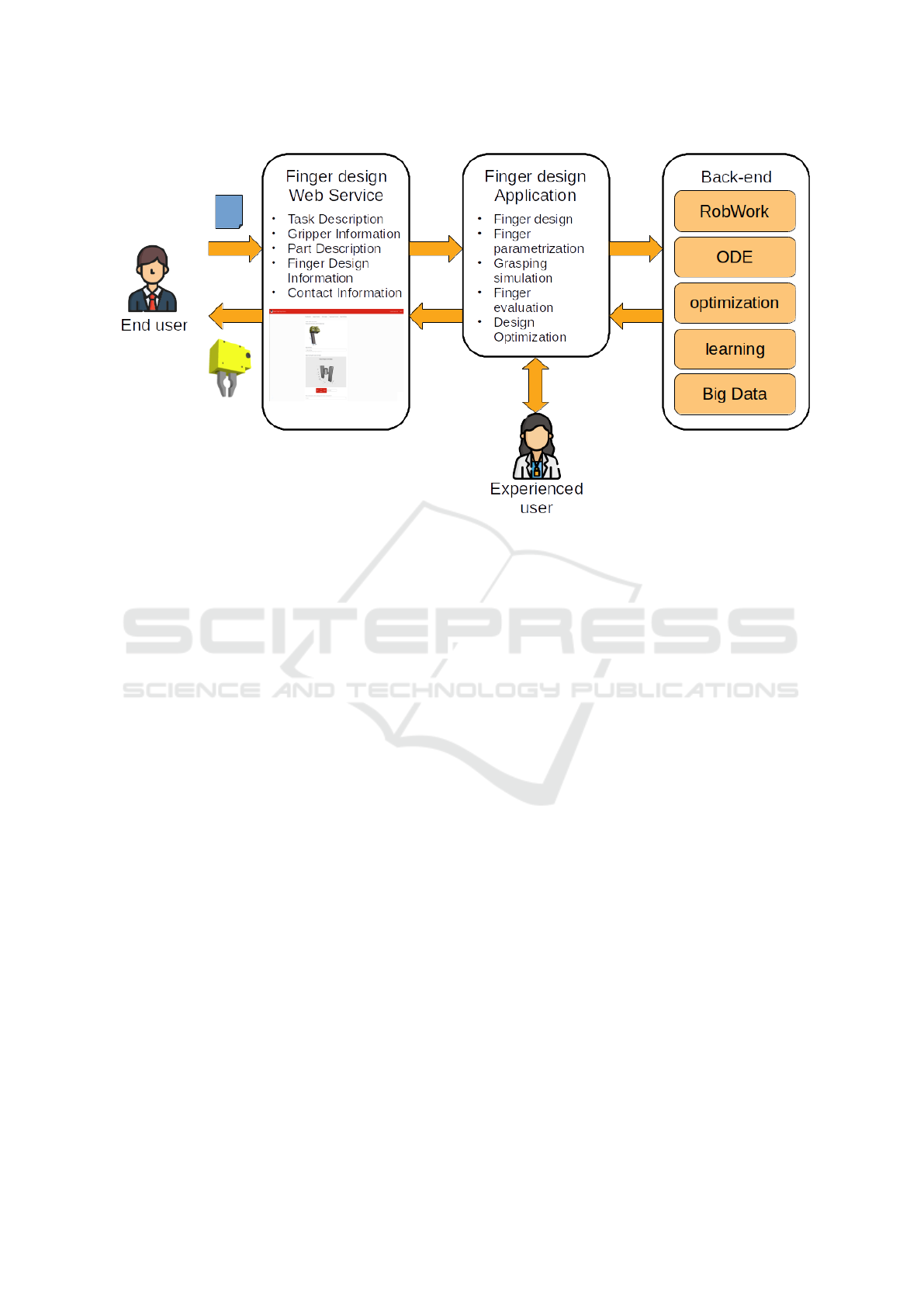
Figure 1: The overview of the proposed framework.
experience of the engineer, because tools for testing
and benchmarking the design in simulation are not yet
widely available. Therefore, the only efficient way of
testing the design is to manufacture it and test on the
real objects, which prolongs and makes the overall de-
velopment process more expensive.
The difficulty associated with finger design has
encouraged wide research effort and commercial in-
terest. Researchers have proposed gripper design
methodologies based on geometry generation, opti-
mization and simulation (Honarpardaz et al., 2016a;
Honarpardaz et al., 2016b; Gorce and Fontaine, 1996;
Cuadrado et al., 2002; Datta and Deb, 2011; Causey,
1999). Immense interest was also directed towards
grasp planning and grasp quality metrics (Zheng and
Qian, 2009; Ferrari and Canny, 1992; Kraft et al.,
2014), as well as generic robotics-centered design and
optimization (Baizid et al., 2016).
Of the commercial products made available for the
finger design assistance, worth noting is the eGRIP
tool developed by Schunk (egr, 2020). The tool takes
a form of a web application, where the user can up-
load the model of an object desired to be grasped.
The user can subsequently define various parameters
of the grasping scenario, i.e. select the gripper from
the list of Schunk produced devices, specify the rel-
ative transforms during the grasping and the object
properties, such as mass and material. The finger
shape is then generated automatically by subtracting
the object’s geometry from the blank fingers. Some
post-processing is also done in order to facilitate the
mounting and gripper clearance. The generated fin-
gers can be previewed and approved by the user, who
has an option to purchase the product online.
3 FRAMEWORK
The overall organization of our proposed framework
for adaptable gripper finger design is presented in
Fig. 1. The system consists of two main parts: the
web service serving as the end-user interface (left
side of the figure), and the off-line gripper design and
the finger design application (middle part of the fig-
ure) which relies on the domain specific dependen-
cies, such as simulation engine (ODE), optimization
methods, and previously researched learning methods
(Schwartz et al., 2017).
The web-service is used for the purpose of task
and context definition, where the end-user has the
possibility of defining in detail the problem to be
solved, i.e. specifying the object to be grasped, pre-
ferred gripper structure, desired materials etc. Base
on this end-user input, a task summary is generated,
which is then used to configure the grasping scenario
simulated and evaluated with the use of the off-line
application. The application is designed to be han-
dled by an experienced user, who can set up the simu-
lation and optimization parameters and generate eval-
uated and optimized gripper finger shapes. The user
requests and the generated designs are stored in a
database, which can subsequently be used to extract
ROBOVIS 2020 - International Conference on Robotics, Computer Vision and Intelligent Systems
70
high level features in order to further improve and
shorten the processing time of the future requests.
4 METHODS
In this section, we describe the workflow of our pro-
posed finger design system. This section is split ac-
cording to the overall system architecture presented
in Fig. 1: The web-service layer responsible for end-
user interaction is described in section 4.1, the finger
design application is described in section 4.2, and the
further back-end features are described in section 4.3.
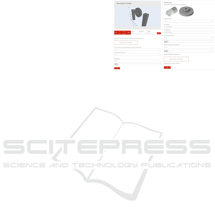
4.1 Web-service
The web-service (see Fig. 2) provides the end user
with a graphical user interface that allows for upload-
ing CAD files and enter information relevant for de-
signing fingers for a gripper. The user must provide
the following information:
• task description,
• gripper information,
• part description,
• finger design information,
• contact information.
The task description provides information about
the task performed by the robot. Gripper information
covers what gripper is to be used and details about it.
For the part description, a CAD file of the object to be
grasped should be uploaded, and details about the ob-
ject should be entered (e.g. shape, material, weight).
Finger design information should specify dimensions
(length, width, depth) of the fingers, and based on the
CAD file of the object, the user is able to manipulate
the object with respect to a set of fingers in a 3D envi-
ronment, to show how the object should be grasped. It
is also possible to upload an image of how the object
should be grasped. Finally the user provides contact
information. When the user has submitted all relevant
information, a confirmation e-mail with a detailed or-
der description is sent to the provided e-mail address.
In Fig. 2 you can see the grasp definition and the part
description sections of the web-service.
4.2 Finger Design Application
The finger design application is designed to be the
middle-layer of the proposed system that is operated
by the experienced user. The application is used to
create a specific ”finger design project” based on the
input provided through the web-service (see section
Figure 2: Web-service: grasp definition section (on the left),
part description section (on the right).
4.1). The work flow of the application is shown in
figure 3.
First, the finger design project is created that al-
lows for the organization of the data (1). In this fin-
ger design project, the environment is set-up accord-
ing to the task specification provided by the end-user.
This setup consists of four steps: (2) workcell selec-
tion (this defines the environment in which the grasp-
ing is performed), (3) importing the object (the ob-
ject to be grasped is provided by the end user), (4)
gripper selection (grippers can be selected from the
database or created by the middle user), and (5) grasp
set generation. The grasp set is defined based on the
desired grasp and the process noise expected for the
given scenario.
Next (7), it is the middle-user task to decide
on the finger parametrization and the preliminary
finger designs. These can be imported from 3D
model files generated in CAD software, or created as
parametrized Constructive Solid Geometry meshes.
These finger blanks can be easily modified for the ob-
ject grasping through the use of application features:
molded cutout and imprint based cutout (Schwartz
et al., 2017).
With the project configured as described above
(1-7), it is now possible to run grasping simulation
(8), where an evaluation of the finger design perfor-
mance is provided to the middle-user based on the
success of grasping in the previously defined grasp
set (5). Based on the feedback from this step, the user
may decide to approve the design or go back to the
parametrization step (7) and tweak the design param-
eters.
4.3 Optimization as Optional Step
While iterated finger design, simulation and evalua-
tion are often sufficient for arriving at a feasible fin-
Robotic Finger Design Workflow for Adaptable Industrial Assembly Tasks
71
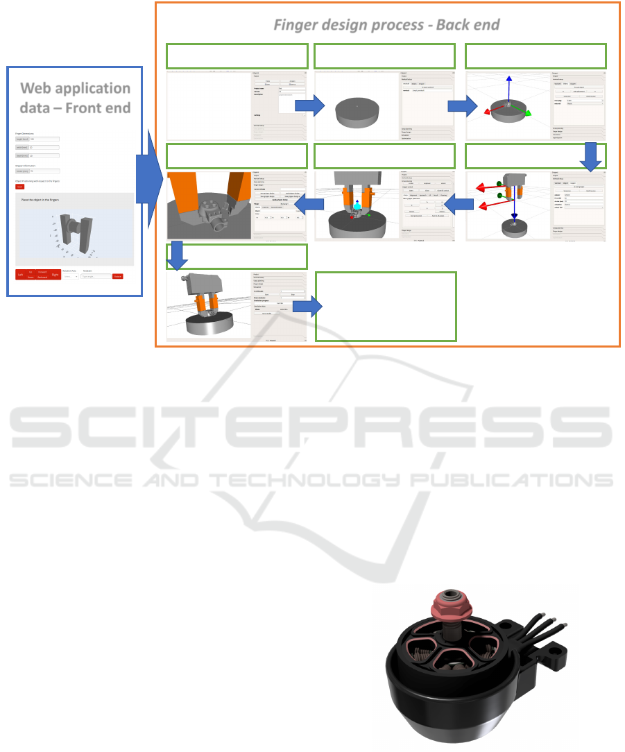
Create project Select workspace Import part
Select gripperGenerate grasp setDesign gripper finger
Simulate design
Final design
Finger design process - Back end
Web application
data – Front end
Figure 3: Finger design application workflow.
ger design, the proposed finger design system also of-
fers a possibility of employing a range of numerical
optimization methods to further supplement and au-
tomate the design process. To this end, an applica-
tion feature is currently being developed to integrate
various numerical optimization algorithms (e.g. sim-
plex, BOBYQA, simulated annealing, RBFopt, etc.,
see (Jørgensen et al., 2018)).
The experienced user will be able to set-up the
evaluation and optimization meta-parameters (8) and
create optimization tasks which can be run unsuper-
vised on the work station or a dedicated computer
cluster. The optimization results would be then eval-
uated by the experienced user before the final verdict
is made and the product sent to the end user.
The task specifications and the generated results
are going to be stored in a database, such that when
considerable amount of data is acquired, the process
can be further accelerated by extracting the common
features by employing information from the finger
design project data base and machine learning tech-
niques.
5 FRAMEWORK
BENCHMARKING
In the following section we evaluate the proposed
framework in simulation. Furthermore we will also
present and discuss the real-world implementation of
the designed fingers in an industrial assembly task.
To benchmark the proposed approach, we imple-
mented it as an service in the SDU Industry 4.0 Labo-
ratory. The aim of the laboratory is to develop new
lean production technologies, where the core func-
tionalities lie in the adaptable collaborative robot as-
sembly. The first implementation of the system is
based on a novel drone assembly, where the proposed
system is implemented in the supporting framework
for agile and flexible development of tools, needed
for the assembly to be executed.
Figure 4: Parts included in assembly task case.
The assembly task requires handling parts for
an unmanned aerial platform e.g. drone conducting
high voltage power line inspection (d4e, 2020). The
grasped objects includes a drone arm ”hub”, facilitat-
ing the drone motor as well as the landing gear. The
ROBOVIS 2020 - International Conference on Robotics, Computer Vision and Intelligent Systems
72

parts was re-designed from their initial geometry with
the objective of enhancing producibility to achieve ef-
ficient high volume manufacturing rather than proto-
typing. The results show that designing with automa-
tion in mind made the assembly process easier for
robots - but also humans.
As seen in Fig. 4 the landing gear has a square
shape and locks in place with the hub through a snap-
connection, rather than a threaded assembly. Parts
assembled in fixtures were designed with embedded
features leading to a kinematic coupling between part
and fixture during the process. The general feature
across all of the parts was to embed flat faces leading
to a simpler finger design and a higher rate of success-
ful manipulations.
The overall framework proposed in this paper was
tested on the drone motor assembly use case. The
production engineers used the front-end of the fin-
ger design framework to specify the requirements and
give information about the task specifying how the
parts are introduced to the cell, what is the task com-
prised of, grippers and robots used for the task, mate-
rials, etc. Some of the requirements given through the
front-end interface are:
• The parts arrive in the robot cell in fixtures where
their position is semi-defined.
• The parts have to be aligned in the finger to en-
sure a stable pose of the object for the following
assembly process.
• The finger acts as an fixture onto which the rest of
the sub-assembly parts have to be assembled.
• The robot has to perform various tasks, therefore
the fingers have to be exchanged when another
task arises.
• The fingers have to be manufactured through ad-
ditive manufacturing.
As mentioned before the main idea of the front-end is
to gather user information related to the task, which
has to be handled. One of the functionalities is also
the ability to upload the 3D representations of the ob-
ject and visualize how they can be grasped. This func-
tionality can be customized by the user: the user con-
figures the view (see Fig.3, web application data) until
he is satisfied with the pose of the object placed in the
mock-up gripper. This information gives the designer
using the back-end the information on the grasp pose
of the object in relation to the gripper fingers. The in-
formation is compiled and used in the back-end finger
design and evaluation procedures.
To design the suitable finger shape for the pre-
sented assembly task, we have utilized our previ-
ously introduced gripper simulation framework (Wol-
niakowski et al., 2018). The finger design framework
is based on the Open Dynamics Engine (Smith, 2005)
and a visual interface provided by RobWork (Ellek-
ilde and Jorgensen, 2010).
Furthermore, the requirement presented by the
end user is to use the fingertip exchange mechanisms
(Kramberger et al., 2019) in order to perform quick
changeovers between fingertips dedicated for differ-
ent part handling. In addition we had access to a
manual CAD fingertip designed for handling the mo-
tor assembly, by an expert engineer. Therefore, we
can compare the manual CAD design with the design
produced by the presented framework. A comparison
between the two designs is shown in Fig. 6.
The hand and the design made with the back-end
were furthermore tested in simulation in order to es-
tablish the range at which the fingers are able to com-
pensate the possible position uncertainty introduced
by the object handling before the assembly task. In or-
der to define the uncertainty and compensation map-
ping, grasps were executed in simulation with increas-
ing offset from the nominal pose along all three prin-
cipal position and orientation axis. In total 100 grasps
with offsets from the nominal prose per axis were exe-
cuted in the range from (σ
pos
= −10mm to 10mm and
σ
ang
= −5
◦
to 5
◦
). The combined simulation experi-
ment results for the two finger designs are presented
in Fig. 5. The figure is divided into two parts. The
left side represents the position and the right side the
orientation part of the conducted tests (three plots for
each of the position and orientation axes respectively)
represent the grasping success and reliability distribu-
tion for the two designs tested in simulation .
For each of the finger designs, the experiments
were executed in six batches, where in each batch the
object was displaced from its nominal pose defined by
the user along one of the axes. Each individual plot in
Fig. 5 shows the grasping success evaluated along the
individual axis (x, y, z, Rx, Ry, Rz). The solid green,
yellow and red lines represent successful, misaligned
and failed grasps for the hand designed fingers respec-
tively. Whereas the dotted blue, cyan and black lines
give the indications of the before mentioned grasp-
ing evaluation indices related to the design made by
the presented framework in this paper. The results ac-
quired with the design framework show a boundaries
of the alignment capabilities which are easily to dis-
tinguish. In comparison, in the hand design results the
boundary outlining the successfully aligned grasps is
more dispersed and cannot be easily defined.
For instance, with the experiments conducted in
the roll and pitch direction with the hand design, it
can be seen that finger design is not able to com-
pensate for the pose uncertainty repetitively, therefore
the success measures e.g. green are dispersed along
Robotic Finger Design Workflow for Adaptable Industrial Assembly Tasks
73
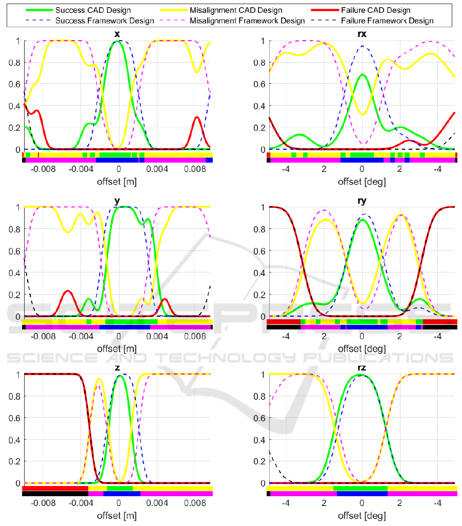
Figure 5: The evaluation results for the two sets of the finger tips designs. The solid green, yellow and red lines represent the
outcome of the experiments conducted with the CAD design approach. The dashed blue, magenta and black lines represent
the experiment outcomes based on the presented framework respectively.
the entire test range. This outlines that the tolerances
and the embedded features are not designed properly
to accommodate the part geometries. In comparison
the tests conducted with the design produced with the
presented framework, are more evenly distributed and
there is a clear border visible between the success-
ful and misaligned experiments, giving and indication
that the design is more robust and reliable in a certain
area of operation and outperforms the hand CAD de-
signed fingers.
One additional criterion for comparing the two de-
signs is also the time spent on the design process it-
ROBOVIS 2020 - International Conference on Robotics, Computer Vision and Intelligent Systems
74
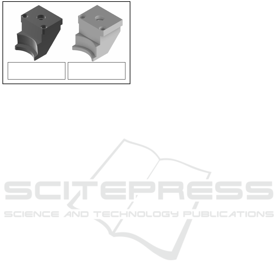
Design produced with the
framework.
Design produced by
manual CAD design.
Figure 6: Two finger tip designs used for performance com-
parison.
self. It was reported by the expert engineer that the
typical design process for a finger or fingertip takes
roughly 6 to 8 hours, depending on the complexity of
the embedded features and the number of 3D prints
needed to verify the design. 3D printing is in this par-
ticular case the only method that can be used for ver-
ification of the design before actual manufacturing.
On the other hand, if following the proposed frame-
work (Fig. 3) an initial design and a quick verification
in simulation can be executed in less than 1 h. This
approach not only saves time but also provides an in-
dication how good the design actually is, without the
need for a time consuming 3D printing step.
6 CONCLUSIONS
In this paper, we presented an end-to-end framework
for designing optimized gripper fingers for industrial
tasks. The framework takes into account the task
specification and requirements supplied by the end
user through a web-based interface. The supplied data
is analyzed and compiled in a way such it can be used
in the design process, respectively.
The strong point of the presented framework is a
significant cut down of the development time. After
the data acquired through the front-end is processed
and imported into the back-end, the design procedure
is executed semi-automatically. In comparison with
the manual design, where the relevant measurements
and constraints have to be properly prepared and set
up, the presented framework does the set-up automat-
ically and consequently speeds up the process. In ad-
dition, the only way to verify the hand design is to
manufacture the finger, thus prolonging the evalua-
tion and design process. In the presented framework,
we also have the functionality of testing the designs
in dynamic simulation environment. The tests give us
an insight on how good the design actually is, without
the need of manufacturing the finger.
The conducted experiments show that the fingers
designed with the presented framework outperformed
the hand designed fingers supplied by an expert engi-
neer. The biggest benefit of the presented approach is
to save time and the ability to evaluate the proposed
design.
In the future, we will extend the presented frame-
work to incorporate deformable materials which can
be embedded into the finger designs for better fric-
tion conditions during the grasp execution. Further-
more, although for now the front-end of the presented
framework is available for internal use only, in the fu-
ture we plan to make it available to the broader spec-
trum of users.
ACKNOWLEDGEMENT
This work has been supported by SDU Robotics’
activity funded by SDU’s I4.0 Lab. and Innovation
Fund Denmark Grant Solutions grant 8057-00038A
Drones4Energy project (https://drones4energy.dk)
and by the Polish Ministry of Science and Higher
Education in grant no. WZ/WE-IA/4/2020.
REFERENCES
(2020). Drones4energy project. https://drones4energy.dk.
Accessed: 2020-05-19.
(2020). Schunk egrip. https://www.egrip.schunk.com. Ac-
cessed: 2019-02-26.
Baizid, K.,
´
Cukovi
´
c, S., Iqbal, J., Yousnadj, A., Chel-
lali, R., Meddahi, A., Deved
ˇ
zi
´
c, G., and Ghionea,
I. (2016). Irosim: Industrial robotics simulation de-
sign planning and optimization platform based on
cad and knowledgeware technologies. Robotics and
Computer-Integrated Manufacturing, 42:121 – 134.
Baizid, K., Yousnadj, A., Meddahi, A., Chellali, R., and
Iqbal, J. (2015). Time scheduling and optimization
of industrial robotized tasks based on genetic algo-
rithms. Robotics and Computer-Integrated Manufac-
turing, 34:140 – 150.
Causey, G. C. (1999). Elements of agility in manufacturing.
PhD thesis, Case Western Reserve University.
Cuadrado, J., Naya, M. A., Ceccarelli, M., and Carbone, G.
(2002). An optimum design procedure for two-finger
grippers: a case of study. IFToMM Electronic Journal
of Computational Kinematics, 15403(1):2002.
Datta, R. and Deb, K. (2011). Optimizing and deciphering
design principles of robot gripper configurations using
an evolutionary multi-objective optimization method.
Ellekilde, L.-P. and Jorgensen, J. A. (2010). Robwork: A
flexible toolbox for robotics research and education.
Robotic Finger Design Workflow for Adaptable Industrial Assembly Tasks
75

In 41st International Symposium on Robotics (ISR)
and 6th German Conference on Robotics (ROBOTIK),
pages 1–7.
Ferrari, C. and Canny, J. (1992). Planning optimal grasps.
pages 2290–2295.
Gorce, P. and Fontaine, J. (1996). Design methodology ap-
proach for flexible grippers. Journal of Intelligent and
Robotic Systems, 15(3):307–328.
Honarpardaz, M., Tarkian, M., Feng, X., Sirkett, D., and
¨
Olvander, J. (2016a). Generic automated finger de-
sign. In ASME International Design Engineering
Technical Conferences and Computers and Informa-
tion in Engineering Conference (IDETC/CIE), volume
5B-2016.
Honarpardaz, M., Tarkian, M., Sirkett, D.,
¨
Olvander, J.,
Feng, X., Elf, J., and Sj
¨
ogren, R. (2016b). Generic
automated multi-function finger design. volume 157,
pages 12–15.
Jørgensen, T., Wolniakowski, A., Petersen, H., Debrabant,
K., and Kr
¨
uger, N. (2018). Robust optimization with
applications to design of context specific robot solu-
tions. Robotics and Computer-Integrated Manufac-
turing, 53:162–177.
Kraft, D., Ellekilde, L.-P., and Jørgensen, J. (2014). Au-
tomatic grasp generation and improvement for in-
dustrial bin-picking. In R
¨
ohrbein, F., Veiga, G.,
and Natale, C., editors, Gearing Up and Accelerat-
ing Cross-fertilization between Academic and Indus-
trial Robotics Research in Europe:, volume 94 of
Springer Tracts in Advanced Robotics, pages 155–
176. Springer International Publishing.
Kramberger, A., Wolniakowski, A., Rasmussen, M. H., Mu-
nih, M., Ude, A., and Schlette, C. S. (2019). Auto-
matic fingertip exchange system for robotic grasping
in flexible production processes. In IEEE Interna-
tional Conference on Automation Science and Engi-
neering, pages 1664–1669.
Kr
¨
uger, N., Ude, A., Petersen, H., Nemec, B., Ellekilde, L.-
P., Savarimuthu, T., Jørgensen, J., Fischer, K., Buch,
A., Kraft, D., Mustafa, W., Aksoy, E., Papon, J.,
Kramberger, A., and Worgotter, F. (2014). Technolo-
gies for the fast set-up of automated assembly pro-
cesses.
Schwartz, L. C. M. W., Wolniakowski, A., Werner, A.,
Ellekilde, L.-P., and Kr
¨
uger, N. (2017). Designing fin-
gers in simulation based on imprints. In Proceedings
of the 7th International Conference on Simulation and
Modeling Methodologies, Technologies and Applica-
tions, pages 304–313. SCITEPRESS Digital Library.
Smith, R. (2005). Open dynamics engine.
Wolniakowski, A., Gams, A., Kiforenko, L., Kramberger,
A., Chrysostomou, D., Madsen, O., Miatliuk, K., Pe-
tersen, H. G., Hagelskjær, F., Buch, A. G., et al.
(2018). Compensating pose uncertainties through ap-
propriate gripper finger cutouts. Acta Mechanica et
Automatica, 12(1):78–83.
Wolniakowski, A., Miatliuk, K., Gosiewski, Z., Boden-
hagen, L., Petersen, H., Wiuf Schwartz, L., Jørgensen,
J., Ellekilde, L.-P., and Kr
¨
uger, N. (2017). Task and
context sensitive gripper design learning using dy-
namic grasp simulation. Journal of Intelligent and
Robotic Systems, 87(1):15–42.
Zheng, Y. and Qian, W.-H. (2009). Improving grasp qual-
ity evaluation. Robotics and Autonomous Systems,
57:665 – 673.
ROBOVIS 2020 - International Conference on Robotics, Computer Vision and Intelligent Systems
76
