
The Flexibility Trainer:
Feasibility Analysis, Prototype- and Test Station Development for a
Sports Device for Hip-joint Flexibility and Strength Enhancement
Hölbling Dominik
1,3 a
, Grafinger Manfred
2b
, Baca Arnold
1c
and Dabnichki Peter
3
1
Centre for Sport Science and University Sports, University of Vienna, Auf der Schmelz 6A, A-1150 Vienna, Austria
2
Department for Virtual Product Development, TU Wien, Getreidemarkt 9/307-4, 1060 Wien, Austria
3
School of Aerospace, Mechanical and Manufacturing Engineering, RMIT University, GPO Box 2476,
Melbourne VIC 3001, Australia
Keywords: Flexibility, Strength, Sports Engineering, Hip Joint, Martial Arts, Dancing, Gymnastics.
Abstract: Martial Arts, dancing, and gymnastics are among the sports that depend on outstanding hip-joint flexibility
and strength to successfully perform high level techniques. Latest research suggests that flexibility and
antagonistic strength are strongly related and require agonistic strength training. Therefore, the aim of the
study was to develop a model prototype of a device that utilises flexibility-enhancement reflexes and provides
appropriate means for strength training and delivers hip joint range-of-motion (ROM) increase. The device
provisionally called Flexibility Trainer (FT) is equipped with sensors that measures and estimate the athletes’
hip joint moments during training. The FT aims to utilise the athletes body weight while performing controlled
leg spreads. Its main components are a rail system with 2 slides and foot mounts (tiltable and turnable), a
hydraulic braking system for force independent constant velocity slide (nearly isokinetic), a force sensor and
a holding device. It is hypothesised that the leg-spread movement activates the reciprocal-inhibition reflex
and increases antagonistic strength, whereas the leg-closing movement activates the autogenic-inhibition
reflex and leads to serial hypertrophy. A model for hip-joint moment calculation based on force sensor and
motion capturing data is proposed.
1 INTRODUCTION
Hip-joint flexibility (HJF) and strength are essential
pre-requisites for most sports, but particularly Martial
Arts, dancing and gymnastics that are highly
dependent on it (Hölbling, Preuschl, Hassmann, &
Baca, 2017; Shan, 2005; Weber, Bedi, Tibor, Zaltz,
& Larson, 2015).
Training this ability can be challenging, as the
improvement of the range-of-motion (ROM) involves
physiological and neuronal adaptations (Alter, 2004;
Moreira & Gonzaga, 2012) and it decreases with age
and periods of immobility (Roaas & Andersson,
1982). However, recent research suggests different
physiological and neuronal methodical approaches
a
https://orcid.org/0000-0001-7099-2576
b
https://orcid.org/0000-0001-6596-1126
c
https://orcid.org/0000-0002-1704-0290
result in measurable short- and long-term adaptions
of active and passive hip-joint flexibility.
1.1 Methodical Approaches for
Short-term Adaptions of ROM
Most short-term approaches are based on neuronal
adaptions, such as decreased residual muscle tone and
increased stress tolerance (Sharman, Cresswell, &
Riek, 2006). Current publications have outlined the
benefits of reciprocal and autogenic inhibition
activation (Rowlands, Marginson, & Lee, 2003).
1.1.1 Reciprocal Inhibition
Reciprocal inhibition is “a process that inhibits the
stretch reflex in antagonistic pairs of muscles. When
22
Dominik, H., Manfred, G., Arnold, B. and Peter, D.
The Flexibility Trainer: Feasibility Analysis, Prototype- and Test Station Development for a Sports Device for Hip-joint Flexibility and Strength Enhancement.
DOI: 10.5220/0010019400220029
In Proceedings of the 8th International Conference on Sport Sciences Research and Technology Support (icSPORTS 2020), pages 22-29
ISBN: 978-989-758-481-7
Copyright
c
2020 by SCITEPRESS – Science and Technology Publications, Lda. All rights reserved

one muscle contracts it sends inhibitory nerve
impulses to its opposing muscle causing it to relax”
(Kent, 2006, p. 458). Therefore, the reflex can be used
inversely to increase the flexibility in one muscle, by
contracting its antagonist.
1.1.2 Autogenic Inhibition
Autogenic inhibition (or inverse myotatic reflex)
describes a ”reflex inhibition of a motor unit in
response to excessive tension in the muscle fibres it
supplies” (Kent, 2006, p. 62). The reflex results in
increased ROM after contraction of the limiting
muscles.
1.1.3 CRAC- PNF Training
Proprioceptive neuromuscular facilitation (PNF)
training describes “an effective stretching technique
for increasing the joint’s range of motion. All PNF
procedures require a partner and involve a pattern of
alternating muscles’ contraction and relaxation while
stretched. In this way the Golgi tendon organs are
stimulated (Kent, 2006, p. 441). A particular
promising variant called Contract-relax-agonist-
contract (CRAC) combines a contraction of the
targeted (stretching) muscle (TM), followed by
relaxation and contraction of the opposing muscle
(OM) to reach a wider position culminating in
additional passive stretch (Sharman et al., 2006). This
method is believed to activate both, reciprocal and
autogenic inhibition, which results in a significantly
higher ROM increase, compared to traditional
flexibility training methods. Sharman et al. (2006).
report a gain of 3-9° in joint angle by this method,
which would theoretically result in 6-18° for full leg
spreading.
1.2 Methodical Approaches for
Long-term Adaptions of ROM
Long-term enhancements in flexibility are normally
accompanied by physiological adaptions. Thereby,
active ROM is strongly dependent on OM (agonist of
the spreading movement) strength, whereas passive
flexibility is primarily related to the stretching
muscle‘s length and elasticity. Recent research
reported that full-ROM strength training (if
performed in both opposing movement directions)
leads to both increase of OM strength and serial
hypertrophy (particularly eccentric motions) of the
TM (Csapo, Alegre, & Baron, 2011; Franchi et al.,
2014).
1.2.1 Agonistic Strength
The agonistic muscle (OM) strength constitutes a key
factor to significantly enhance active flexibility,
especially in fast sports movements opposing the
gravitational pull. Increase in maximum strength can
be achieved by intramuscular strength (IC) or
(parallel) hypertrophy training (HT). This requires 1
to 3 repetitions at 90-100% of one repetition
maximum (1rpm) resistance for IC or 8-12 with 60-
80% of 1rpm for HT, varying between authors.
1.2.2 Serial Hypertrophy of TM
Recent research states that full-ROM strength
training, particulalry (but not solely) in eccentric
motion leads to increased muscle length, due to
additional serial muscle fibre sarcomere production
(Csapo et al., 2011; Franchi et al., 2014).
1.3 Isokinetic Training
To enable a sport device to allow for different number
of repetitions and percentages of 1 rpm and to
simultaneously decrease the injury propability, an
isokinetic mode is believed to be advantageous.
Isokinetics in general describes “exercise with an
accommodating resistance and a fixed speed”
(Brown, 2000, p. 6).
1.4 Device Development
The aim of the study is (a) to design a device which
combines static and dynamic CRAC-PNF with full-
ROM strength training in an isokinetic training mode
for an increase of hip joint flexibility in side
(abduction/ adduction) and front split (flexion/
extension) direction, (b) to investigate its’ feasibility
(c) to manufacture a simplified prototype and (d) to
propose an appropriate participant specific test setup.
2 MATERIALS AND METHODS
The design process was structured in four main
phases product planning, conception, product design
and detailing for production according to Pahl and
Beitz (2013) and VDI2221 (2019). The first 2 phases
are considered as pre-analysis phases and can
therefore be found in the methods section, whereas
later include detailed calculations, which can be
found in the results and discussion section.
The Flexibility Trainer: Feasibility Analysis, Prototype- and Test Station Development for a Sports Device for Hip-joint Flexibility and
Strength Enhancement
23
Planning Phase: A requirement list was
developed to address customers’ needs as outlined in
Hölbling (2016) and illustrated in Table 1.
Table 1: Requirement list. The list covers customer needs
and patent specification from Hölbling (2016). Table
column 2 distinguishes between fixed requirements (F) and
wanted requests (W).
Function F/W Description
Sliding
system
F Linear movement direction
Sliding
system
F Coupled motion for symmetric
exercises
Sliding
system
W Foldable for easy
transportation
Feet
fixations
F Fixation of feet on sliders
rotatable around 360°
Feet
fixations
F Foot fixations must be tiltable
>40° to avoid ankle injuries
Damping
system
F Damper to slow down foot
rotation in the foot ankle joint
Brake
system
F Movement with adjustable
velocity from 0,1 m/s to 0,3
m/s, at design load of
maximum expected load.
Frame W Minimized weight for easy
transportation
Handle F Adjustable in height
Force
Sensor
W Measure the combined leg
spreading and closing force,
withstanding maximum loads.
Conception Phase: To achieve the main functions,
the product was segmented into functional modules:
rail system, sliders, braking system, holding device
and force sensors.
The design phase includes detailed descriptions of the
main device components of a first market-ready
version, including stress analysis, due to the external
loads during usage. Therefore, this section covers aim
a-b.
In the detailing phase some changes of the device
design are proposed, to address aim c.
A setup for device testing and analysis of general
and sport specific flexibility is proposed as stated in
aim d).
4
Legend:
F
g
= Gravitational force
F
n
= Normal component of gravitational force
F
x
= Horizontal component of gravitational force
F
rm
= Horizontal component of muscular force
F
S
= Spreading force
3 RESULTS AND DISCUSSION
3.1 General Components
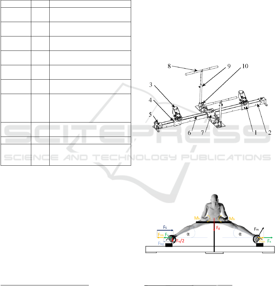
The outlined design consists of two sliding
mechanisms (1), running on U-Profiles (2) with
rotating foot straps (3), shown in Figure 1. The foot
straps can be set by locking pin at every 90°. The
sliders are connected with a circulating steel cable (4)
guide rollers are located at the outer end (5) of the U-
Profiles to ensure symmetric motion. The damper unit
of the braking system (6) is placed inside the U-
Profile. The trainer can be folded at the connection
plate (7) for easy transportation. The handles (8) are
height adjustable by lock pins (9) and are mounted in
injection moulded foldable plates (10).
Figure 1: Design of Flexibility trainer.
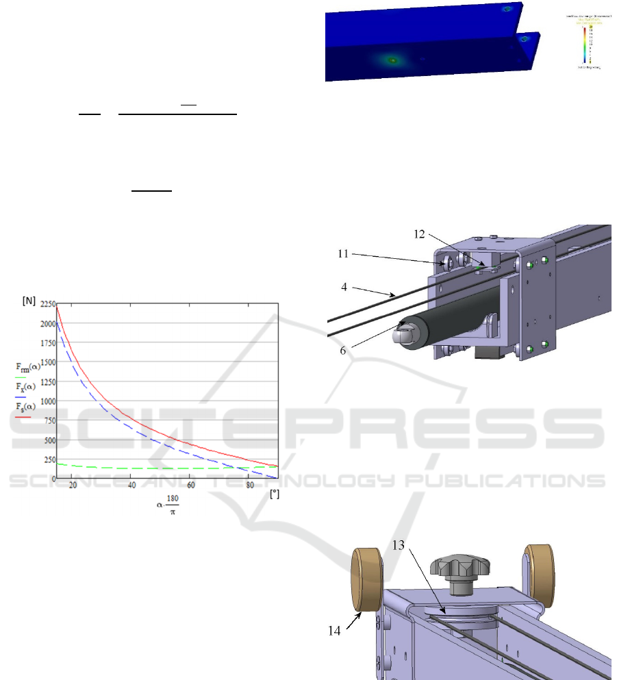
3.2 Calculations of External Loads
The expected user generated maximum loads are
calculated using maximum hip moment and the user’s
weight (see Figure 2).
Figure 2: Illustration of the force calculation method in
abduction
4
.
M
h
= Cumulated moment of hip joint
g = Gravitational acceleration
α = angle leg axis to floor
l
leg
= leg length
h
eff
= effective component of leg length
icSPORTS 2020 - 8th International Conference on Sport Sciences Research and Technology Support
24
For the calculation of F
rm
, the possible M
h
from an
Isokinetic test is approximately linearized (based on
the isokinetic hip abduction and adduction test of a
highly skilled Martial Artist, shown in Appendix A
and divided by effective height.
.
°
∗°
∗
(1)
The component F
x
of bodyweight F
g
is
∗∝
(2)
The resulting maximal force on the slider is the sum
of F
rm
and F
x
equal to approx. 2200 N at the minimal
possible α of 15°. Leg length is assumed 1 m and the
body weight up to 110 kg (see Figure 3).
Figure 3: Horizontal forces on slider depending on α.
This is also the assumed load for the braking system
and the other slider components. The selected damper
should work for speed up to 0.3 m/s at this load.
The force sensors should have a range from 100 N to
5000 N in pulling and pushing directions.
3.3 Components and Specific Loads
3.3.1 Rail System
The main part of the rail systems are the U-Profiles
100x80x10 mm. For weight reduction purpose the
chosen material is Polyamid. Maximal stress and
deformation is obtained via FEA (Finite Elements
Analysis; (Klein, 2012)). Maximum stress level of 25
MPa is located around the mounting holes as
expected and is well below the critical stress level
(Figure 4). The detailed model description is
available in Stummer (2016)
Figure 4: Von Mises stress on polyamid U-Profile
(Stummer, 2016).
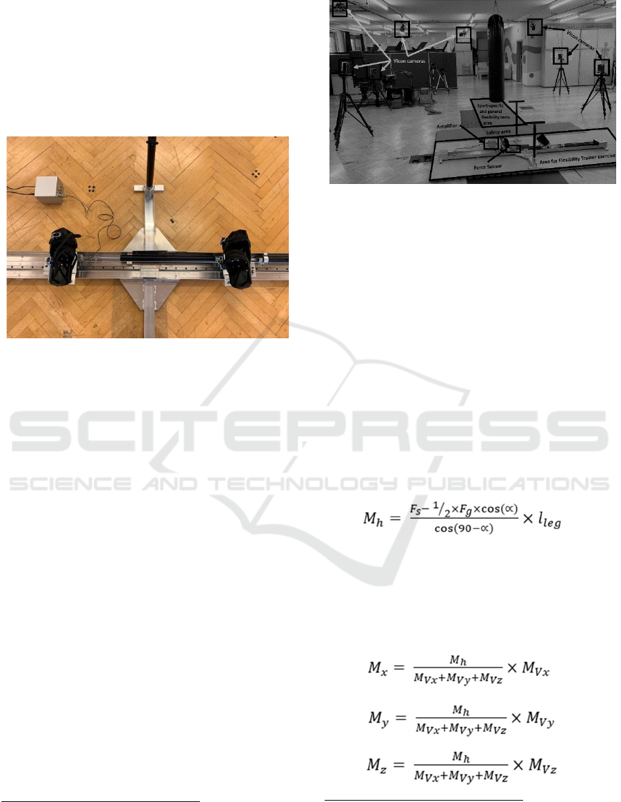
Inside the rail track two adjustable hydraulic brake
cylinders HB-40-500 and HB-40-600 (6) from
supplier ACE (Figure 5) are placed in series. The
maximum allowed force is 4000 N for the longer
600 mm cylinder.
Figure 5: Rail and slider system of one side.
The sliders are running on the U-Profile with SKF 635
ball bearings (11) to minimize the friction. Both
sliders are clamped to the steel cable (4) by sheet
metal (12) and M5 screws. For cable turn at the end
of the U-Profile guide pulleys 10/3 (13) from Ingo
Quirnbach Industrieservice are applied (Figure 6).
The two upstanding rollers 20K JGV 050-2 (14) from
Dematech are for transportation issues.
Figure 6: Rollers at the outer end of the U-Profile.
3.3.2 Sliders
The main frame of the slider is profiled from a metal
sheet of 3 mm thickness and connected to the braking
system by a detachable lock pin (15) as shown in
Figure 7. This enables dismantling for folding and
transportation.
The Flexibility Trainer: Feasibility Analysis, Prototype- and Test Station Development for a Sports Device for Hip-joint Flexibility and
Strength Enhancement
25
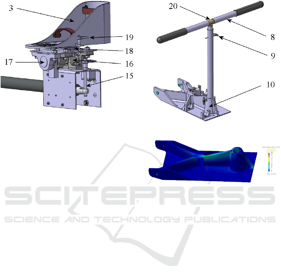
Figure 7: Slider with ankle tilt system and foot mount.
The ankle tilt mechanism, consisting of roller
bearings with housing SY 12 TF from SKF (16) and
rotational damper WRD-H-3015-C from Weforma
(17), is mounted on the slider frame. The torque of the
selected damper is adjustable from 2 to 14 Nm and
should reduce unintended ankle wobble.
A turntable (18) is placed between the foot mount
and the ankle tilt mechanism to allow the foot mount
rotation of 360° for spread training lateral and
longitudinal. It can be fixed every 90° by the lock pin
(19).
The foot mount (3) is manufactured by FDM
(Fused Deposition Modelling) for the prototype. For
serial production it will be injection moulded.
3.3.3 Holding Device
The choice of material for the tubes (8), of this
essential safety feature as shown in Figure 8, is CFRP
(carbon fibre reinforced plastic). Pre-ordered tubes
can be glued together with aluminium T-piece (20) to
form the handlebar. For ergonomic reasons, the
handlebar is height adjustable and fixed by a lock pin
(9).
The connection plate (10) is an injection moulded
part. The maximum stress is calculated at a horizontal
force of 300 N on the handlebar that leads to a
bending moment of 270 Nm at the tube mounting
dome. The FEM results show a maximum stress of 42
MPa at a single node (see Figure 9 and Stummer
(2016) for more details
).
Figure 8: Handlebar of CFRP tubes.
Figure 9: Von Mises stress on connection plate (Stummer,
2016).
The maximum stress in the ribs is less than 20 MPa
i.e. safely below critical stress.
3.3.4 Force Sensor
As stated in section 0, the expected maximum force
at the sensor is about 2200N per leg. Therefore, the
sensor should have a measuring range from 100N-
5000N. A U9c force sensor for forces up to 20kN has
been identified.
3.4 Changes for the Prototype
Due to manufacturing reasons some parts of the
design needed to be changed from the planned serial
manufacturing to prototyping (see Figure 10):
• Due to high costs, the injection moulded
mounting plates were changed to aluminium
plates.
• The minimum length of Polyamid U-Profile was
changed to aluminium profile.
icSPORTS 2020 - 8th International Conference on Sport Sciences Research and Technology Support
26
• As a consequence of the rail profile change the
sliders are now running on linear guide inside
the profile instead of the roller bearings outside.
• The foot mount changed from a 3D printed part
to mini skates available on the market.
• The holding devices are made of steel.
Figure 10: Manufactured prototype.
3.5 Proposed Test Setup
In order to comprehensively test the device and its
short-term effect on athletes, a testing setup utilizing
a Vicon® motion capturing system and a force sensor
within the device for measuring the force alongside
the rail, is proposed. The setup is specifically
designed to provide a detailed estimation of the hip
joint moments, to evaluate the athletes’ physical
strain during exercising in order to make propose
future training adaptations. In addition, the setup
includes a stage for practical measurements, such as
static flexibility tests and sport specific movements,
as well as a stage for device training.
3.5.1 System Setup
As stated above, the setup comprises both, one sport-
specific (e.g. Martial Arts) and one device-specific
movement analysis volume. The combined volume is
surrounded by 12 high-resolution infrared cameras,
specifically aimed to capture all markers, which are
attached to the athlete during the exercises, see Figure
11.
5
For Legend, see
Figure 2
6
Legend:
M
x
= Hip flexion moment
M
y
= Hip abduction moment
Figure 11: Proposed test setup for sport-specific and general
flexibility tests.
3.5.2 Hip-joint Moment Calculation
To calculate the hip joint moment with inclusion of
the external forces of the flexibility trainer, a
kinematic model of the hip joint centre, based on a
marker model and anthropometric data is required.
The Vicon® plug-in-gait model is applied (Vicon®,
2016). Hip joint angles can be obtained using the
static and dynamic plug-in-gait modelling function.
Centres of rotation are calculated by the functional
skeleton calibration.
Based on
Figure 2
, the cumulative hip moment (for leg
spreading) can be estimated by following inverse
calculation retrieved from the linear sensor force and
reduced by the gravity component
5
:
(3)
The cumulated hip-joint moment M
h
can then be
divided into the 3 movement direction components
6
(M
x
, M
y
, M
z
)
b
y splitting it in relation to the
calculated components from Vicon® (M
Vx
, M
Vy
,
M
Vz
), as the kinematic parameters, such as movemen
t
directions are the same with and without resistance.
(4)
(5)
(6)
M
z
= Hip rotation moment
M
Vx
= Vicon® calculated hip flexion moment
M
Vy
= Vicon® calculated hip abduction moment
M
Vz
= Vicon® calculated hip rotation moment
The Flexibility Trainer: Feasibility Analysis, Prototype- and Test Station Development for a Sports Device for Hip-joint Flexibility and
Strength Enhancement
27

3.6 Summary of Outcomes
The proposed final construction fulfils additional
framework conditions, such as weight and design
specifications, which will be necessary for a
commercially viable product, but are too expensive
for a prototype. Therefore, the design was optimized
in order to provide more safety and stability for
significantly lower costs. The testing setup is opted to
provide analysis possibilities for sport-specific and
general flexibility tests, as well as for the device
training analysis. Furthermore, to comprehensively
analyse the physical strain during the training, a
mathematical model for joint moment analysis was
used, based on the Vicon® model and the force sensor
data.
3.7 Limitations
The calculation model does currently solely comprise
the leg spreading motion because at the leg closing
motion the participant is estimated to reduce the
gravitational force by supporting his body weight on
the holding device. Therefore, to analyse the closing
moment, an additional sensor measuring Fg would be
needed, or the result would be given as a function
from 0-100% of body weight reduction. Furthermore,
marker position changes due to skin shifts might add
large error to the results of the separated moments.
Usability and effect sizes are not available yet.
4 CONCLUSIONS
The Flexibility Trainer prototype is expected to have
the potential to enhance the training of active and
passive flexibility, even more than with CRAC-PNF
methods, due to cumulated effects of combined
methodical approaches (isokinetic, full-ROM
strength training with CRAC), which might also last
longer. Furthermore, based on the tests and
component data sheets, the device should resist all
expected loads without damages and meet the
requirements. However, future studies are needed to
proof short- and long-term functionality.
REFERENCES
Alter, M. J. (2004). Science of flexibility: Human Kinetics.
Brown, L. E. (2000). Isokinetics in human performance:
Human Kinetics.
Csapo, R., Alegre, L. M., & Baron, R. (2011). Time kinetics
of acute changes in muscle architecture in response to
resistance exercise. Journal of Science and Medicine in
Sport, 14(3), 270-274. doi:10.1016/j.jsams.2011.
02.003
Franchi, M. V., Atherton, P. J., Reeves, N. D., Fluck, M.,
Williams, J., Mitchell, W. K., . . . Narici, M. V. (2014).
Architectural, functional and molecular responses to
concentric and eccentric loading in human skeletal
muscle. Acta Physiologica, 210(3), 642-654.
doi:10.1111/apha.12225\r10.1111/apha.12225.
Hölbling, D. (2016). EP000003269429A1. U. WIEN.
Hölbling, D., Preuschl, E., Hassmann, M., & Baca, A.
(2017). Kinematic analysis of the double side kick in
pointfighting , kickboxing. Journal of Sports Sciences,
35(4), 317-324. doi:10.1080/02640414.2016.1164333
Kent, M. (2006). The Oxford dictionary of sports science
and medicine: Oxford University Press, USA.
Klein, B. (2012). FEM: Grundlagen und Anwendungen der
Finite-Element-Methode im Maschinen-und
Fahrzeugbau: Springer-Verlag.
Moreira, P. V. S., & Gonzaga, A. C. d. O. (2012). The effect
of stretching on the health and performance: new
perspectives. Terapia Manual., 10(50), 148-157.
Pahl, G., & Beitz, W. (2013). Engineering design: a
systematic approach: Springer Science & Business
Media.
Roaas, A., & Andersson, G. B. (1982). Normal range of
motion of the hip, knee and ankle joints in male
subjects, 30–40 years of age. Acta Orthopaedica
Scandinavica, 53(2), 205-208.
Rowlands, A. V., Marginson, V. F., & Lee, J. (2003).
Chronic flexibility gains: Effect of isometric
contraction duration during proprioceptive
neuromuscular facilitation stretching techniques.
Research Quarterly for Exercise and Sport, 74(1), 47-
51. doi:10.1080/02701367.2003.10609063
Shan, G. (2005). Comparison of repetitive movements
between ballet dancers and martial artists: Risk
assessment of muscle overuse injuries and prevention
strategies. Research in Sports Medicine, 13(1), 63-76.
doi:10.1080/15438620590922103
Sharman, M. J., Cresswell, A. G., & Riek, S. (2006).
Proprioceptive neuromuscular facilitation stretching :
Mechanisms and clinical implications. Sports
Medicine, 36(11), 929-939.
Stummer, M. (2016). Beweglichkeitstrainer:
Weiterentwicklung des bestehenden Systems und
Konstruktion eines Prototyps. (Bachelor Thesis), TU
Wien
VDI2221. (2019). Design of technical products and systems
(Vol. Part 1): VDI-Gesellschaft Produkt- und
Prozessgestaltung
Vicon®. (2016). Plug-in Gait Reference Guide. In (pp. 95).
Retrieved from https://docs.vicon.com/display/Nexus
25/PDF+downloads+for+Vicon+Nexus?preview=/508
88706/50889377/Plug-in%20Gait%20Reference%20
Guide.pdf
Weber, A. E., Bedi, A., Tibor, L. M., Zaltz, I., & Larson, C.
M. (2015). The hyperflexible hip: managing hip pain in
the dancer and gymnast. Sports Health, 7(4), 346-358.
icSPORTS 2020 - 8th International Conference on Sport Sciences Research and Technology Support
28
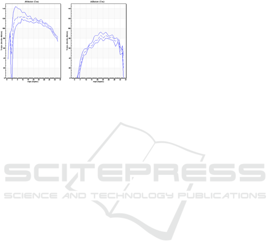
APPENDIX
Appendix A: Isokinetic hip joint adduction and abduction
tests of a highly skilled Martial Artist with a height of
1.82m and a weight of 78kg on a Humac® CSMI device.
The Flexibility Trainer: Feasibility Analysis, Prototype- and Test Station Development for a Sports Device for Hip-joint Flexibility and
Strength Enhancement
29
