
Design of Ship Course Controller based on Improved ADRC
Chunhao Yang
1, a
, Yonghua Zhou
1
1
College of electrical engineering, Guangxi University, Nanning 533000, China
Keywords: Ship Course Controller, Improved ADRC.
Abstract: There are many interference factors when ships are sailing at sea. Therefore, the ship's course control is very
important for its safe navigation. To solve this problem, a ship course controller with improved ADRC is
designed. The controller uses TD to extract the desired course signal. Real time estimation and compensation
of disturbance factors by ESO. Then the control law of the system is designed by using the backstepping
sliding mode variable structure control. Finally, the simulation experiment of the controller is carried out with
the simulation software of the real ship, the simulation results show the effectiveness of the controller.
1 INTRODUCTION
Course control is one of the most basic control
problems in ship navigation. However, due to the
large inertia and non-linear characteristics of the ship
itself, many challenges have been brought to the study
of the ship's course control method. Therefore, how
to eliminate the uncertain factors and control the
course quickly and accurately has become a research
hotspot (Li An, et,al, 2020).
In this paper, a ship course controller based on
improved ADRC is designed. The controller uses TD
(Tracking differentiator) to extract the desired course
signal. Real time estimation and compensation of
disturbance factors by ESO (Extended state
observer). Then, based on the traditional
backstepping method and sliding mode variable
structure control, the control law of ship course
controller is designed. The controller combines the
advantages of backstepping, sliding mode control and
ADRC (Mathematics, 2020). Therefore, it has fast
response speed and strong robustness.
2 SHIP NONLINEAR CONTROL
MODEL
In the presence of external interference, the nonlinear
operation model of the ship is as follows:
()
r
rfrbuw
(1)
In formula (1): ψ is the ship's course angle.r Is the
rotating head angular velocity of the ship.u is rudder
angle. f(r)is the internal interference caused by the
rotating head angular velocity. In addition, the
steering of the ship is completed by the steering gear.
Using inertia link to express the characteristics of the
steering gear, The expression of the inertia link of the
steering gear is as follows:
E
EE
TK
(2)
In formula (2): KE is the gain coefficient of the
steering gear, TE is the time constant.
3 DESIGN OF CONTROLLER
Ship course controller based on improved ADRC
technology consists of three parts. The following is a
detailed order of the three parts of the controller.
3.1 Design of TD
The main function of TD is to extract the desired
course signal and the differential value of the input
signal. For the above control system. According to
reference (Guo Siyu, et.al, 2020), the mathematical
expression of the tracking differentiator is as follows:
22
Yang, C. and Zhou, Y.
Design of Ship Course Controller based on Improved ADRC.
DOI: 10.5220/0010009500220024
In Proceedings of the International Symposium on Frontiers of Intelligent Transport System (FITS 2020), pages 22-24
ISBN: 978-989-758-465-7
Copyright
c
2020 by SCITEPRESS – Science and Technology Publications, Lda. All rights reserved

112
22 1 2
(1) () ()
(1) () ( (), ,,)
ddd
dd ddd
kkpk
k k pfhan k v p
(3)
In formula (3): p is the integration step,v is the
velocity factor, ψ
d
is the reference input signal, ψ
d1
is
an over signal of ψ
d
, ψ
d2
is the differential signal of
ψ
d
. fhan is the fastest comprehensive function. By
choosing appropriate integration step and velocity
factor, the tracking differentiator will be able to keep
up with the expected signal and the differential value
of the expected signal.
3.2 Design of ESO
ESO is the core of ADRC, it can estimate and
compensate the internal and external interference of
the whole system in real time. According to reference
(Yuanqing Wang, et.al, 2020), the following
expressions of linear extended state observer can be
obtained:
121
232
33
1
zzle
zzlebu
zle
ez
(4)
In formula (4): z= [z
1
z
2
z
3
]
T
is the estimated value
of the state variable ψ, r, h of the course control
system. L= [l
1
l
2
l
3
]
T
is the gain parameter of the ESO.
The estimation and compensation of system
disturbance can be realized by selecting the
appropriate L (Yuanqing Wang, et.al, 2020).
3.3 Design of Backstepping Sliding
Mode Controller
The expression of the error equation defining the
system is as follows:
1
2
d
d
e
err
(5)
In formula (5): r
d
is the virtual control quantity of
rotating head angular velocity. The mathematical
expression of r
d
is as follows:
11dd
rce
(6)
Take Lyapunov function as:
22
11
11
22
VeL
(7)
In formula (7):
d
L
L
r
, τ is the filter
coefficient of the filter [3]. Derivative formula (7), the
expression is as follows:
2
111 1112 1112
()VeeLLecee LL ceee
(8)
In order to make e
2
approach zero, sliding mode
control is introduced. The mathematical expression of
sliding mode surface is as follows:
22
h
se e
(9)
Take Lyapunov function as:
2
2
1
2
Vs
(10)
Derivative formula (12), the expression is as
follows:
112
2222222
1
()()
hhh
Vssse hee shee e
h
(11)
With the Lyapunov stability theory, the control
law of the system is obtained. The expression of the
control law is as follows:
2
212 3 3
0
11 1
( ( )sgn( ) ( )
t
h
d
ue ssdzr
bh b
(12)
4 SIMULATION EXPERIMENT
Taking the Yulong ship as the simulation object, The
parameters of ships are introduced in reference (Guo
Siyu, et.al, 2020). The selected controller parameters
are as follows: p=0.1, v=50, c
1
=0.05, h=1.25. The
simulation experiment is set as follows: the
simulation experiment duration is 200s, the expected
course signal is 30 degrees, the external interference
factor is wind force level 6, and the water flow rate is
1.3m/s. The simulation results are shown in Fig 1.
Design of Ship Course Controller based on Improved ADRC
23
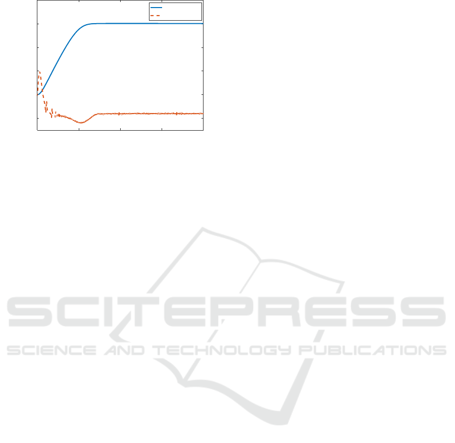
Figure 1: curve of ship course angle and rudder angle.
As can be seen from Fig 1, The system converges
in 70 seconds, no any overshoot. The curve change of
rudder angle is smooth. Finally stable at - 7 degrees
to resist the interference of external environmental
factors. The simulation results show the effectiveness
of the controller.
REFERENCES
Guo Siyu, Zhang Xiuguo, Zheng Yisong, Du And Yiquan.
An Autonomous Path Planning Model for Unmanned
Ships Based on Deep Reinforcement Learning [J].
Sensors (Basel, Switzerland), 2020, 20(2).
Li An, Ye Li, Jian Cao, Yanqing Jiang, Jiayu He, Haowei
Wu. Proximate time optimal for the heading control of
underactuated autonomous underwater vehicle with
input nonlinearities [J]. Applied Ocean Research, 2020,
95.
.Mathematics; New Findings Reported from Shanghai
Maritime University Describe Advances in
Mathematics (Finite-Time Speed Control of Marine
Diesel Engine Based on ADRC) [J]. Journal of
Mathematics,2020.
Yuanqing Wang, Guichen Zhang, Zhubing Shi, et al. Finite-
Time Speed Control of Marine Diesel Engine Based on
ADRC. 2020, 2020
0 50 100 150 200
t
(
s
)
-10
0
10
20
30
40
Course angle and rudder angle/°
Course angle
rudder angle
FITS 2020 - International Symposium on Frontiers of Intelligent Transport System
24
