
Analysis for Gerund Entity Anomalies in Data Modeling
Des Suryani
1
, Yudhi Arta
1
and Erdisna
2
1
Department of Informatics Engineering, Universitas Islam Riau, Pekanbaru, Indonesia
2
Department of Information System, Universitas Putra Indonesia, Padang, Indonesia
Keywords:
Anomaly, Data Redundancy, Data Inconsistency, Gerund Entity, Entity Relationship Diagram.
Abstract:
Data is the most important component of an information system development. Collected data that will be
used in future needs should be kept well to make it easy to inquire. The data stored in a database consists of
several groups of data relations. These relations should be connected through fields which are unique to the
relations linked. In designing database itself, it is very important to note how data is organized and stored to
minimize data redundancy. The tools used in depiction of the relationship between tables or entities are Entity
Relationship Diagram (ERD) that can have one to one, one to many and many to many relationships. Gerund
entity will be formed if the relationship between the entities is many to many. However, the new entity is still
a possible anomaly. The reanalysis is needed to be free of anomalies. Gerund entity that still has an anomaly
will form a new entity again, which in this case referred to as a sub gerund entity which is a derivative of
a gerund entity. The result of a good database design or free of anomalies will increase the optimization of
memory usage, consistency and integrity of data.
1 INTRODUCTION
Database is the most important component in the de-
velopment of Information Systems because it is a
place to accommodate and organize all data in the sys-
tem, so that it can be explored to compile information
in various forms (Sutedjo and Oetomo, 2002). The
data will be organized in such a way that there is no
unnecessary duplication, so that it can be processed
or explored quickly and easily to produce the infor-
mation needed. From several existing database mod-
eling, relational database modeling is still the most
used model by various Database Management Sys-
tem (DBMS) software. This is because it is easy to
manage data (Barioni et al., 2011; Stonebraker and
Moore, 1995).
Entity Relationship Diagram (ERD) is a model
diagram that is used as a representation of database
structure in which table information includes and the
existence of relationships between tables and the form
of the relation itself based on existing standard nota-
tions (Date, 1977). ERD is used to express the rela-
tionship between an entity or object in the form of a
table with another entity. In database design, logically
is done by transforming an ER diagram developed
during conceptual design into a relational database
scheme (Ramakrishnan and Gehrke, 2000; Gehrke
and Ramakrishnan, 2003).
Relationships that occur between entities have a
type of relationship: one-to-one (1: 1), one-to-many
(1: N) and many-to-many (M: N). Based on the many-
to-many relationship, it will form a new entity called
Gerund Entity or Associative Entity. But in this case,
the gerund entity still allows for irregularities (anoma-
lies) in storing data, namely the occurrence of du-
plication or waste of data. No writer has found a
study that examines the anomalies in the gerund en-
tity yet, so that further analysis needs to be done so
that the database created is really in accordance with
the objectives of the database itself including avoid-
ing or minimizing data redundancy, because the waste
of data will result in waste of memory usage and
can cause problems in the process of accessing data
such as data inconsistency, longer access times and
problems in data integrity (Gehrke and Ramakrish-
nan, 2003; Silberschatz et al., 1997).
2 DATA MODELLING
In describing ER diagrams, it takes the existence of
entities, attributes and relationships between entities.
Entity is a set of objects in the real world whose ex-
istence does not depend on others and has the same
146
Suryani, D., Arta, Y. and Erdisna, .
Analysis for Gerund Entity Anomalies in Data Modeling.
DOI: 10.5220/0009145601460150
In Proceedings of the Second International Conference on Science, Engineering and Technology (ICoSET 2019), pages 146-150
ISBN: 978-989-758-463-3
Copyright
c
2020 by SCITEPRESS – Science and Technology Publications, Lda. All rights reserved

property. Examples of objects in an entity that can be
uniquely identified are called entity occurrence. Enti-
ties can be something real, such as: Members, Films,
Office Branch or abstract (concepts), such as: Rental,
Registration, Role. (Kadir, 2000)
Transforming or mapping ER diagrams into rela-
tions is a mechanical process, in the sense that the
process has certain regularities. To transform from
the ER diagram to the relational scheme there are 3
(three) entities that need to be understood, namely
(Kroenke and Dolan, 1983; Silberschatz et al., 1997):
The document margins must be the following:
• Ordinary entities (regular entities) are entities that
are independent of their existence and generally
describe real objects in the real world. Ordinary
entities are often also called strong entities de-
picted with four single-striped rectangles.
• Weak entities (week entity) are entities whose ex-
istence depends on other entities (usually strong
entities). Weak entities are represented by four
double-striped rectangles.
• Associative entities (associative entities) or
gerund entities are generally formed from many to
many relationships between other entities. Asso-
ciative entities are generally represented by rect-
angles with parallelograms in them.
Types of relations can be classified as follows:
• one-to-one (1: 1)
• one-to-many (1: M)
• many-to-many (M: N)
Gerund Entity or Associative Entity is formed
from many to many relationships. Example: Student
entity with the subject matter, Customer entity with
the Goods entity and so on.
In logical database design, it can be done by:
• Applying Normalization to a known table struc-
ture.
• Directly create the Entity-Relationship (ER
model) model.
Logical data model is a source of physical de-
sign information. This model provides designers with
a vehicle for consideration in designing an efficient
database.
Physical database design is the process of produc-
ing a description of database implementation on sec-
ondary storage, describing storage structures and ac-
cessing methods to improve access effectiveness. At
this stage, physical design is intended for a particular
DBMS. Physical level database design has been asso-
ciated with database management systems and plat-
forms where the database is implemented (Connolly
and Begg, 2005).
Well-organized data can produce good informa-
tion Organizing data to prevent unnecessary duplica-
tion. Data that is organized and correlated each other
called as a database, whereas to manage and orga-
nize databases that are built in a system, a database
management is called a database management system
(DBMS). DBMS is software that will determine how
data is organized, stored, modified, retrieved, regu-
lated data security mechanisms, and mechanisms for
sharing data together (Date, 1983).
2.1 Role of Normalization in Database
Design
Normalization is a formal technique that can be used
in database design. The main purpose of normaliza-
tion is to identify the suitability of relationships that
support data to meet the needs of a particular com-
pany or institution. The role of normalization in this
case is in the use of bottom-up approaches and vali-
dation techniques. The validation technique is used to
check whether the relation structure produced by the
ER model is good or not. For more details, it can be
shown in figure 1.
Figure 1: Role of normalization in database design.
In Figure 1 it can be seen that the data source con-
sists of users, specifications of various user require-
ments, various forms or reports, data dictionary and
enterprise data models. Then there is the top-down
and bottom-up approach where the approach will re-
sult in the design of relations, then the role of normal-
ization on bottom up and validation techniques (In-
drajani, 2011).
Analysis for Gerund Entity Anomalies in Data Modeling
147
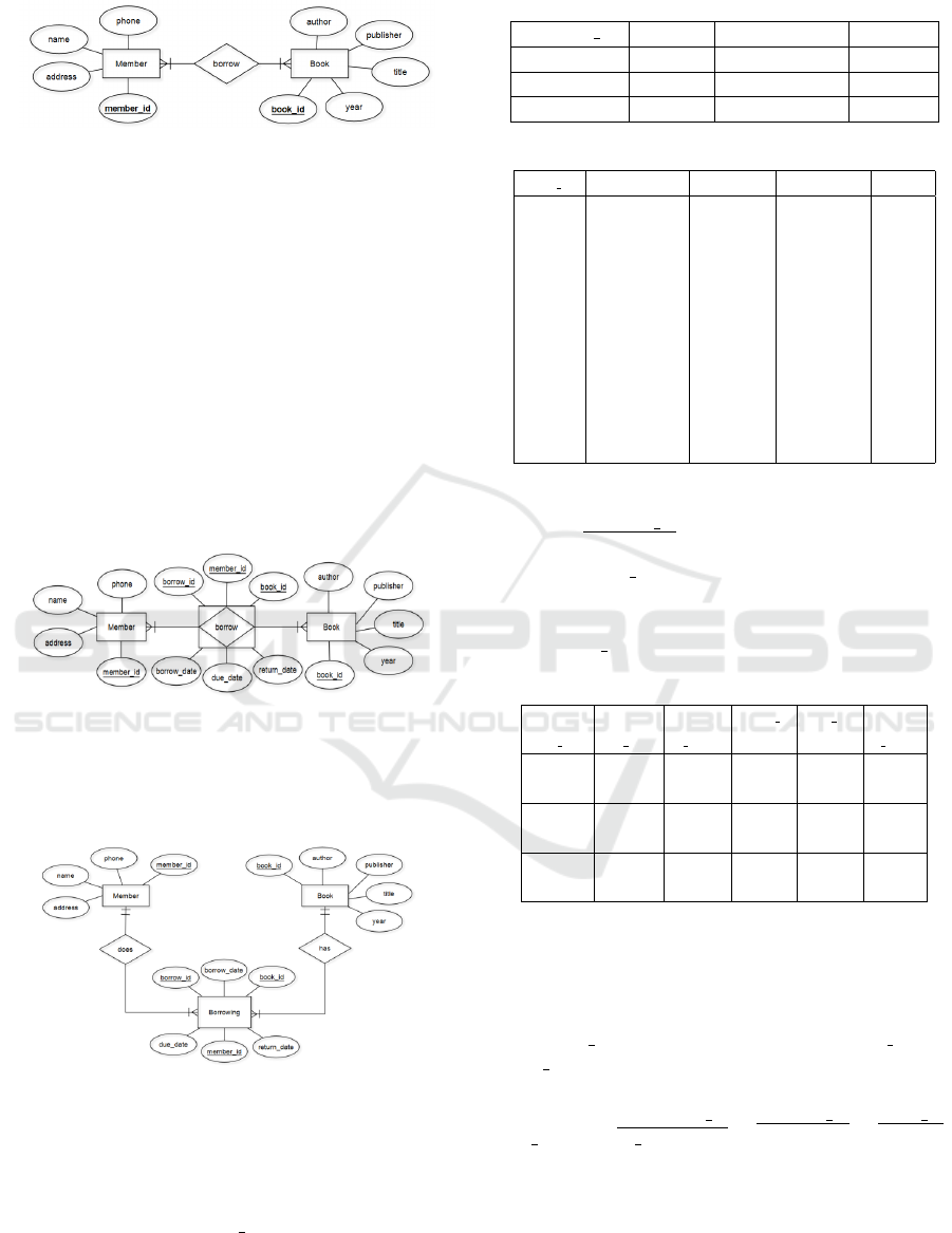
Figure 2: The relationship of many to many between mem-
ber entity and book entity.
3 RESULT AND DISCUSSION
3.1 Entity Relationship Model
In relational data modelling using the ER diagram can
be described in figure 2.
If the entities relationship described as many to
many, then it will make a new entity called Gerund
Entity or Associative Entity. The field key which con-
nected each entities should be there in the new entity.
Then, it continues by more relevant attributes added.
It can be seen in figure 3.
Figure 3: Gerund entity from the relationship of book entity
to the member entity.
The diagram in figure 3 can be described more de-
tail in figure 4.
Figure 4: New entity formed (gerund entity).
Based on diagram in figure 4, can be transformed
into tables/relations by sample data shown in table 1
to table 3.
The Member relation in the table 1 can be save
member data with member id as primary key. The
relation doest not have redudancy data.
The member relation has the form:
Table 1: Member Relation
member id name address phone
1001 John Sudirman 10 654534
1002 Dannis Dt. Setia 15 742345
1003 Betty M.Yamin 12 653421
Table 2: Book Relation
book id title Author Publisher year
C-001
Concepts of
Database
Management
Philip
J.Pratt,
Joseph J
Adamski
Course
Technology
2012
C-002
Principles of
Distributed
Systems
M. Tamer
Ozsu,
Patrick
Valduriez
Springer 2015
A-002
Fundamental
Accounting
Principles
John J.
Wild, Ken
W.Shaw
Mc Grow
Hill
2015
Member (member id, name, address, phone)
The Book relation in the table 1 can be save book
data with book id as primary key. The relation also
does not have redudancy data.
The book relation has the form:
Book (book id, title, author, publisher, year)
Table 3: Borrowing Relation
borrowi
ng id
membe
r id
borrow
date
book i
d
due da
te
return
date
19001 1001
05/02/
2019
C-001
05/09/
2019
05/08/
2019
19001 1001
05/02/
2019
C-002
05/10/
2019
06/12/
2019
19004 1003
06/10/
2019
C-002
06/15/
2019
06/10/
2019
Cardinality relation between member and book re-
lation is many to many so it creates the new table as
gerund entity. In this case is called borrowing rela-
tion (shown in the table 3). Borrowing relation has
borrowing id as primary key while member id and
book id is a foreign key.
The borrowing relation has the form:
Borrowing (borrowing id, member id, book id,
due date, return date)
3.2 Analysis Anomalies of Gerund
Entity
Analysis of anomalies in the Borrowing relation by
using normalization technique.
ICoSET 2019 - The Second International Conference on Science, Engineering and Technology
148
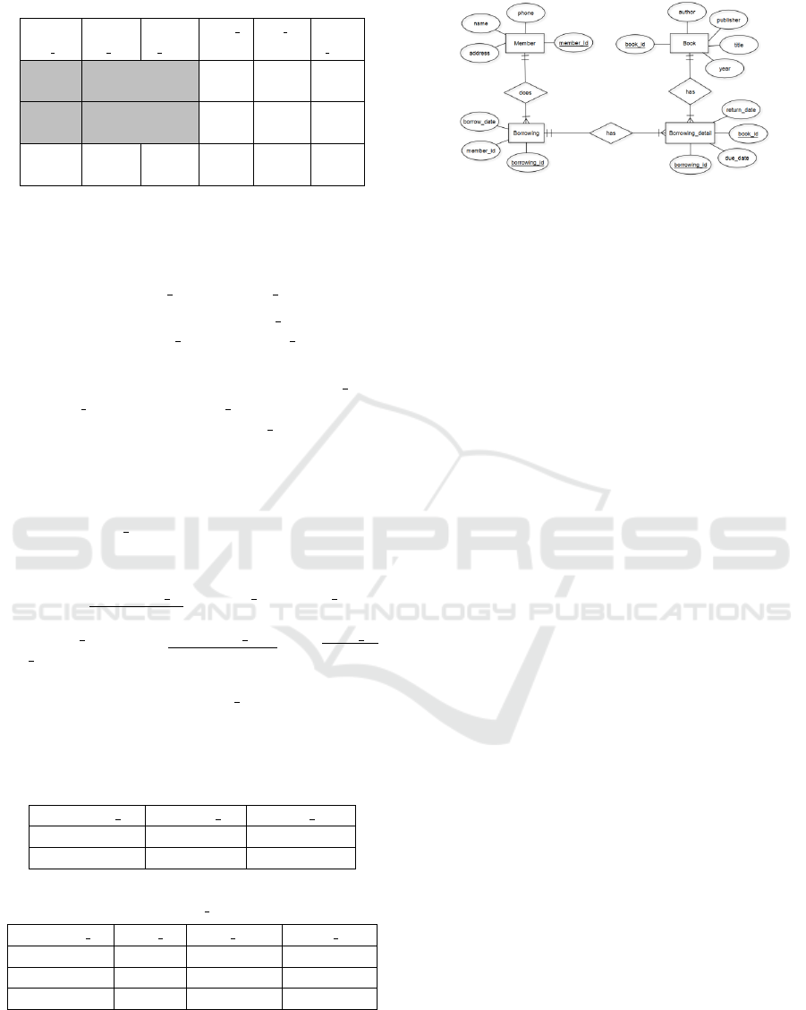
Table 4: Borrowing Relation
borrowi
ng id
membe
r id
borrow
date
book i
d
due da
te
return
date
19001 1001
05/02/
2019
C-001
05/09/
2019
05/08/
2019
19001 1001
05/02/
2019
C-002
05/10/
2019
06/12/
2019
19004 1003
06/10/
2019
C-002
06/15/
2019
06/10/
2019
In the Borrowing table as gerund entity. This ta-
ble has some anomalies. It can be seen a member
borrows 2 books at 05/02/2019. In here contain data
redundancy in member id and borrow date.
• To insert the book of borrowing id 19004, we
must enter member id and borrow date repeat-
edly.
• If we want to change the value of member id or
borrow date for borrowing id ‘19001’, we must
update the rows of the borrowing id. If this mod-
ification is not carried out on all the appropriate
rows of the Borrowing relations, the database will
become inconsistent. So that, the borrowing rela-
tion should be separated as a new table that called
is Borrowing Detail relation.
The resulting normalization relation have the form:
Borrowing (borrowing id, member id, borrow date)
Borrowing Detail (borrowing date, book id,
due date, return date)
The Borrowing and Borrowing Detail relations are
shown in Table 5 and Table 6. The result of Gerund
Entity analysis from Borrowing relation can be shown
ER model in Figure 5.
Table 5: Borrowing Relation
borrowing id member id borrow date
19001 1001 05/02/2019
19004 1003 06/10/2019
Table 6: Borrowing Detail Relation
borrowing id book id due date return date
19001 C-001 05/09/2019 05/08/2019
19001 C-002 05/10/2019 06/12/2019
19004 C-002 06/15/2019 06/10/2019
The establishment of a new entity from the gerund
entity above will minimize or eliminate data redun-
dant that can improve optimization of memory usage,
consistency and data integrity.
Figure 5: ERD from analysis of Gerund Entity.
4 CONCLUSIONS
Based on the results of the analysis that has been car-
ried out it can be concluded as follows:
In the gerund entity is still possible for an anomaly
to occur, so that it will create a new entity again as
a derivative of the gerund entity which in this case
the author called the sub gerund entity. In the gerund
entity, it is necessary to provide a connecting field to
the unique sub gerund entity. The establishment of
a new entity from the gerund entity will minimize or
not even redundant the data so that it can improve op-
timization of memory usage, consistency and data in-
tegrity. For complex databases, anomalous analysis
of sub gerund entities can still be continued to ensure
that the resulting relations are free from anomalies.
ACKNOWLEDGEMENTS
This research supported by Universitas Islam Riau.
Thank you very much for supported by UIR.
REFERENCES
Barioni, M. C. N., dos Santos Kaster, D., Razente, H. L.,
Traina, A. J., and J
´
unior, C. T. (2011). Querying mul-
timedia data by similarity in relational dbms. In Ad-
vanced database query systems: techniques, applica-
tions and technologies, pages 323–359. IGI Global.
Connolly, T. M. and Begg, C. E. (2005). Database systems:
a practical approach to design, implementation, and
management. Pearson Education.
Date, C. J. (1977). An introduction to database systems (Vol.
1). Pearson Education India.
Date, C. J. (1983). n introduction to database systems, Vol.
II. Reading, Mass.
Gehrke, J. and Ramakrishnan, R. (2003). Database man-
agement systems. McGraw-Hill.
Indrajani, S. M. (2011). Pengantar dan Sistem Basis Data.
Jakarta: PT Elex Media Komputindo.
Analysis for Gerund Entity Anomalies in Data Modeling
149

Kadir, A. (2000). Konsep Dan Tuntunan Praktis Basis Data,
Ed. 1, Cet. 2. ANDI, Yogyakarta.
Kroenke, D. M. and Dolan, K. (1983). Database Process-
ing: Fundamentals, Design. Implementation. author.
Ramakrishnan, R. and Gehrke, J. (2000). Database man-
agement systems. McGraw Hill.
Silberschatz, A., Korth, H. F., and Sudarshan, S. (1997).
Database system concepts (Vol. 4). McGraw-Hill New
York.
Stonebraker, M. and Moore, D. (1995). Object-relational
DBMS-the next wave. Informix Software (Now Part
of the IBM Corp. Family), Menlo Park, CA, 14.
Sutedjo, B. and Oetomo, D. (2002). Perencanaan dan Pem-
bangunan Sistem Informasi. Yogyakarta: Andi Offset.
ICoSET 2019 - The Second International Conference on Science, Engineering and Technology
150
