
A Generalized Odometry for Implementation of Simultaneous
Localization and Mapping for Mobile Robots
Kethavath Raj Kumar
Intelligent Systems and Robotics Division, Centre for Artificial Intelligence and Robotics, India
Keywords:
SLAM, Odometry, LiDAR, IMU, Particle Filter, Mobile Robot.
Abstract:
This paper proposes a novel method for calculation of generalized Odometry using velocities from Light
Detection and Ranging (LiDAR) and Inertial Measurement Unit (IMU), discounting velocities from motor
encoder values. Further, the estimated velocities are used for the calculation of Odometry using rigid body
Newtonian equations. The generalized Odometry and laser scans are used for implementation of the particle
filter Simultaneous Localization and Mapping (SLAM) algorithm. This method overcomes errors due to slip-
pages in mobile robots. The outputs of SLAM maps are experimentally validated in both straight and curved
trajectories with reference to ground truth maps. SLAM results obtained from the proposed method Odom-
etry is better than the only LiDAR, IMU and Encoder Odometry in an indoor environment for autonomous
navigation of mobile robots.
1 INTRODUCTION
Mobile robots are used in various applications such
as surveillance, military, mine detection, search and
rescue operations etc. Simultaneous Localization and
Mapping (SLAM) is used for navigating the mobile
robot autonomously in indoor environments. Indoor
SLAM systems are based on vision and LiDAR sen-
sors. However, visual SLAM methods are sensitive to
illumination conditions (Mur-Artal et al., 2015; Engel
et al., 2014). LiDAR SLAM methods overcome draw-
back of former methods, which can be considered for
mobile robots. These algorithms are based on scan-
to-scan and scan-to-map matching techniques.
A scan-to-scan matching algorithms takes laser
scan as input to compute the SLAM (Sokolov et al.,
2017; Olson, 2015). However, these techniques
quickly accumulate error over a time period. These
accumulated error from scan-to-scan match tech-
niques are corrected through scan-to-map algorithm
(Olson, 2009). But this algorithm does not pro-
vide loop closure detection. Two other common ap-
proaches for solving accumulation errors are graph
based and particle filters SLAM algorithms. Graph
based SLAM algorithm takes input as laser scans
and Odometry (Kohlbrecher et al., 2011). However,
this method expects accurate Odometry like GPS-
INS, which is not available for indoor mobile robot
navigation. Particle filters are most popular among
bayes filters (Konolige et al., 2010). It uses a laser
scans and Odometry measurements for computation
of SLAM. This method performs well even with ap-
proximate Odometry in indoor environments (Thrun
et al., 2005). However, this method fails if no Odom-
etry is available.
A novel method is proposed for calculation of
Odometry using LiDAR and IMU velocities. This is
a generalized Odometry because it is independent of
the mobile robot kinematics. Further, the generalized
Odometry and laser scans are used for the implemen-
tation of the particle filter SLAM algorithm on mobile
robot in an indoor environment.
In this paper, Section-II describes the related
work, Section-III describes the proposed method for
calculation of Odometry, Section-IV describes the test
platform, Section-V describes the SLAM implemen-
tation, Section-VI describes the results and discus-
sion, and Section-VII describes the conclusion.
2 RELATED WORK
M. Sokolov et al. have presented ROS-based visual
and LiDAR Odometry analysis for crawler-type robot
in indoor small scale with minimal turnings (Sokolov
et al., 2017). They found that the trajectory generated
from LiDAR Odometry was closer to ground truth
as compared to visual Odometry in spite of doing
Raj Kumar, K.
A Generalized Odometry for Implementation of Simultaneous Localization and Mapping for Mobile Robots.
DOI: 10.5220/0007922603950400
In Proceedings of the 16th Inter national Conference on Informatics in Control, Automation and Robotics (ICINCO 2019), pages 395-400
ISBN: 978-989-758-380-3
Copyright
c
2019 by SCITEPRESS – Science and Technology Publications, Lda. All rights reserved
395

camera stabilization. However, they have not shown
the results in large scale environments and different
curved trajectories of the robot.
E. Olson et.al presented a many-to-many multi-
resolution scan matching algorithm (Olson, 2015),
E. B. Olson et.al presented the real-time correlative
scan matching for the calculation of relative poses
and associated covariance matrix estimation (Olson,
2009). Stefan Kohlbrecher et. al. developed a flexi-
ble, fast, low-compute and scalable SLAM algorithm
(Kohlbrecher et al., 2011). This approach uses the
Gauss-Newton method to find local optima on a lin-
early interpolated map using scan-to-map matching
approach. Scan-to-map matching helps in reducing
the accumulation error, provided sufficiently high up-
date rate from LiDAR. However, this method ignores
the loop closure capability for creating the maps.
K.Konolige et. al. proposed an efficient and open
source algorithm called kartoSLAM (Konolige et al.,
2010), for solving the nonlinear optimization using
sparse pose adjustment (SPA) for 2D pose graphs.
Since they all use scan matching algorithms these
techniques quickly accumulate error over a time pe-
riod.
Thrun et al. presented the filter convergence and
inconsistency issues for the implementation of KF
and EKF based SLAM algorithms as mentioned in
(Thrun et al., 2005; Huang and Dissanayake, 2007).
Giorgio Grisetti et al. developed a particle filter based
SLAM technique. It uses laser scan and Odometry
measurements to compute the SLAM in indoor envi-
ronments. This method works better, when provided
with approximated Odometry along with laser scans.
The details and theoretical formulations of the algo-
rithm are given in (Grisettiyz et al., 2005; Grisetti
et al., 2007).
Tianmiao Wang et al. presented the skid steered
wheeled mobile robot Odometry using LiDAR (Wang
et al., 2015). However, they did not implement the
SLAM. Martinez et al. presented the solving kinemat-
ics model using motor encoder values (Martinez et al.,
2004; Mart
´
ınez et al., 2005). R.Gonzalez et. al. pre-
sented a mobile robot trajectory under slip conditions,
Further they fused this data using indirect kalman fil-
ter (Gonzalez et al., 2009). G. Yamauchi et. al pre-
sented the velocity based kinematic model using mo-
tor encoder velocities (Yamauchi et al., 2017). How-
ever, these methods cause the slippage during robot
motion.
For implementation of SLAM algorithm ROS
software stack is used as a middleware for the mo-
bile robot, which is developed by M. Quigley et.al.
(Quigley et al., 2009). It is open source software
widely used in robotics research.
3 PROPOSED METHOD
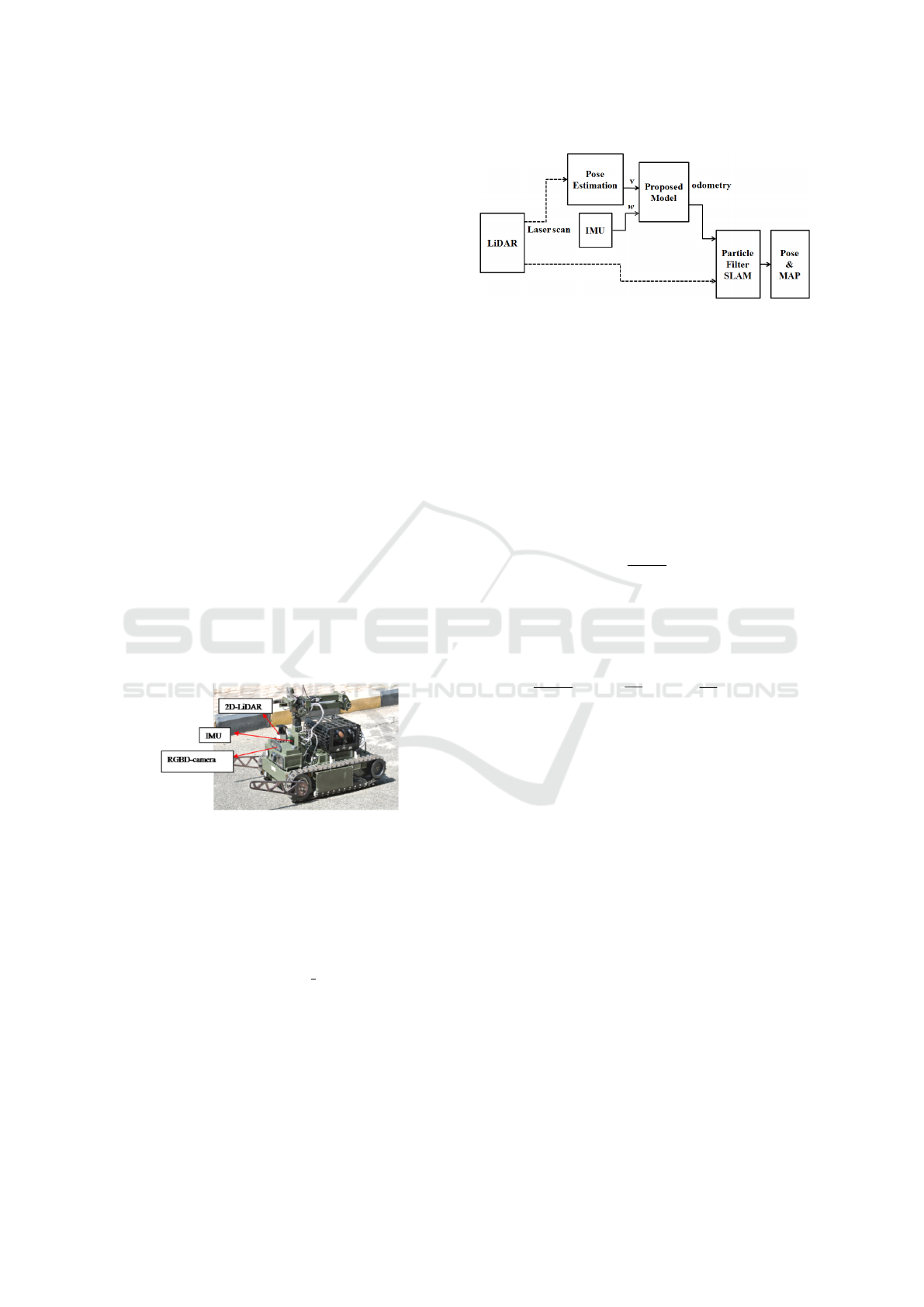
For calculation of generalized Odometry a novel
method is proposed as shown in Figure 2.
3.1 Estimation of Velocities from
LiDAR and IMU
3.1.1 The Linear Velocity Estimated from
LiDAR
For estimation of linear velocity from LiDAR, The
pose estimation method is adopted from Stefan
Kohlbrecher et al.(Kohlbrecher et al., 2011). The pose
vector p
G
represented as
p
G
=
t
x
g
y
g
θ
g
(1)
The linear velocities are estimated from above
pose estimation is represented as
v
x
=
dx
g
dt
(2)
v
y
=
dy
g
dt
(3)
where v
x
and v
y
are the longitudinal and lateral
velocities. The magnitude of the velocity is given in
equation 4, is assumed to be along the heading of the
vehicle
V =
q
v
2
x
+ v
2
y
(4)
3.1.2 The Angular Velocity from IMU
The IMU sensor is used for calculation of angular
velocity from gyroscope sensor. IMU is a combina-
tion of accelerometer, gyroscope and magnetometer.
It provides the raw accelerations, angular rates and
fused orientations.
3.2 Odometry Calculation using Rigid
Body Newtonian Equations
Given a velocities (linear and angular) of a rigid body
the pose is calculated using Newtonian equations de-
fined as
∆x = V ∆t cos θ (5)
∆y = V ∆t sin θ (6)
∆θ = w∆t (7)
ICINCO 2019 - 16th International Conference on Informatics in Control, Automation and Robotics
396
where v and w represent the linear and angular ve-
locities of the rigid body and ∆t is the sampling in-
terval. ∆x, ∆y and ∆θ are the distance travelled in the
last sampling interval.
The pose vector p of the mobile robot defined as
p =
x
y
θ
(8)
where x and y represent the position and θ is the
orientation of the mobile robot. Considering the in-
cremental motion of the robot ∆x, ∆y and ∆θ, the up-
dated pose p
0
of the robot can be represented as
p
0
=
x
y
θ
+
∆x
∆y
∆θ
(9)
4 TEST PLATFORM
For implementation of the particle filter SLAM algo-
rithm using generalized Odometry, the tracked mobile
robot is considered for experiments as shown in Fig-
ure 1. The tracked robot is integrated with IMU and
2D-LiDAR sensors. The robot consists of embedded
pc (IPC2 intel core i7 with 16 GB RAM and 1.4 GHz
dual core) with operating system Ubuntu 16.04 Linux
distribution along with the ROS Kinetic framework.
Figure 1: The tracked mobile robot used for the experi-
ments.
5 SLAM IMPLEMENTATION
5.1 Particle Filter SLAM
Particle filter based ROS slam gmapping algorithm
developed by Giorgio Grisetti et al. (Grisettiyz et al.,
2005; Grisetti et al., 2007) is used for implementation
of SLAM algorithm.
The generalized Odometry and laser scan mea-
surements are provided as input to the particle filter
based SLAM implementation as shown in block dia-
gram Figure 2.
Figure 2: Block Diagram of Proposed Method for calcula-
tion of Generalized Odometry and SLAM.
5.2 Particle Filter Formulation
Given a set of observations from LiDAR and mea-
surements from Odometry defined as
Z
1:t
= Z
1
, Z
2
, .....Z
t
(10)
U
2:t
= U
1
, U
2
, .....U
t
(11)
Calculating the posterior P with M grid map using
equations and the trajectory of the robot defined as
P
X
1:t
,M
Z
1:t
,U
2:t
, (12)
X
1:t
= X
1
, X
2
, .....X
t
(13)
The Rao-Blackwellized particle filter for SLAM
makes use of the following factorization
P
X
1:t
,M
Z
1:t
,U
2:t
= P
M
X
1:t
Z
1:t
P
X
1:t
Z
1:t
U
1:t
(14)
This factorization allows us to estimate the trajec-
tory of the robot and then computes the map given
a trajectory. Since the map strongly depends on the
pose estimation of the robot, this approach offers an
efficient computation.
6 RESULTS AND DISCUSSION
To conduct our SLAM experiments we considered the
following maps as ground truth as shown in Figures
3,4,5.
6.1 SLAM using only LiDAR Odometry
In this experiment, the main objective was to verify
only LiDAR based SLAM algorithm to create com-
plete corridor of the indoor environment as shown in
Figure 3.
Only LiDAR based SLAM algorithm fails to cre-
ate the corridor, due to failure of loop closure in Li-
DAR Odometry as it created two corridors instead of
one as shown in Figure 6.
A Generalized Odometry for Implementation of Simultaneous Localization and Mapping for Mobile Robots
397
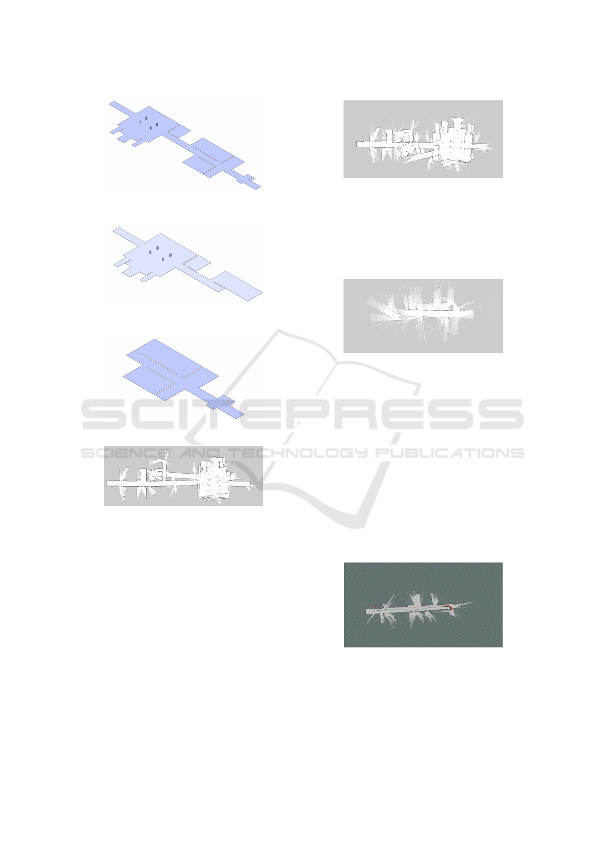
Figure 3: Ground Truth of Foyer with four pillars connected
with corridor.
Figure 4: Ground Truth of Foyer with four pillars connected
with half corridor.
Figure 5: Ground Truth of corridor.
Figure 6: Only LiDAR Odometry based SLAM Algorithm.
6.2 SLAM using Encoder Odometry
In this experiment, the main objective was to verify
the SLAM algorithm using Encoder Odometry from
tracked robot with respect to the ground truth map as
shown in Figure 3. Encoder Odometry in a tracked
robot is not accurate because of the amount of slip-
page in turns which causes the failure of SLAM as
shown in Figure 7.
From this experiment we conclude that for tracked
robot, encoder Odometry failed to create the map.
6.3 SLAM using IMU Odometry
In this experiment, the main objective was to ver-
ify the SLAM algorithm using IMU Odonetry from
tracked robot with respect to the ground truth map as
Figure 7: Encoder Odometry and LiDAR SLAM Algo-
rithm.
shown in Figure 5. For calculation of IMU Odometry,
the accelerations are integrated twice for calculation
of positions, which causes drift in the position over a
time period. The created map using IMU Odometry
fails to create corridor as shown in Figure 8.
Figure 8: IMU Odometry and LiDAR based SLAM.
6.4 SLAM using Generalized Odometry
To verify the particle filter SLAM using generalized
Odometry multiple experiments are carried out in an
indoor environment using tracked robot.
Experiment-1:
In the first experiment the robot is moved along
a path composed of a turn and straight trajectory. The
main objective is to verify the particle filter SLAM in
a predefined path using generalized Odometry with
reference to the ground truth map as shown in Figure
5.
Figure 9: Rviz SLAM pose(green) using generalized
Odometry(red) in straight corridor.
The tracked robot is placed in a corridor initially
the robot is turned and travelled in a straight trajec-
tory as shown in rviz output Figure 9 to compute the
SLAM in a corridor. The red color indicates the pose
from generalized Odometry and green color is the
ICINCO 2019 - 16th International Conference on Informatics in Control, Automation and Robotics
398
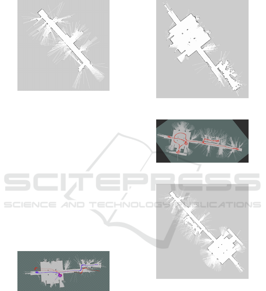
Figure 10: Map generated using generalized Odometry in
straight corridor.
output pose from Particle Filer SLAM after correction
using LiDAR. The output map is shown in Figure 10.
Experiment-2:
In the second experiment, the main objective is
to verify the particle filter SLAM algorithm in differ-
ent curved and straight trajectories using generalized
Odometry with reference to ground truth map as
shown in Figure 4.
Initially, the tracked robot is placed in a foyer of 4
pillars connected with two corridors and two rooms.
The robot travelled through different straight trajec-
tories and curved trajectories like on the spot,turn of
180 degree and two turns of 90 degree rotations to
compute the SLAM as shown in rviz output Figure
11.
After travelling through different straight and
curved trajectories, the robot has created the map as
shown in Figure 12.
Figure 11: Rviz SLAM pose(green) using generalized
Odometry(red) in straight and curved paths.
Experiment-3:
In the third experiment, the main objective was
to create a complete corridor map as shown in Figure
3 using generalized Odometry.
The tracked robot created an complete corridor
map using generalized Odometry which was com-
pletely matching with ground truth map as shown in
Figure 12: Map generated using generalized Odometry in
straight and curved paths.
Figure 13: Rviz SLAM pose(green) on entire floor using
generalized Odometry(red).
Figure 14: Map generated on entire floor using generalized
Odometry.
rviz Figure 13. The output of the trajectory is shown
in red color. The output of the map is shown in Figure
14.
7 CONCLUSION
The generalized Odometry using LiDAR and IMU
was considered instead of only LiDAR, Encoder and
IMU Odometry for implementation of the particle fil-
A Generalized Odometry for Implementation of Simultaneous Localization and Mapping for Mobile Robots
399

ter SLAM algorithm along with laser scans on tracked
mobile robot in an indoor environment. The output
SLAM maps using generalized Odometry in all the
three cases was matching with respect to ground truth
maps. These maps can be used for the autonomous
navigation in indoor environments. This method over-
comes errors due to slippages, because motor encoder
velocities are discounted for calculation of Odome-
try. Since this method is independent of mobile robot
kinematics, it can be experimented on other mobile
robots also.
ACKNOWLEDGEMENTS
The author thanks the Director, CAIR for granting
permission to publish the results of this research.
REFERENCES
Engel, J., Sch
¨
ops, T., and Cremers, D. (2014). LSD-SLAM:
Large-scale direct monocular SLAM. In European
Conference on Computer Vision (ECCV).
Gonzalez, R., Rodriguez, F., Guzm
´
an, J., and Berenguel,
M. (2009). Localization and control of tracked mobile
robots under slip conditions. pages 1 – 6.
Grisetti, G., Stachniss, C., and Burgard, W. (2007).
Improved techniques for grid mapping with rao-
blackwellized particle filters. IEEE Transactions on
Robotics, 23(1):34–46.
Grisettiyz, G., Stachniss, C., and Burgard, W. (2005). Im-
proving grid-based slam with rao-blackwellized parti-
cle filters by adaptive proposals and selective resam-
pling. In Proceedings of the 2005 IEEE International
Conference on Robotics and Automation, pages 2432–
2437.
Huang, S. and Dissanayake, G. (2007). Convergence and
consistency analysis for extended kalman filter based
slam. IEEE Transactions on Robotics, 23(5):1036–
1049.
Kohlbrecher, S., Stryk, O. V., Darmstadt, T. U., Meyer, J.,
and Klingauf, U. (2011). A flexible and scalable slam
system with full 3d motion estimation. In in Inter-
national Symposium on Safety, Security, and Rescue
Robotics. IEEE.
Konolige, K., Grisetti, G., K
¨
ummerle, R., Burgard, W.,
Limketkai, B., and Vincent, R. (2010). Efficient sparse
pose adjustment for 2d mapping. In 2010 IEEE/RSJ
International Conference on Intelligent Robots and
Systems, pages 22–29.
Martinez, J. L., Mandow, A., Morales, J., Garcia-Cerezo,
A., and Pedraza, S. (2004). Kinematic modelling
of tracked vehicles by experimental identification.
In 2004 IEEE/RSJ International Conference on In-
telligent Robots and Systems (IROS) (IEEE Cat.
No.04CH37566), volume 2, pages 1487–1492 vol.2.
Mart
´
ınez, J. L., Mandow, A., Morales, J., Pedraza, S., and
Garc
´
ıa-Cerezo, A. (2005). Approximating kinematics
for tracked mobile robots. The International Journal
of Robotics Research, 24(10):867–878.
Mur-Artal, R., Montiel, J. M. M., and Tard
´
os, J. D. (2015).
Orb-slam: A versatile and accurate monocular slam
system. IEEE Transactions on Robotics, 31(5):1147–
1163.
Olson, E. (2009). Real-time correlative scan matching.
pages 4387 – 4393.
Olson, E. (2015). M3rsm: Many-to-many multi-resolution
scan matching. 2015 IEEE International Conference
on Robotics and Automation (ICRA), pages 5815–
5821.
Quigley, M., Conley, K., Gerkey, B. P., Faust, J., Foote, T.,
Leibs, J., Wheeler, R., and Ng, A. Y. (2009). Ros: an
open-source robot operating system. In ICRA Work-
shop on Open Source Software.
Sokolov, M., Bulichev, O., and Afanasyev, I. (2017). Anal-
ysis of ros-based visual and lidar odometry for a tele-
operated crawler-type robot in indoor environment.
Thrun, S., Burgard, W., and Fox, D. (2005). Probabilis-
tic Robotics (Intelligent Robotics and Autonomous
Agents). The MIT Press.
Wang, T., Wu, Y., Liang, J., Han, C., Chen, J., and Zhao,
Q. (2015). Analysis and experimental kinematics of a
skid-steering wheeled robot based on a laser scanner
sensor. Sensors, 15:9681–9702.
Yamauchi, G., Nagatani, K., Hashimoto, T., and Fujino, K.
(2017). Slip-compensated odometry for tracked vehi-
cle on loose and weak slope. ROBOMECH Journal,
4(1):27.
ICINCO 2019 - 16th International Conference on Informatics in Control, Automation and Robotics
400
