
A Formal Approach for Multi-occurrence Crisis Management
Hela Kadri
1,2
, Simon Collart-Dutilleul
1
, Philippe Bon
1
and Samir Ben Ahmed
2
1
IFSTTAR/ESTAS, Université Lille nord de France, 20 rue Elisée Reclus, France
2
Université de Tunis El Manar, Campus Universitaire Farhat Hached, Tunisia
Keywords:
Crises Management, Dynamic System, Formal Model, Petri Nets, Discrete Event Systems, Operating Modes,
Supervisory Control Theory.
Abstract:
Having observed the need from the state of the art concerning crisis management, a formal expression is
proposed. In the case of neighbour crisis series, the crisis management plans (CMPs) are merged into one and
the level of complexity could be increased. A formal approach to control crisis management systems (CMS)
is then introduced, which is studied as a discrete event system (DES). Based on the supervisory control theory
(SCT), a multi-model approach is used to define the behavior of each CMP separately as well as its different
control strategies through the use of prioritized colored Petri nets (PCPN). Finally, a global CMS model is
provided. It is generated using an algorithm and ensures the control of CMPs evolution thanks to the operating
modes management. In addition to the simulation and the formal validation of some safety properties, the
global model incorporates concepts of common operating mode and of common sub-behavior in order to be
of a reasonable size.
1 INTRODUCTION
Crisis management is an important component of a
resilience system (Lotter et al., 2016). Initial cau-
ses of crises vary widely (Natural disasters, terrorist
attacks or sabotage, accidents, and technological dis-
ruptions), whereas a lot of challenges are common.
Crisis management teams (CMT) often have no time
for preparation or discussion and the team has to make
fast decisions, facing unusual situations.
"One thing for certain, crisis management, re-
gardless of parameters, requires that strategic action
be taken both to avoid or mitigate undesirable deve-
lopments and to bring about a desirable resolution of
the problems" (Burnett, 1998).
Public safety agencies such as police forces, fire
brigades, and emergency medical services maintain
their own control organizations for day-to-day ope-
rations. Effective crisis management (CM) requires
merging information from multiple sources to create
actionable intelligence. Achieving this goal requires
an emergency plan, which should include an accurate
risk assessment, implementation of a safety and se-
curity policy, continuous training of workers on the
execution plan, etc.
Extending recommendation provided by (Fines,
1985) for spokesmen to any critical actors involved
into the crisis gives the following principles:
1. set a broad strategy in advance;
2. respond quickly;
3. train actors in advance;
4. seek third party support; and
5. centralize the actor’s functions.
As a consequence, careful planning can mitigate the
effects of confusion during crises. A single decision-
maker and regular full-scale exercises help to ens-
ure that all teams know what to do. The incidents
with large-scale emergencies such as natural disas-
ters or terrorist acts are usually characterized by a se-
ries of deadly incidents. The appointment of a sin-
gle decision-maker applying an appropriate plan is
expected to allow an effective response of incidents.
Homogeneous information and control flow allow an
efficient orchestration within and between various in-
volved services.
The prescriptive studies have general and
industry-specific applicability. In the four major
questions, the following one received a consensus
(Villar and Guezo, 2016): "who (else) should be
involved ?". In other words, what is the dimension
and the nature of the team needed to efficiently deal
with the crisis. The answer to this question may vary
with the occurrence of additional events, whereas the
principles proposed by (Fines, 1985) remain relevant.
Kadri, H., Collart-Dutilleul, S., Bon, P. and Ahmed, S.
A Formal Approach for Multi-occurrence Crisis Management.
DOI: 10.5220/0006865606070614
In Proceedings of the 13th International Conference on Software Technologies (ICSOFT 2018), pages 607-614
ISBN: 978-989-758-320-9
Copyright © 2018 by SCITEPRESS – Science and Technology Publications, Lda. All rights reserved
607

Critical infrastructures (CI) are infrastructures that
are substantial for the well-being, even the existence
of communities. Public transportation (PT) is an ex-
ample for CI. It is composed of a complex network
of trains, stations and tracks and plays an important
role for the well-being of modern societies (Lévy-
Bencheton and Darra, 2015). Because of its high re-
levance for the society as well as the high complexity
of its network, PT should prepare for crises so that ba-
sic functions of the infrastructure are upheld, respecti-
vely re-established as quickly as possible. Thus, or-
ganizations within the sector of public transportation
should establish their own crisis management especi-
ally that a vast majority of their crises have the po-
tential for causing fatalities or injuries and/or major
damage (Kadri et al., 2018).
In order to establish command and control organi-
zation for crisis management, this paper studies CMS
as a discrete event system (DES) and proposes a for-
mal model applying the concept of operating modes
management. This concept allows switching between
the different modes according to the user input and
safety requirements. Each operating mode in the cri-
sis management system is an activated plan applied in
the face of an incident. It can be transformed into a
wider one in terms of area coverage or merged with
another triggered in a coverage area. Figure 1 graphi-
cally describes the breakdown of a crisis management
system into operating modes.
Figure 1: Proposed hierarchical structure of a crisis mana-
gement system.
In the following sections, we present the develo-
ped work in its different stages and aspects.
2 BACKGROUND
2.1 Operating Mode Management
There are many theories proposing DESs control such
as the supervisory control theory (SCT). This theory,
initiated by (Ramadge and Wonham, 1989), is distin-
guished from other ones by its formal methods to en-
sure the safe operation without extensive use of vali-
dation and verification. Among its methods are ope-
rating modes management which is characterised by
the definition of different control strategies for each
operating mode. It also aims to provide switching be-
tween the different modes according to the user input
and safety requirements.
In the literature pertaining to operating mode ma-
nagement for DES, a set of works can be mentioned
such as (Nourelfath, 1997), (Hamani et al., 2004),
(Kamach et al., 2003), (Kadri et al., 2013) and (Kadri
et al., 2014). These authors propose a decomposition
approach and a system characterization according to
the resources state. This approach allows to repre-
sent a complex system by a set of operating modes.
(Nourelfath, 1997) is the first to propose the use of
the SCT for the nominal mode study taking into ac-
count the admissible behaviors of the system after a
need of reconfiguration due to a failure of one of its
components. They define therefore a switching mode.
However there are no formal validation of the swit-
ching mechanism and no deadlock avoidance. This
work, based on automata, makes it possible to study
only two operating modes. (Hamani et al., 2004) de-
fine a switching mode, however, there is no formal va-
lidation of the switching mechanism and no deadlock
avoidance. Using a multi-model approach for mana-
ging operating modes, (Kamach et al., 2003) have as-
sociated an automaton with each operating mode and
have defined a switching mechanism inducing trace
memorization. (Kadri et al., 2013) and (Kadri et al.,
2014) have presented the behavior description of each
model by a colored Petri net.
According to the two last works, we adopt the
multi-model approach that allows to associate a
PCPN model to each mode of operation.
2.2 Basics of PCPN
Prioritized colored Petri nets (PCPNs) are an exten-
sion of basic Petri nets (Desel et al., 1998). They
allow a concise representation in a unified structure
both of the static and the dynamic aspects of the con-
sidered system, thanks to its twofold representation
- graphical and mathematical. The graphical aspect
enables a concise way to design and verify the mo-
del, while the mathematical aspect allows formal mo-
deling of these interactions and analysis of the mo-
deled system properties.
In the following, we remind some basic notions of
PCPNs found in the literature. A PCPN is a 8-tuple
< P,T,C,Pre,Post,G, M,Π >, where
1. P is a set of places,
2. T is a set of transitions,
3. P ∩ T =
/
0,P ∪ T 6=
/
0,
ICSOFT 2018 - 13th International Conference on Software Technologies
608
4. C is a color function defined from P ∪T into finite
and non-empty sets,
5. Pre,Post are the backward and forward incidence
functions, respectively. They are defined on P ×
T → IN such that Pre(p,t),Post(p,t) ∈ [C(t) →
IN]
MS
∀(p,t) ∈ P × T,
6. G is a guard function. It is a Boolean expression
attached to a transition t ∈ T . By default G(t) is
evaluated to true,
7. M is a function defined on P describing the initial
marking, such that M(p) ∈ C(p)
MS
,∀p ∈ P.
8. Π is a priority function that maps transitions into
non-negative natural numbers representing their
priority level.
Definition 1. (Multi-set MS) A multi-set m, over a
non-empty set S, is a function m ∈ [S 7→ IN
0
]. The
non-negative integer m(s) ∈ IN
0
is the number of ap-
pearances of the element s in the multi-set m.
The next section details the CMS formalisation in
DES framework.
3 OPERATING MODE
MANAGEMENT FOR CRISIS
MANAGEMENT
Although every crisis situation is unique, the respon-
ses share common elements. So, several pre-set plans
can be applied in function of crises type and many ot-
her factors as the number of injured, severity of inju-
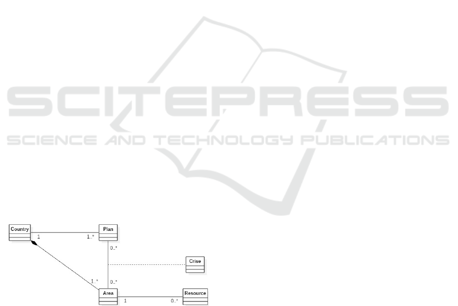
ries, material damage, etc. Figure 2 represents a class
diagram that describes the structure of a crisis mana-
gement system by showing the relationships among
its constituents.
Figure 2: Class diagram of crisis management system.
An operating mode represents an activated plan. It
defines its geographical scope, manages its resour-
ces and organizes the communication with all partici-
pants. However, if a series of crises occurs in the same
area, the decision-maker can then change the activa-
ted plan by another one covering more areas. Also, if
a new crisis triggers a plan in an area affected by anot-
her crisis plan, then these two crises will be treated by
one new plan. This new plan is the merger of the first
two and takes into consideration all areas concerned
by the first two crises. This dynamic is ensured by the
operating mode management, which allows CMS to
switch from one operating mode to another one wit-
hout having to stop.
Furthermore, the multi-model approach is used
to allow, in context of SCT, to associate a PCPN
model with each operating mode. First, let Pl =
{pl
1
, pl
2
,..., pl
|Pl|
}, where |Pl| ≥ 1 be the set of plans
and let A = {a
1
,a
2
,..., a
|A|
}, where |A| ≥ 1 be its set of
the areas. Also, let A
i, j
,∀i ∈ {1..|A|},∀ j ∈ {1..|Pl|}
be the set of the areas concerned by the crisis in a
i
and
the plan pl
j
.
Let PL the set of all CMS operating modes where
A × Pl −→ PL
(a
i
, pl
j
) 7−→ PL
i, j
be a mapping such that PL
i, j
indicates the operating
mode associated to the crisis area a
i
and to the plan
pl
j
.
For each operating mode PL
i, j
, where
i ∈ 1..|A| and j ∈ 1..|Pl|, we associate a PCPN
< P
i, j
,T
i, j
,C
i, j
,Pre
i, j
,Post
i, j
,G
i, j
,M
i, j
,Π
i, j
>.
For reasons of simplicity, the same identity of each
PL mode is given to its associated PCPN.
3.1 Common Operating Mode in CMS
Each plan can be applied in one or more areas throug-
hout a country. These areas are subject to the same
degree of action. Therefore, the same functioning
process appears for crises activating the same plan,
which leads us to define the common operating mode
concept.
Formally, two operating modes of two different
crisis areas are common if and only if they are mo-
deled by the same PCPN model except tokens.
Definition 2. Let PL
i, j
= (P
i, j
,T
i, j
,C
i, j
,Pre
i, j
,Post
i, j
,
G
i, j
,M
i, j
,Π
i, j
) and PL
k, j
= (P
k, j
,T
k, j
,C
k, j
,Pre
k, j
,
Post
k, j
,G
k, j
,M
k, j
,Π
k, j
) be two operating modes such
as i 6= k. PL
i, j
and PL
k, j
are common, if and only if
(P
i, j
,T
i, j
,C
i, j
,Pre
i, j
,Post
i, j
,G
i, j
,Π
i, j
) = (P
k, j
,T
k, j
,
C
k, j
,Pre
k, j
,Post
k, j
,G
k, j
,Π
k, j
).
3.2 Common Sub-behavior in CMS
For each plan level, the associated public safety
agencies such as police, fire brigades, and emer-
gency medical services are made available to the
decision-maker. Thus, some similar behaviors bet-
ween operating modes of different level plans can be
underlined and in order to minimize the global model
size, a concept common Sub-behavior is defined.
A Formal Approach for Multi-occurrence Crisis Management
609

Formally, a common Sub-behavior is a part of a
PCPN related to one or more operating modes. It can
be a set of places, a set of transitions and/or a set of
tokens.
Definition 3. Let PL be the set of operating modes.
∀(PL
i, j
,PL
k,l
) ∈ PL × PL such as i 6= k and j 6= l,
if ∃c =< P
c
,T
c
,C
c
,Pre
c
,Post
c
,G
c
,M
c
,Π
c
> such
as (P
c
= (P
i, j
∩ P
k,l
) 6=
/
0) or (T
c
= (T
i, j
∩ T
k,l
) 6=
/
0) or (M
c
= (M
i, j
∩ M
k,l
) 6=
/
0) then c is a common
Sub-behavior for the two modes PL
i, j
and PL
k,l
.
Remark 1. Common operating mode and common
Sub-behavior are defined when the same name of
PCPN components is given in different model.
3.3 Switching Mechanism
A switching event triggers between two operating mo-
des under decision-maker request or between three in
the case of merging activated plans. It causes the de-
activation of the current operating mode and the acti-
vation of another mode.
The switching mechanism is modeled by speci-
fic PCPN transitions in a given mode. To distinguish
such transitions, a mapping is defined which role is to
provide the information for the next mode.
Definition 4. Let PL
i, j
be an operating mode and
T
0
i, j
⊂ T
i, j
be the set of switching transitions.
Let Next_plan : T
0
i, j
→ PL be a mapping such that
Next_plan(t) indicates the active operating mode af-
ter firing t (∀t ∈ T
0
i, j
).
Merging Operating Modes. As stated above, mer-
ging operating modes is triggered automatically when
a new plan is activated in an area concerned by anot-
her crisis via fusion transitions. These transitions are
switching transitions with a higher priority than ot-
hers.
Formally,
Definition 5. Let PL
i, j
, i ∈ {1..|A|}, j ∈ {1..|Pl|} and
PL
k,l
, k ∈ {1..|A|}, l ∈ {1..|Pl|} two operating modes.
If a
k
∈ A
i, j
, then PL
i, j
and PL
k,l
are replaced by a new
operating modes PL
m,n
such as PL
m,n
is the concate-
nation of PL
i, j
and PL
k,l
and A
m,n
= A
i, j
∪ A
k,l
.
3.4 System Model
On the basis of the previous concept definitions, we
are able now to model the CMS based on the ope-
rating modes management. Let the place containing
all the areas concerned by the different crises called
ActivatedPlans with tokens that have the structure
((a
i
, pl
j
),A
i, j
).
The associate PCPN is a tuple
< P,T,C, Pre,Post,G, M,Π >
Where
P = ∪
(i=1..|A|, j=1..|Pl|)
P
i, j
;
T = ∪
(i=1..|A|, j=1..|Pl|)
T
i, j
;
C = ∪
(i=1..|A|, j=1..|Pl|)
C
i, j
;
Pre,Post :
• ∀PL
i, j
∈ PL,∀(p,t) ∈ P
i, j
× T
i, j
,
Pre(p,t) = Pre
i, j
(p,t),
Post(p,t) = Post
i, j
(p,t);
• ∀(PL
i, j
,PL
k,l
) ∈ PL×PL(i 6= k),∀(p,t) ∈ P
i, j
×
T
k,l
/p /∈ P
k,l
and t /∈ T
i, j
,
Pre(p,t) = Post(p,t) = 0;
• ∀PL
i, j
∈ PL,∀t ∈ T
0
k,l
,
Post(ActivatedPlans,t) = Next_plan(t);
where T
0
i, j
is the set of switching transitions
such as T
0
i, j
⊂ T
i, j
.
G : ∀PL
i, j
∈ PL,∀t ∈ T
i, j
, G(t) = G
i, j
(t);
M : ∀(PL
i, j
,PL
k,l
) ∈ PL × PL(i 6= k)
• if j = l, M(p) = M
i, j
(p) ∪ M
k,l
(p);
• if j 6= l, if M
i, j
(p) ∈ M
c
(p),
M(p) = M
c
(p); else
M(p) = M
i, j
(p).
Π : ∀PL
i, j
∈ PL,∀t ∈ T
i, j
, Π(p) = Π
i, j
(p).
3.5 Generation Algorithm
Let us present the algorithm generating the CMS
model from a set CM operating modes.
Definition 1. Generating the CMS model
Input
- the set A of Areas
- the set Pl of plans
- the set PL of operating modes
- the mapping Next_plan
Output
a global CP-net
G =< P,T,C,Pre,Post, G,M,Π >
Initially
P = ∅; T = ∅; C = ∅;
For every operating mode (i, j) i = 1..|A|, j =
1..|Pl| do /*include a new mode*/
ICSOFT 2018 - 13th International Conference on Software Technologies
610
P = P ∪ P
i, j
; T = T ∪ T
i, j
; C = C ∪C
i, j
;
∀(p,t) ∈ P
i, j
×T
i, j
, /*defining internal PL
i, j
arcs
*/
Pre(p,t) = Pre
i, j
(p,t);
Post(p,t) = Post
i, j
(p,t);
∀t ∈ T
0
i, j
, /*defining the new arcs*/
Post(ActivatedPlans,t) = Next_plan(t);
∀t ∈ T
i, j
, /*adding guards*/
G(t) = G
i, j
(t);
∀p ∈ P
i, j
, /*defining initial marking*/
M(p) = M(p) ∪ M
i, j
(p);
∀t ∈ T
i, j
, /*defining priorities*/
Π(t) = Π
i, j
(t);
For every mode (k,l), k = 1. . . (i−1),l = 1. . . ( j −
1) do /*already included modes defining inexistent
arcs*/
∀(p,t) ∈ P
i, j
× T
k,l
, p /∈ P
k,l
and t /∈ T
i, j
,
Pre(p,t) = Post
i, j
(p,t) = 0;
enddo
enddo.
4 CASE STUDY
The example below is developed using the environ-
ment CPN Tools (Ratzer et al., 2003). It is a free soft-
ware for editing, simulating, and analyzing Colored
Petri nets.
4.1 System Description
To start with we suppose that in the country of the
studied example, there are 3 levels of plans:
• Plan1 is for limited crises which will not seriously
affect the functional capacity of the concerned
area and will not exceed the available resources
in that area but nevertheless require some degree
of action;
• Plan2 is for emergency or disaster which may
be severe and cause damage, fatalities or injuries
and/or interruption to the concerned area operati-
ons and it may develop from incidents beginning
at the Plan1. The resources of the area concerned
and those of the neighboring areas are made avai-
lable to the decision-maker;
• Plan3 is for major crisis such as natural disasters
and can be caused by incidents beginning at the
Plan2. In this plan, the resources of the concerned
area, of all its neighbors and of the neighbors of
the neighbors are made available to the decision-
maker.
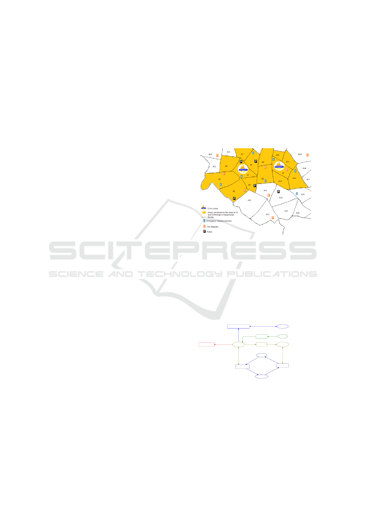
The example represents a series of coordinated explo-
sions in two passenger trains. Such blasts kill people
and leave many others critically injured. We suppose
that the blasts of the train in area A1 happened a few
minutes before the second one. Plan2 is triggered in
A1 then the same plan is also triggered in A7 with the
incident of the second train. In such a situation of
plans overlapping and in order to respond effectively,
a new plan is created by merging the two previous
modes: the decision-maker of the first incident beco-
mes also the one for the second. Their plans’ areas
are merged. Figure 3 shows a situation map of the
example where the yellow color represents the areas
concerned by the new plan.
Figure 3: Situation map.
4.2 PCPN Models
To better understand the global model, we begin by
describing each common operation mode that corre-
sponds to each plan level in distinct PCPN models.
This generic study allows to understand any opera-
ting mode triggered in any plan level.
In the studied example, there are 4 common operating
mode: {Plan1,Plan2,Plan3,MergedPlans}.
Idle Resources
ResourceXArea
1`(Police,A1)++
1`(Police,A3)++
1`(Police,A4)++
1`(Police,A6)++
1`(Police,A15)++
1`(Hospital,A1)++
1`(Hospital,A2)++
1`(Hospital,A5)++
1`(Hospital,A6)++
1`(Hospital,A7)++
1`(Hospital,A12)++
1`(Hospital,A16)++
1`(Hospital,A25)++
1`(Firefighter,A2)++
1`(Firefighter,A3)++
1`(Firefighter,A5)++
1`(Firefighter,A7)++
1`(Firefighter,A14)++
1`(Firefighter,A19)++
1`(Firefighter,A20)++
1`(Firefighter,A24)
Active Resources
ResourceXArea
Activated Plans
ListCriseXAreaXPlanXConcernedAreas
Areas
Plan1
Area
1`A1++
1`A2++
1`A3++
1`A4++
1`A5++
1`A6++
1`A7++
1`A8++
1`A9++
1`A10++
1`A11++
1`A12++
1`A13++
1`A14++
1`A15++
1`A16++
1`A17++
1`A18++
1`A19++
1`A20++
1`A21++
1`A22++
1`A23++
1`A24++
1`A25++
1`A26
Areas Plan 2
Neighbors
1`(A1,[A2,A3,A4,A5,A6,A7,A8])++
1`(A2,[A1,A3,A4,A8,A21])++
1`(A3,[A1,A2,A4,A23])++
1`(A4,[A1,A3,A5,A14,A23])++
1`(A5,[A1,A4,A6,A9,A13,A14])++
1`(A6,[A1,A5,A7,A9])++
1`(A7,[A5,A9,A10,A11,A12,A13])++
1`(A8,[A1,A2,A20,A21,A22])++
1`(A9,[A5,A6,A7,A10])++
1`(A10,[A7,A9,A11,A19])++
1`(A11,[A7,A10,A12,A18,A19])++
1`(A12,[A7,A11,A13,A15,A16,A18])++
1`(A13,[A5,A7,A12,A14,A15,A16])++
1`(A14,[A4,A5,A13,A15,A23,A24])++
1`(A15,[A13,A14,A16,A24,A25])++
1`(A16,[A12,A13,A15,A25,A26])++
1`(A17,[A12,A16,A18])++
1`(A18,[A11,A12,A17,A19])++
1`(A19,[A11,A18])++
1`(A20,[A8,A21,A22])++
1`(A21,[A2,A8,A20,A22])++
1`(A22,[A7,A8,A20])++
1`(A23,[A3,A4,A14,A24])++
1`(A24,[A14,A15,A23,A25])++
1`(A25,[A15,A16,A24,A26])++
1`(A26,[A16,A25])
Enabled Plans
ListCriseXAreaXPlanXConcernedAreas
Activate Resource
[mem ln a ]
Disable Resource
[mem ln a]
P_HIGH
Disable Plan
Activate Plan1
Change Plan 1 to Plan 2 test
[ mem lcap (c,a,Plan1)]
Merging Crises Areas
[(intersect ln1 ln2)<>[]]
P_HIGH
(r,a)
(r,a)
1`(lcap,ln)
(r,a)
(r,a)
a
([(c,a,Plan1)],[a])
1`(lcap,ln)
1`(lcap,ln)
1`(lcap,ln)
1`(lcap,ln)
(a,ln1)
1`(lcap1,ln1)++1`(lcap2,ln2)
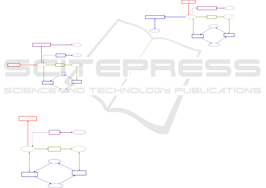
Figure 4: Plan1 model.
Figure 4 represents the CMS behavior in the Plan1 as
well as the management of allocate resources , it may
be stated:
• The triggering / shutting down of Plan1 is repre-
sented by the state machine made up of places
A Formal Approach for Multi-occurrence Crisis Management
611
{ActivatedPlans,EnabledPlans,AreasPlan1},
transitions {ActivatePlan1,DisablePlan} and the
arcs that interconnect them.
• Each token of {ActivatedPlans,EnabledPlans}
is a couple of lists. The first list contains a couple
of values: the crisis area and the activated plan.
The second list contains areas concerned by the
activated plan.
• The behavior of the use/release of permit-
ted resources is represented by the places
{IdleResources, ActiveResources} and their rela-
ted arcs.
• Transitions ChangePlan1toPlan2 and
MergingCrisesAreas are switching transitions
(i.e. Next_plan(Change Plan1toPlan2) = Plan2
and
Next_plan(MergingCrisesAreas) =
MergedPlans). Moreover, the transition
MergingCrisesAreas is a high-priority tran-
sition and it implies the merging plans in the
situation of overlapping areas.
Idle Resources
ResourceXArea
1`(Police,A1)++
1`(Police,A3)++
1`(Police,A4)++
1`(Police,A6)++
1`(Police,A15)++
1`(Hospital,A1)++
1`(Hospital,A2)++
1`(Hospital,A6)++
1`(Hospital,A7)++
1`(Hospital,A15)++
1`(Hospital,A16)++
1`(Firefighter,A2)++
1`(Firefighter,A3)++
1`(Firefighter,A5)++
1`(Firefighter,A7)
Active Resources
ResourceXArea
Activated Plans
ListCriseXAreaXPlanXConcernedAreas
Areas Plan 2
Neighbors
1`(A1,[A2,A3,A4,A5,A6,A7,A8])++
1`(A2,[A1,A3,A4,A8,A21])++
1`(A3,[A1,A2,A4,A23])++
1`(A4,[A1,A3,A5,A14,A23])++
1`(A5,[A1,A4,A6,A9,A13,A14])++
1`(A6,[A1,A5,A7,A9])++
1`(A7,[A5,A9,A10,A11,A12,A13])++
1`(A8,[A1,A2,A20,A21,A22])++
1`(A9,[A5,A6,A7,A10])++
1`(A10,[A7,A9,A11,A19])++
1`(A11,[A7,A10,A12,A18,A19])++
1`(A12,[A7,A11,A13,A15,A16,A18])++
1`(A13,[A5,A7,A12,A14,A15,A16])++
1`(A14,[A4,A5,A13,A15,A23,A24])++
1`(A15,[A13,A14,A16,A24,A25])++
1`(A16,[A12,A13,A15,A25,A26])++
1`(A17,[A12,A16,A18])++
1`(A18,[A11,A12,A17,A19])++
1`(A19,[A11,A18])++
1`(A20,[A8,A21,A22])++
1`(A21,[A2,A8,A20,A22])++
1`(A22,[A7,A8,A20])++
1`(A23,[A3,A4,A14,A24])++
1`(A24,[A14,A15,A23,A25])++
1`(A25,[A15,A16,A24,A26])++
1`(A26,[A16,A25])
Enabled Plans
ListCriseXAreaXPlanXConcernedAreas
Areas Plan3
Neighbors
1`(A1,[A1,A10,A11,A12,A13,A14,A20,A21,A22,A23,A9,A2,A3,A4,A5,A6,A7,A8])++
1`(A2,[A2,A20,A22,A6,A7,A5,A14,A23,A1,A3,A4,A8,A21])++
1`(A3,[A3,A24,A6,A7,A8,A21,A5,A14,A1,A2,A4,A23])++
1`(A4,[A4,A9,A2,A6,A7,A8,A13,A15,A24,A1,A3,A5,A14,A23])++
1`(A5,[A5,A2,A8,A3,A10,A12,A16,A15,A23,A24,A7,A1,A4,A6,A9,A13,A14])++
1`(A6,[A6,A14,A10,A11,A12,A13,A2,A3,A4,A8,A1,A5,A7,A9])++
1`(A7,[A7,A1,A4,A6,A14,A19,A15,A16,A18,A5,A9,A10,A11,A12,A13])++
1`(A8,[A8,A5,A6,A7,A3,A4,A1,A2,A20,A21,A22])++
1`(A9,[A9,A4,A14,A12,A13,A1,A11,A19,A5,A6,A7,A10])++
1`(A10,[A10,A13,A12,A5,A6,A18,A7,A9,A11,A19])++
1`(A11,[A11,A15,A16,A5,A9,A13,A17,A7,A10,A12,A18,A19])++
1`(A12,[A12,A24,A14,A25,A26,A17,A19,A5,A9,A10,A7,A11,A13,A15,A16,A18])++
1`(A13,[A13,A23,A1,A4,A6,A24,A25,A26,A9,A10,A11,A18,A5,A7,A12,A14,A15,A16])++
1`(A14,[A7,A12,A16,A25,A6,A9,A1,A3,A14,A4,A5,A13,A15,A23,A24])++
1`(A15,[A26,A4,A5,A7,A12,A15,A23,A13,A14,A16,A24,A25])++
1`(A16,[A5,A7,A11,A18,A14,A16,A24,A12,A13,A15,A25,A26])++
1`(A17,[A17,A19,A25,A26,A7,A11,A13,A15,A12,A16,A18])++
1`(A18,[A10,A7,A13,A15,A16,A18,A11,A12,A17,A19])++
1`(A19,[A7,A10,A12,A17,A19,A11,A18])++
1`(A20,[A7,A1,A2,A20,A8,A21,A22])++
1`(A21,[A7,A1,A3,A4,A21,A2,A8,A20,A22])++
1`(A22,[A5,A9,A10,A11,A12,A13,A1,A2,A21,A22,A7,A8,A20])++
1`(A23,[A13,A5,A15,A25,A1,A2,A23,A3,A4,A14,A24])++
1`(A24,[A5,A13,A3,A4,A16,A24,A26,A14,A15,A23,A25])++
1`(A25,[A12,A13,A14,A23,A25,A15,A16,A24,A26])++
1`(A26,[A12,A13,A15,A24,A26,A16,A25])
Activate Resource
[mem ln a ]
Disable Resource
[mem ln a]
P_HIGH
Disable Plan
Activate Plan2
Merging Crises Areas
[(intersect ln1 ln2)<>[]]
P_HIGH
Change Plan 2 to Plan 3
[ mem lcap (c,a,Plan2)]
(r,a)
(r,a)
1`(lcap,ln)
(r,a)
(r,a)
([(c,a,Plan2)],a::ln) (a,ln)
1`(lcap1,ln1)++1`(lcap2,ln2)
1`(lcap,ln)
1`(lcap,ln)
1`(lcap,ln)
1`(lcap,ln)
(a,ln1)
Figure 5: Plan2 model.
Idle Resources
ResourceXArea
1`(Police,A1)++
1`(Police,A3)++
1`(Police,A4)++
1`(Police,A6)++
1`(Police,A15)++
1`(Hospital,A1)++
1`(Hospital,A2)++
1`(Hospital,A6)++
1`(Hospital,A7)++
1`(Hospital,A15)++
1`(Hospital,A16)++
1`(Firefighter,A2)++
1`(Firefighter,A3)++
1`(Firefighter,A5)++
1`(Firefighter,A7)
Active Resources
ResourceXArea
Activated Plans
ListCriseXAreaXPlanXConcernedAreas
Enabled Plans
ListCriseXAreaXPlanXConcernedAreas
Areas Plan3
Neighbors
1`(A1,[A1,A10,A11,A12,A13,A14,A20,A21,A22,
A23,A9,A2,A3,A4,A5,A6,A7,A8])++
1`(A2,[A2,A20,A22,A6,A7,A5,A14,A23,A1,A3,
A4,A8,A21])++
1`(A3,[A3,A24,A6,A7,A8,A21,A5,A14,A1,A2,
A4,A23])++
1`(A4,[A4,A9,A2,A6,A7,A8,A13,A15,A24,A1,A3
,A5,A14,A23])++
1`(A5,[A5,A2,A8,A3,A10,A12,A16,A15,A23,A24
,A7,A1,A4,A6,A9,A13,A14])++
1`(A6,[A6,A14,A10,A11,A12,A13,A2,A3,A4,A8,
A1,A5,A7,A9])++
1`(A7,[A7,A1,A4,A6,A14,A19,A15,A16,A18,A5,
A9,A10,A11,A12,A13])++
1`(A8,[A8,A5,A6,A7,A3,A4,A1,A2,A20,A21,A22])++
1`(A9,[A9,A4,A14,A12,A13,A1,A11,A19,A5,A6,
A7,A10])++
1`(A10,[A10,A13,A12,A5,A6,A18,A7,A9,A11,
A19])++
1`(A11,[A11,A15,A16,A5,A9,A13,A17,A7,A10,
A12,A18,A19])++
1`(A12,[A12,A24,A14,A25,A26,A17,A19,A5,A9,
A10,A7,A11,A13,A15,A16,A18])++
1`(A13,[A13,A23,A1,A4,A6,A24,A25,A26,A9,A10,
A11,A18,A5,A7,A12,A14,A15,A16])++
1`(A14,[A7,A12,A16,A25,A6,A9,A1,A3,A14,A4,
A5,A13,A15,A23,A24])++
1`(A15,[A26,A4,A5,A7,A12,A15,A23,A13,A14,
A16,A24,A25])++
1`(A16,[A5,A7,A11,A18,A14,A16,A24,A12,A13,
A15,A25,A26])++
1`(A17,[A17,A19,A25,A26,A7,A11,A13,A15,
A12,A16,A18])++
1`(A18,[A10,A7,A13,A15,A16,A18,A11,A12,
A17,A19])++
1`(A19,[A7,A10,A12,A17,A19,A11,A18])++
1`(A20,[A7,A1,A2,A20,A8,A21,A22])++
1`(A21,[A7,A1,A3,A4,A21,A2,A8,A20,A22])++
1`(A22,[A5,A9,A10,A11,A12,A13,A1,A2,A21,
A22,A7,A8,A20])++
1`(A23,[A13,A5,A15,A25,A1,A2,A23,A3,A4,
A14,A24])++
1`(A24,[A5,A13,A3,A4,A16,A24,A26,A14,A15,
A23,A25])++
1`(A25,[A12,A13,A14,A23,A25,A15,A16,A24,
A26])++
1`(A26,[A12,A13,A15,A24,A26,A16,A25])
Activate Resource
[mem ln a ]
Disable Resource
[mem ln a]
P_HIGH
Disable Plan
Merging Crises Areas
[(intersect ln1 ln2)<>[]]
P_HIGH
Activate Plan3
(r,a)
(r,a)
1`(lcap,ln)
(r,a)
(r,a)
1`(lcap1,ln1)++1`(lcap2,ln2)
1`(lcap,ln)
1`(lcap,ln)
1`(lcap,ln)
1`(a,ln)([(c,a,Plan3)],a::ln)
Figure 6: Plan3 model.
Figure 5 (resp. Figure 6) describes the behavior of the
functioning in the Plan2 (resp. Plan3 ). We can note
the following points:
• The activation of a crisis in the Plan2 (resp.
Plan3) is represented by the transition
ActivatePlan2 (resp. ActivatePlan3). The
place AreasPlan2 (resp.
AreasPlan3) represents the area of crisis, its
neighbors areas concerned by the crisis when
Plan2 (resp.Plan3) is applied.
• A common sub-behavior between the
models appears through the places
{IdleResources, ActiveResources, Activated
Plans,EnabledPlans} and transitions
{Activate Resource, DisableResource,
DisablePlan, MergingCrisesAreas}. In fact,
they keep the same name. Their internal arcs are
the same also.
• Transition ChangePlan2toPlan3 is a swit-
ching transition that allows the system to
change Plan2 to Plan3 of a current crisis (i.e.
Next_plan(Change− Plan2toPlan3) = Plan3 ).
Idle Resources
ResourceXArea
1`(Police,A1)++
1`(Police,A3)++
1`(Police,A4)++
1`(Police,A6)++
1`(Police,A15)++
1`(Hospital,A1)++
1`(Hospital,A2)++
1`(Hospital,A5)++
1`(Hospital,A6)++
1`(Hospital,A7)++
1`(Hospital,A12)++
1`(Hospital,A16)++
1`(Hospital,A25)++
1`(Firefighter,A2)++
1`(Firefighter,A3)++
1`(Firefighter,A5)++
1`(Firefighter,A7)++
1`(Firefighter,A14)++
1`(Firefighter,A19)++
1`(Firefighter,A20)++
1`(Firefighter,A24)
Active Resources
ResourceXArea
Activated Plans
ListCriseXAreaXPlanXConcernedAreas
Areas Plan 2
Neighbors
1`(A1,[A2,A3,A4,A5,A6,A7,A8])++
1`(A2,[A1,A3,A4,A8,A21])++
1`(A3,[A1,A2,A4,A23])++
1`(A4,[A1,A3,A5,A14,A23])++
1`(A5,[A1,A4,A6,A9,A13,A14])++
1`(A6,[A1,A5,A7,A9])++
1`(A7,[A5,A9,A10,A11,A12,A13])++
1`(A8,[A1,A2,A20,A21,A22])++
1`(A9,[A5,A6,A7,A10])++
1`(A10,[A7,A9,A11,A19])++
1`(A11,[A7,A10,A12,A18,A19])++
1`(A12,[A7,A11,A13,A15,A16,A18])++
1`(A13,[A5,A7,A12,A14,A15,A16])++
1`(A14,[A4,A5,A13,A15,A23,A24])++
1`(A15,[A13,A14,A16,A24,A25])++
1`(A16,[A12,A13,A15,A25,A26])++
1`(A17,[A12,A16,A18])++
1`(A18,[A11,A12,A17,A19])++
1`(A19,[A11,A18])++
1`(A20,[A8,A21,A22])++
1`(A21,[A2,A8,A20,A22])++
1`(A22,[A7,A8,A20])++
1`(A23,[A3,A4,A14,A24])++
1`(A24,[A14,A15,A23,A25])++
1`(A25,[A15,A16,A24,A26])++
1`(A26,[A16,A25])
Enabled Plans
ListCriseXAreaXPlanXConcernedAreas
Areas Plan3
Neighbors
1`(A1,[A1,A10,A11,A12,A13,A14,A20,A21,A22,
A23,A9,A2,A3,A4,A5,A6,A7,A8])++
1`(A2,[A2,A20,A22,A6,A7,A5,A14,A23,A1,A3,
A4,A8,A21])++
1`(A3,[A3,A24,A6,A7,A8,A21,A5,A14,A1,A2,
A4,A23])++
1`(A4,[A4,A9,A2,A6,A7,A8,A13,A15,A24,A1,A3
,A5,A14,A23])++
1`(A5,[A5,A2,A8,A3,A10,A12,A16,A15,A23,A24
,A7,A1,A4,A6,A9,A13,A14])++
1`(A6,[A6,A14,A10,A11,A12,A13,A2,A3,A4,A8,
A1,A5,A7,A9])++
1`(A7,[A7,A1,A4,A6,A14,A19,A15,A16,A18,A5,
A9,A10,A11,A12,A13])++
1`(A8,[A8,A5,A6,A7,A3,A4,A1,A2,A20,A21,A22])++
1`(A9,[A9,A4,A14,A12,A13,A1,A11,A19,A5,A6,
A7,A10])++
1`(A10,[A10,A13,A12,A5,A6,A18,A7,A9,A11,
A19])++
1`(A11,[A11,A15,A16,A5,A9,A13,A17,A7,A10,
A12,A18,A19])++
1`(A12,[A12,A24,A14,A25,A26,A17,A19,A5,A9,
A10,A7,A11,A13,A15,A16,A18])++
1`(A13,[A13,A23,A1,A4,A6,A24,A25,A26,A9,A10,
A11,A18,A5,A7,A12,A14,A15,A16])++
1`(A14,[A7,A12,A16,A25,A6,A9,A1,A3,A14,A4,
A5,A13,A15,A23,A24])++
1`(A15,[A26,A4,A5,A7,A12,A15,A23,A13,A14,
A16,A24,A25])++
1`(A16,[A5,A7,A11,A18,A14,A16,A24,A12,A13,
A15,A25,A26])++
1`(A17,[A17,A19,A25,A26,A7,A11,A13,A15,
A12,A16,A18])++
1`(A18,[A10,A7,A13,A15,A16,A18,A11,A12,
A17,A19])++
1`(A19,[A7,A10,A12,A17,A19,A11,A18])++
1`(A20,[A7,A1,A2,A20,A8,A21,A22])++
1`(A21,[A7,A1,A3,A4,A21,A2,A8,A20,A22])++
1`(A22,[A5,A9,A10,A11,A12,A13,A1,A2,A21,
A22,A7,A8,A20])++
1`(A23,[A13,A5,A15,A25,A1,A2,A23,A3,A4,
A14,A24])++
1`(A24,[A5,A13,A3,A4,A16,A24,A26,A14,A15,
A23,A25])++
1`(A25,[A12,A13,A14,A23,A25,A15,A16,A24,
A26])++
1`(A26,[A12,A13,A15,A24,A26,A16,A25])
Activate Resource
[mem ln a ]
Disable Resource
[mem ln a]
P_HIGH
Disable Plan
Merging Crises Areas
[(intersect ln1 ln2)<>[]]
P_HIGH
Change Plan 1 to Plan 2 test
[ mem lcap (c,a,Plan1)]
Change Plan 2 to Plan 3
[ mem lcap (c,a,Plan2)]
(r,a)
(r,a)
1`(lcap,ln)
(r,a)
(r,a)
1`(lcap1^^lcap2,remdupl (ln1^^ln2))
1`(lcap,ln)
1`(lcap,ln)
1`(lcap,ln)
1`(lcap,ln)
(a,ln1)
1`(lcap,ln)
(a,ln1)
Figure 7: Models of merged plans.
The functioning of the mode Merged plans, mo-
deled in Figure 7, is similar to the other plans with the
ability to switch the plans for each crisis that compose
the merged crisis to another coverage plan of larger
areas.
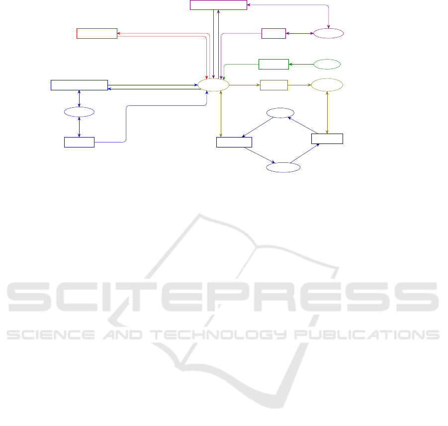
Figure 8 presents the global PCPN describing the
operating modes management for the crisis manage-
ment. In this model, all places, transitions, arcs and
tokens of the four common operating modes are pre-
sented without duplicating the common sub-behavior.
Moreover, new arcs are added in order to express the
mode management:
• The place AreasPlan2 (resp. AreasPlan3) is
connected to the transition ChangePlan1toPlan2
(resp. ChangePlan2toPlan3) by a bidirectional
arc labeled by (a,ln1).
• The transition ChangePlan1toPlan2 (resp.
ChangePlan2toPlan3) is connected
to the place ActivatedPlans by
an arc labeled by 1‘((a,Plan2) ::
(rm(a, Plan1)lcap), remdupl(ln1dln))(resp.
1‘((a,Plan3)::(rm (a,Plan2) lcap),
remdupl (ln1dln))) allowing the replacement of
the plan by a new one and updating the list of the
concerned areas crisis.
• The transition MergingCrisesAreas is connected
ICSOFT 2018 - 13th International Conference on Software Technologies
612
Idle Resources
ResourceXArea
1`(Police,A1)++
1`(Police,A3)++
1`(Police,A4)++
1`(Police,A6)++
1`(Police,A15)++
1`(Hospital,A1)++
1`(Hospital,A2)++
1`(Hospital,A6)++
1`(Hospital,A7)++
1`(Hospital,A15)++
1`(Hospital,A16)++
1`(Firefighter,A2)++
1`(Firefighter,A3)++
1`(Firefighter,A5)++
1`(Firefighter,A7)
Active Resources
ResourceXArea
Activated Plans
ListCriseXAreaXPlanXConcernedAreas
Areas
Plan1
Area
1`A1++
1`A2++
1`A3++
1`A4++
1`A5++
1`A6++
1`A7++
1`A8++
1`A9++
1`A10++
1`A11++
1`A12++
1`A13++
1`A14++
1`A15++
1`A16++
1`A17++
1`A18++
1`A19++
1`A20++
1`A21++
1`A22++
1`A23++
1`A24++
1`A25++
1`A26
Areas Plan 2
Neighbors
1`(A1,[A2,A3,A4,A5,A6,A7,A8])++
1`(A2,[A1,A3,A4,A8,A21])++
1`(A3,[A1,A2,A4,A23])++
1`(A4,[A1,A3,A5,A14,A23])++
1`(A5,[A1,A4,A6,A9,A13,A14])++
1`(A6,[A1,A5,A7,A9])++
1`(A7,[A5,A9,A10,A11,A12,A13])++
1`(A8,[A1,A2,A20,A21,A22])++
1`(A9,[A5,A6,A7,A10])++
1`(A10,[A7,A9,A11,A19])++
1`(A11,[A7,A10,A12,A18,A19])++
1`(A12,[A7,A11,A13,A15,A16,A18])++
1`(A13,[A5,A7,A12,A14,A15,A16])++
1`(A14,[A4,A5,A13,A15,A23,A24])++
1`(A15,[A13,A14,A16,A24,A25])++
1`(A16,[A12,A13,A15,A25,A26])++
1`(A17,[A12,A16,A18])++
1`(A18,[A11,A12,A17,A19])++
1`(A19,[A11,A18])++
1`(A20,[A8,A21,A22])++
1`(A21,[A2,A8,A20,A22])++
1`(A22,[A7,A8,A20])++
1`(A23,[A3,A4,A14,A24])++
1`(A24,[A14,A15,A23,A25])++
1`(A25,[A15,A16,A24,A26])++
1`(A26,[A16,A25])
Enabled Plans
ListCriseXAreaXPlanXConcernedAreas
Areas Plan3
Neighbors
1`(A1,[A1,A10,A11,A12,A13,A14,A20,A21,A22,
A23,A9,A2,A3,A4,A5,A6,A7,A8])++
1`(A2,[A2,A20,A22,A6,A7,A5,A14,A23,A1,A3,
A4,A8,A21])++
1`(A3,[A3,A24,A6,A7,A8,A21,A5,A14,A1,A2,
A4,A23])++
1`(A4,[A4,A9,A2,A6,A7,A8,A13,A15,A24,A1,A3
,A5,A14,A23])++
1`(A5,[A5,A2,A8,A3,A10,A12,A16,A15,A23,A24
,A7,A1,A4,A6,A9,A13,A14])++
1`(A6,[A6,A14,A10,A11,A12,A13,A2,A3,A4,A8,
A1,A5,A7,A9])++
1`(A7,[A7,A1,A4,A6,A14,A19,A15,A16,A18,A5,
A9,A10,A11,A12,A13])++
1`(A8,[A8,A5,A6,A7,A3,A4,A1,A2,A20,A21,A22])++
1`(A9,[A9,A4,A14,A12,A13,A1,A11,A19,A5,A6,
A7,A10])++
1`(A10,[A10,A13,A12,A5,A6,A18,A7,A9,A11,
A19])++
1`(A11,[A11,A15,A16,A5,A9,A13,A17,A7,A10,
A12,A18,A19])++
1`(A12,[A12,A24,A14,A25,A26,A17,A19,A5,A9,
A10,A7,A11,A13,A15,A16,A18])++
1`(A13,[A13,A23,A1,A4,A6,A24,A25,A26,A9,A10,
A11,A18,A5,A7,A12,A14,A15,A16])++
1`(A14,[A7,A12,A16,A25,A6,A9,A1,A3,A14,A4,
A5,A13,A15,A23,A24])++
1`(A15,[A26,A4,A5,A7,A12,A15,A23,A13,A14,
A16,A24,A25])++
1`(A16,[A5,A7,A11,A18,A14,A16,A24,A12,A13,
A15,A25,A26])++
1`(A17,[A17,A19,A25,A26,A7,A11,A13,A15,
A12,A16,A18])++
1`(A18,[A10,A7,A13,A15,A16,A18,A11,A12,
A17,A19])++
1`(A19,[A7,A10,A12,A17,A19,A11,A18])++
1`(A20,[A7,A1,A2,A20,A8,A21,A22])++
1`(A21,[A7,A1,A3,A4,A21,A2,A8,A20,A22])++
1`(A22,[A5,A9,A10,A11,A12,A13,A1,A2,A21,
A22,A7,A8,A20])++
1`(A23,[A13,A5,A15,A25,A1,A2,A23,A3,A4,
A14,A24])++
1`(A24,[A5,A13,A3,A4,A16,A24,A26,A14,A15,
A23,A25])++
1`(A25,[A12,A13,A14,A23,A25,A15,A16,A24,
A26])++
1`(A26,[A12,A13,A15,A24,A26,A16,A25])
Activate Resource
[mem ln a ]
Disable Resource
[mem ln a]
P_HIGH
Disable Plan
Activate Plan1
Activate Plan2
Merging Crises Areas
[(intersect ln1 ln2)<>[]]
P_HIGH
Change Plan 1 to Plan 2 test
[ mem lcap (c,a,Plan1)]
Activate Plan3
Change Plan 2 to Plan 3
[ mem lcap (c,a,Plan2)]
(r,a)
(r,a)
1`(lcap,ln)
(r,a)
(r,a)
a
([(c,a,Plan1)],[a])
([(c,a,Plan2)],a::ln)
(a,ln)
1`(lcap1,ln1)++1`(lcap2,ln2)
1`(lcap1^^lcap2,remdupl (ln1^^ln2))
1`(lcap,ln)
1`(lcap,ln)
1`(lcap,ln)
1`(lcap,ln)
1`((c,a,Plan2)::(rm (c,a,Plan1) lcap),remdupl (ln1^^ln))
(a,ln1)
1`(a,ln)([(c,a,Plan3)],a::ln)
1`(lcap,ln)
1`((c,a,Plan3)::(rm (c,a,Plan2) lcap),remdupl (ln1^^ln))
(a,ln1)
Figure 8: Global PCPN model.
to the place ActivatedPlans by an arc labeled by
1‘(lcap1dlcap2,remdupl (ln1dln2)).
4.3 Simulation and Formal Validation
Simulation and formal validation of the obtained
PCPN model are carried out by CPN Tools. During
the simulation of the crisis management behavior, we
can notably observe the change of CMPs and the cri-
ses’ mergers. Such modes shifts take place when an
event of plan switching, to another plan of larger co-
verage areas, occurs. A set of monitors can be inte-
grated into the PCPN model to observe its simulation
and produce output files which may be used for dra-
wing curves and making statistics.
Formal validation enables the automatic detection of
errors such as deadlock and the verification of some
properties of the global model. The following safety
properties were verified using the state space which is
directly generated by CPN Tools:
• The deadlock-free states: we can be noted that any
overlap between operating modes implies a mer-
ger between them, which allows to avoid deadlock
states.
• At any time, only one operating mode can be acti-
vated for a given crisis area.
• At any time, any area can be concerned at most by
only one activated plan.
• For each crisis, the system can switch from one
operating mode to another without stopping.
• Merged plans are immediately and automatically
triggered by priority transitions.
5 CONCLUSION
A formalization of the organizational needs for cri-
sis management has been proposed within a global
PCNP framework in this paper. CMS are classified as
complex and dynamic systems. The operation mode
management and the multimodel approach adopted
allowed us to represent this studied system by a set
of modes of operation and to ensure switching bet-
ween modes without system stopping. Also, the de-
finition of the common operation mode and common
sub-behavior concepts allowed us to avoid the state
explosion problem.
Moreover, this mathematical framework may be
used to specify and check the consistency of organiza-
tional procedures and partly computerized behaviors.
The problems of crisis management in inter-country
areas will be proposed for future work. In this situa-
tion, the consistency problems between various rules
become complex and critical. With the occurrence of
crises in border areas, anticipation and preparation are
crucial in order to be able to react properly.
ACKNOWLEDGEMENTS
The work is partly supported by the ANR Deufrako
project named REHSTRAIN.
REFERENCES
Burnett, J. (1998). A strategic approach to managing crises.
In Public Relations Review, 24(4): 475488.
A Formal Approach for Multi-occurrence Crisis Management
613

Desel, J., Reisig, W., Reisig, W., and Rozenberg, G. (1998).
Place/transition petri nets. In APN, LNCS, vol. 1491,
pp. 122-173. Springer.
Fines, S. (1985). Crisis forecasting–what’s the worst thing
that could happen. In Management Review 75 pp. 52-
56.
Hamani, N., Dangoumau, N., and Craye, E. (2004). A for-
mal approach for reactive mode handling. In IEEE
International Conference on Systems, Man, and Cy-
bernetic, The Hague, pp 4306-4311.
Kadri, H., Collart-Dutilleul, S., and Zouari, B. (2014).
Crossing border in the european railway system: Ope-
rating modes management by colored petri nets. In
Proceedings of the 10th Symposium on Formal Met-
hods for Automation and Safety in Railway and Auto-
motive Systems, FORMS/FORMAT 2014 (ISBN: 978-
3-9816886-6-5), pages: 244-252. Technische Univer-
sität Braunschweig.
Kadri, H., Schleiner, S., Collart-Dutilleul, S., Bon, P.,
Ahmed, S. B., Steyer, S., Gabriel, F., and Aimé, A. O.
(2018). Proposition of a formal model for crisis mana-
gement in the context of high-speed train networks in
border areas. In Accepted in the Transport Research
Arena 2018 (TRA 2018), 16-19th April, in Vienna, Au-
stria.
Kadri, H., Zairi, S., and Zouari, B. (2013). Global model for
the management of operating modes in discrete event
systems. In 6th IFAC Conference Management and
Control of Production and Logistics, Volume 6 | Part
1, Fortaleza, Brazil, September 11-13.
Kamach, O., Pietrac, L., and Niel, E. (2003). Multi-model
approach for discrete event systems: application to
operating mode management. In T Multiconference
Computational Engineering in Systems Applications,
CESA, Lille.
Lotter, A., Steyer, F., Schleiner, S., Mudimu, O., and Le-
chleuthner, A. (2016). Resilience in high-speed train
networks: Promising, new approach. In 6th Interna-
tional Disaster and Risk Conference IDRC Davos, In-
tegrative Risk Management - towards resilient cities,
28 August - 1 September 2016 , Davos , Switzerland.
Lévy-Bencheton, C. and Darra, E. (2015). Cyber se-
curity and resilience of intelligent public transport.
good practices and recommendations. In European
Union Agency for Network and Information Security
(ENISA), Athens.
Nourelfath, M. (1997). Extension de la théorie de la super-
vision à la surveillance et à la commande des systè-
mes à événements discrets: application à la sécurité
opérationnelle des systèmes de prodcution. In Docto-
ral thesis, INSA de Lyon.
Ramadge, P. and Wonham, W. (1989). The control of dis-
crete event systems. In Proceedings IEEE, vol.77,
num 1, pp. 81-98.
Ratzer, A., Wells, L., Lassen, H., Laursen, M., Qvortrup,
J., Stissing, M., Westergaard, M., Christensen, S., and
Jensen, K. (2003). Cpn tools for editing, simulating,
and analysing coloured petri nets. In In Proceedings
of the 24th International Conference on Applications
and Theory of Petri Nets (ICATPN 2003), pp.450-462.
Springer-Verlag.
Villar, C. and Guezo, B. (2016). The resilience of terri-
tories to disasters. In 6th International Disaster and
Risk Conference IDRC Davos, Integrative Risk Mana-
gement - towards resilient cities, 28 August - 1 Sep-
tember 2016 , Davos , Switzerland.
ICSOFT 2018 - 13th International Conference on Software Technologies
614
