
Designing for Situation Awareness
Aviation Perspective
M. Mulder, C. Borst and M. M. van Paassen
TU Delft, Faculty of Aerospace Engineering, Delft, The Netherlands
Keywords:
Human-machine Systems, Aerospace, Cockpits, Automation.
Abstract:
In the design of human-machine interfaces and automation, an important question is how to obtain and validate
a design that is capable of supporting the operator’s understanding and situation awareness of the process
under control. Whereas many research efforts address the question of ‘what is the operator aware of?’ – the
awareness – only a few investigations focus on studying what the operator should be aware of in the first
place, i.e., ‘what is the situation?’ In this paper we briefly discuss some of our research activities which
aim at answering this second question, following an ‘ecological approach’ to interface design. The clever
use of automation tools and novel visualizations will be presented that allows human operators working in
aviation (pilots, air traffic controllers) in dealing with complex tasks. The airborne self-separation task will be
discussed, as an example of showing how ecological interfaces can support pilots in their decision making.
1 INTRODUCTION
In the design of human-machine systems, interface
designers and automation engineers face a number of
problems. How to develop automation, and an in-
terface to help the human operator properly use the
automation, to create a working environment with a
suitable workload, high performance and operator job
satisfaction, and guarantee safe, efficientand effective
operation? The advent of powerful digital computers
and versatile multi-modal interfaces has resulted in an
unprecedented freedom in automation and interface
design. In aviation, our domain, it has resulted in a
socio-technical system that has an unsurpassed level
of safety, making air transportation one of the safest
means of travel all around the world.
In the highly-automated cockpit of today, comput-
ers perform the majority of the work, and the pilots
are responsible for monitoring and supervising the
automation functions and performance. In the vast
majority of cases this leads to a satisfactory perfor-
mance, but in cases where automation fails, the crew
can sometimes be confronted with situations where
they must make split-second decisions on how to pro-
ceed, causing peak levels of workload, and sometimes
putting the aircraft and its passengers in dangerous
situations. Examples are when, for instance because
of sloppy maintenance or extremely bad weather con-
ditions, basic sensors for measuring the aircraft’s ve-
locity and height fail. These failures can propagate
through the automated functions, causing automation
to function improperly, or fail altogether.
In these situations it is crucial that the pilots have,
or quickly regain, a good awareness and understand-
ing of the situation at hand. And indeed, since the
rapid increase of automation levels in the cockpit
in the late 1980s, ‘situation awareness’ (SA) stud-
ies have dominated research and development of cur-
rent and novel human-machine systems in aviation.
Pioneering work was conducted by Endsley, lead-
ing to her three-level model comprising ‘perception’,
‘comprehension’ and ‘projection’ (Endsley, 1995a;
Endsley, 1995b) and the following definition of SA:
“the perception of environmental elements and events
with respect to time or space, the comprehension of
their meaning, and the projection of their status into
the future”. The concept of situation awareness has
been the subject of many follow-up studies, and of-
ten heated scientific debate on whether it is properly
grounded, and overviews showed that quickly after its
first inception more than twenty-seven other possible
‘definitions’ of the SA concept were published in the
literature (Breton and Rousseau, 2001).
Apart from the theoretical debate on proper defi-
nitions and grounding of situation awareness in cog-
nitive science, the concept is often used in evaluat-
ing the quality of human-machine interfaces. It is as-
sumed that a ‘good’ interface leads to a ‘high level’
Mulder M., Borst C. and M. van Paassen M.
Designing for Situation Awareness - Aviation Perspective.
DOI: 10.5220/0006796500000000
In Proceedings of the International Conference on Computer-Human Interaction Research and Applications (CHIRA 2017), pages 9-21
ISBN: 978-989-758-267-7
Copyright
c
2017 by SCITEPRESS – Science and Technology Publications, Lda. All rights reserved

of SA, and vice versa. Then, to ‘measure’ SA, a va-
riety of tools has been developed over the years that
allow experimenters to include SA as one of the de-
pendent measures (besides mental workload, human-
machine system performance, etc.) in their eval-
uations. Examples are SPAM, SAGAT, SABARS,
WOMBAT, SART, etcetera, that all aim to measure
the ‘awareness’ of the operator; again, see (Breton
and Rousseau, 2001) for an overview.
Typical for most studies, is that experimenters
have some idea of what the operator should be aware
of, and then measure the level in which this is correct,
or not. An example is whether pilots know the aircraft
velocity and height above terrain during an approach
to landing, which are indeed crucial for safety and
performance. A too low velocity may cause the air-
craft to stall, a too high velocity may cause it to hit the
runway surface too hard. But apart from these clear-
cut cases that are easily understood, and the aware-
ness of which can be easily measured, the analysis
of “what needs to be known” by pilots becomes more
cumbersome (and more difficult to measure) when the
situation becomes more complicated. It is a fact that
measuring the operator’s awareness of certain system
‘states’ does not mean that the operator truly and fully
understands what exactly is happening, which may re-
quire a deeper understanding of the functioning of the
system, and the various means available to reach the
ends of operating safely and effectively.
As an example, consider the situation where an
aircraft is making an approach to landing, using a
conventional three-degree glide path as a reference.
When the aircraft is, at some point during the ap-
proach, flying higher than the reference path with a
velocity that is somewhat too low, then surely we can
measure the ‘awareness’ of the pilot of the fact that
these two states are off-nominal, by asking her about
her altitude and speed relative to the path. How-
ever, we do not measure the awareness of the pilot
that in this situation she can easily bring the states
back to their nominal values by simply exchang-
ing the higher-than-required potential energy (height)
with the lower-than-required kinetic energy (speed),
through using the elevator control to put the nose of
the aircraft down. We argue that the responsibility
for understanding this situation lies not only in the
pilot, but also in the experimenter, who should ask
the ‘right’ question about what this situation actually
means, and analyze the different representations in
which one can frame the questions on SA.
In the work in our lab we therefore aim to obtain
knowledge about what ‘situations’ actually are. That
is, whereas many focus on studying the ‘awareness’
part of operators when dealing with situations which
the experimenter has (quickly, if not to say shallowly)
analyzed, to ask the operator the ‘right’ questions to
measure SA, we put most of our efforts in understand-
ing the situations (Flach et al., 2004). In this paper we
will discuss our approach, which is based on an analy-
sis of the work domain at various levels of abstraction,
adopting the key elements and tools of Rasmussen’s
and Vicente’s ‘ecological’ approach to interface de-
sign (Vicente and Rasmussen, 1990; Vicente and Ras-
mussen, 1992; Vicente, 1999).
We focus on aviation, and start with brief intro-
ductions of ‘classical’ flight deck design and the eco-
logical approach in Sections 2 and 3, respectively. We
then use an example of how we designed an ecologi-
cal interface to support pilots in performing the (fu-
ture) task of self-separation in Section 4. Here, pilots
must change their aircraft state (heading, speed, alti-
tude) in such a way that they do not interfere with the
trajectories of other aircraft surrounding them. The
new interface is expected to provide a better support
for pilots than a conventional engineering representa-
tion, because it attempts to capture and visualize the
separation ‘situation’ in such a way that a pilot can
directly see what the situation “is”, what it “means”
in the context of being responsible for a safe and pro-
ductive flight, and “how to respond”. The paper will
end with some closing statements in Section 5.
2 FLIGHT DECK DESIGN
Fig. 1 illustrates how, in the past 50 years, the clas-
sic aircraft cockpit – comprised of many individual
electro-mechanical instruments – evolved to become
the modern “glass cockpit” – with large electronic and
programmable displays. Introducing novel automa-
tion has reduced the flight crew to only two persons,
and changed the role of the pilot from a manual con-
troller to a supervisor of a highly-automated, complex
system (Wiener and Curry, 1980; Billings, 1997).
In the 1960s’ cockpits of commercial aircraft, all
available information was presented to the pilots, nav-
igators and flight deck engineer on a large array of
electro-mechanical instruments. Generally speaking,
everything that could be measured was presented, in
an attempt to provide the humans on-board with as
much information as possible. The crew then had to
integrate all this information, and form a “mental pic-
ture” of the current state of the aircraft, predict that
state and act on it in a way that satisfied the mission
goals. Most of the “cognition” was to be done by the
human operators and because of the plethora of infor-
mation and the dial-and-gauge interface design, their
workload was high and performance relatively low.
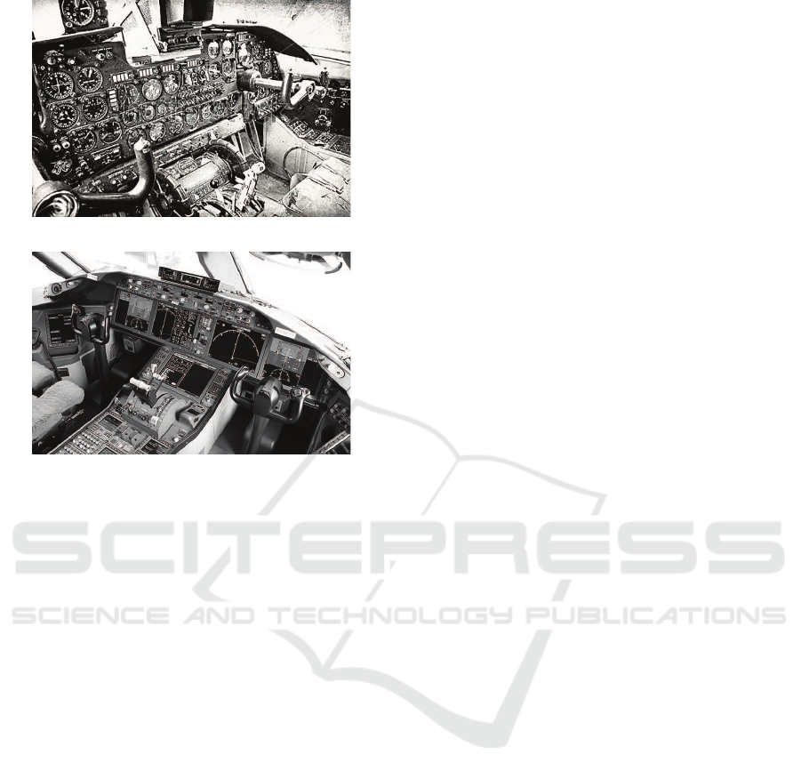
(a) classic
(b) modern
Figure 1: Evolution of the aviation flight deck.
This led cockpit design engineers to conclude that,
apparently, despite all their efforts in creating cock-
pits that contained all information necessary to fly, the
task is in fact too difficult for humans and could per-
haps be done better by a computer.
Hence, in the modern cockpit most of the basic
flying tasks (closing the nested loops of control, guid-
ance, and navigation) have been automated, and most
of the work to be done and the corresponding cogni-
tion needed to perform the job was moved to clever
computer algorithms. As a result, most of the time
the workload is low, to (steeply) increase only in sit-
uations that are unanticipated by the automation de-
signers, causing the automation to malfunction or not
function at all. And here it is where the other side of
the automation coin appears. Driven away from the
basic control loops, the pilots sometimes have low sit-
uation awareness, must make split-second decisions
in situations that automation cannot handle, poten-
tially contributing to human error.
In the evolution from the classic cockpit to the
modern flight deck, several useful and important in-
terface design principles have been developed. Exam-
ples are studies that stress the importance of proper il-
lumination, readability,and the use of colors and sym-
bols, and later studies that have led to the ‘laws’ of in-
tegrated, configural or object displays, emergent fea-
tures and the “principle of the moving part” (Johnson
and Roscoe, 1972; Roscoe et al., 1981). These design
principles are valid and improve access to data, the
transfer of information from sensors to humans. They
provide little help, however, for the designer to deter-
mine the “right” representation of the world, one that
facilitates human-automation teamwork, and support
the human pilot’s creative abilities.
Classic cockpits are examples of a design philos-
ophy called a “single sensor, single indicator” (SSSI)
(Vicente and Rasmussen, 1990), where one presents
all information available in a readable format, com-
municating with the humans on the level of signals
(Rasmussen, 1983). Since it is very difficult for pilots
to integrate all this information, automation was intro-
duced to help them improvetheir performance and re-
duce their workload, moving much of the thinking to
be done into computer algorithms. Within their lim-
ited scope of the problem domain, these algorithms
perform automatically, sometimes warning the pilots
for potential ‘problems’, i.e., communicating with
them on the level of signs, intended to elicit predeter-
mined (trained) solutions to situations that were antic-
ipated in the design of the automation. But what about
situations that were not anticipated beforehand, that
extend beyond the limited scope of the algorithms?
How to deal with the inevitable unanticipated vari-
ability in this complex domain?
We believe that, in the absence of some omni-
scient artificially intelligent entity that can cope with
this variability, we should strive for supporting pro-
ductive thinking of pilots, enabling them to creatively
invent solutions to these emergent, unexpected, multi-
dimensional problems. This requires that pilots learn
and maintain representations of the deep structure of
the work domain, through proper training and work-
ing with interfaces that communicate situations.
3 ECOLOGICAL APPROACH
In our work, we strive for a human-machine system
– defined here as automation and interfaces – that
shares the cognitive work between the automation
and humans. It is clear that much of the work to
be done can be performed much better (more accu-
rate, much faster, with many dimensions to simulta-
neously optimize) by computer algorithms. But since
these algorithms are invariably – and perhaps even
inevitably – limited in their scope and understand-
ing of the world in which they operate, at some point
the crew needs to be involved to decide in situations
where automation cannot decide, or interfere in sit-
uations where automation fails. We aim for a work
environment where the crew is involved, with reason-
able workload, high SA, working on representations

of the world that can be shared between automated
and human agents (Woods and Hollnagel, 2006; Van
Paassen et al., 2013; Klomp et al., 2016).
One of the main starting points of our work is
the classification that a flight deck as an open sys-
tem (Vicente, 1999). It has many “interfaces” with its
environment, e.g., weather, other traffic, terrain, air
traffic control (ATC). It has an extensive and some-
times rather complicated interaction with the environ-
ment, which makes its operation to be unpredictable,
and one cannot imagine and anticipate for all possi-
ble events in advance. In the absence of an infinitely
clever computer agent, as we see in science fiction
movies (e.g., HAL9000 in “2001 A Space Odyssey”),
we continue to depend on the adaptability of humans
to deal with the unanticipated variability.
To support humans in their cognitive work, it is
important to consider one of the main strengths of
the human mind. One of the distinctive features of
human intelligence is our amazing capacity to learn,
detect and use patterns and relations between our ac-
tions and what we perceive. Hence, we attempt to de-
sign graphical representations that provide ‘natural’
patterns that are linked to functionally-relevant rela-
tions among the state variables, such that humans be-
come ‘aware’ of situations with minimal cognitive ef-
fort. Our interface designs literally “show” the prob-
lem space to the pilot, and allow her to “work” on it,
in such a way that she can use the display represen-
tation as a template. This “problem space,” however,
is often not normally visible to the human eye, as in
our everyday activities such as eating a meal, walk
through a shopping center, and ride a bicycle.
In his “ecological” approach to visual perception,
Gibson emphasizes the “direct perception” capabili-
ties of humans, and the direct couplings that exist be-
tween perception and action (Gibson, 1966; Gibson,
1986). He introduced the concept of “affordance”,
possibilities and constraints for actions and achieving
goals, specified by the natural environment. Take for
example a pile of wood found on a beach. Depend-
ing on the situation at hand, a hungry person could
use the logs to cook; when cold, one could make a
fire to warm-up; Robinson Crusoe would perhaps try
to make a raft; when it starts raining one could try to
create an opportunity for shelter. This is just a sub-set
of possible meanings that the pile of wood may have
for an actor in the environment, all specified by the
natural display that can be directly perceived.
Vicente and Rasmussen took this stance when
proposing their “ecological approach” to design inter-
faces for complex systems (Vicente and Rasmussen,
1990; Vicente and Rasmussen, 1992). In Ecological
Interface Design (EID) one aims to transfer the cog-
nitive process of understanding and interacting with
complex systems to a perceptual process, where op-
erators interact with representations of that complex
process on (usually graphical) interfaces. An impor-
tant difference with interacting in the natural world
is that complex systems do often not allow humans
to “step-in and explore”. Rather, the interface is the
medium for interaction, and an ecological interface
should try to reveal the deep structure of the work do-
main in a way that is compatible with human percep-
tion, to make visible the invisible.
In his book “Cognitive Work Analysis,” Vicente
proposes six steps in the development of an ecological
display: Work Domain Analysis, Control Task Analy-
sis, Strategies Analysis, an Analysis of Social Organi-
zation and Cooperation, Worker Competencies Anal-
ysis, and finally the interface design (Vicente, 1999).
The Work Domain Analysis (WDA) is the most im-
portant one, as here the interface designer must an-
alyze the basic functioning of the work domain for
which the system has to fulfil its purpose. Rather than
trying to understand the cognitive processes that may
guide the operator (or computer algorithm) in doing
the work, the WDA focuses on the environment and
the ways in which the world constraints and physical
laws afford actions. Developing an appropriate rep-
resentation of this “action space,” independent of the
human or automated agent – a representation that is
true and valid for both – stands at the center of the
ecological approach.
In the past decades we developed several ecolo-
gical interfaces for the flight deck. Examples are a
Total Energy management display for basic aircraft
symmetrical flight control, that enables pilots to un-
derstand and act on exchanging their aircraft poten-
tial and kinetic energy (Amelink et al., 2005), Sepa-
ration Assistance displays that allow pilots to better
understand and act on other traffic (Van Dam et al.,
2008; Ellerbroek et al., 2011; Ellerbroek et al., 2013b;
Ellerbroek et al., 2013a), an ecological Synthetic Vi-
sion display (Borst et al., 2006; Borst et al., 2008;
Borst et al., 2010), and a display to work on four-
dimensional aircraft trajectories (Mulder et al., 2010;
Van Marwijk et al., 2011) We also explored various
EID designs for air traffic controllers in current and
future air traffic management environments (Tielrooij
et al., 2010; Klomp et al., 2011; Van der Eijk et al.,
2012; De Leege et al., 2013; Van Paassen et al., 2013;
Klomp et al., 2016), and controllers of multiple un-
manned aerial vehicles (Fuchs et al., 2014).
A common misconception on EID (Borst et al.,
2015) is that the ecological interface is simple, and
easy-to-use, one that quickly turns novices into ex-
perts. On the contrary, ecological interfaces are de-

signed for complex work and the complexity of the
work domain is reflected by the complexity in the
visual interface (Flach, 2012). Ecological interfaces
are made by experts to be used by experts, and it re-
quires the analyst to understand the problem space of
the work domain extremely well. This makes EID a
rather difficult and sometimes tedious approach to in-
terface design, one that easily fails. Generally speak-
ing, perhaps the approach better fits engineers than
human factors specialists, as it requires the analyst
to focus on the governing (often physical, dynamic)
principles of “the world” – the environment in which
the brain operates – rather than the brain itself. It re-
quires one to study what’s happening outside of the
human head, not inside.
4 EXAMPLE: AIRBORNE
SELF-SEPARATION
In the example we discuss the development of an eco-
logical interface that supports pilots in the task of
maintaining a safe separation with other traffic flying
in the vicinity of their own aircraft. Currently this is a
task done by air traffic control, but in the future parts
of the airspace may become unmanaged, and here the
pilots and their automation systems will become re-
sponsible for the separation task (SESAR, 2007).
An airborne separation assistance system (ASAS)
involves “the equipment, protocols, airborne surveil-
lance and <...> which enable the pilot to exercise re-
sponsibility, <...> for separation of his aircraft from
one or more aircraft” (ICAO SICASP/6-WP/44). The
ASAS functionalities, i.e., the work to be done by
automation and/or pilot, include: i) maintaining an
overview of the surrounding traffic; ii) detecting po-
tential loss of separation conflicts; iii) resolving con-
flicts and iv) preventing aircraft from running into
new conflicts. Note that a ‘conflict’ is defined here
as a potential loss of separation, in the future.
The development of ASAS systems has received a
lot of attention in the past decades and various proto-
types have been built and tested (for an overview see
(Hoekstra, 2001)). Common to many ASAS designs
is that they rely on trajectory prediction algorithms
which compute the “closest point of approach” (CPA)
and then have another computer algorithm “reason
about” the best way to deal with situations where the
CPA is predicted to become too small. Typically these
algorithms are programmed into a computer, and then
the interface designer is brought into play to create the
interface. In the light of the discussion in Section 2:
cognition is being put into the computer, hidden from
the pilot, and communication is done at the level of
signals (where is the other aircraft?) and signs (are
we moving too close? warn the pilot!).
Not surprisingly, in many ASAS evaluations the
typical ‘ironies’ of automation (Bainbridge, 1983;
Parasuraman and Riley, 1997) appeared: hidden ra-
tionale, confusion of the automation intent, disagree-
ment, lack of trust or complacency, low situation
awareness. “Why does the automation propose this
solution?”, “What will happen when I follow the au-
tomation’s advice?”, and “What if I don’t?”.
Apart from these issues, it is a fact that there will
always be cases which the automation designers and
engineers did not think of, because of the open and
complex nature of interaction of the aircraft in its en-
vironment. In addition, cockpit automation is typ-
ically only aware of a part of the situation (e.g., it
considers traffic) and ignorant of other constraints to
flight (e.g., terrain). Current automation does not fully
support pilots in these multi-constraint situations.
Before we start with the WDA, one should keep
in mind that self-separation problems typically evolve
very slowly. ASAS systems work with time horizons
of 3 to 5 minutes, with aircraft flying several hundreds
of miles apart, requiring pilots to zoom out their nav-
igation display to see the other aircraft, moving very
slowly on the display. This makes it very difficult for
them to detect possible conflict situations, and man-
age their resolution. Clearly, there is a need here to
make the separation task more “compatible” to hu-
man perception, and make visible the invisible.
4.1 Work Domain Analysis
In our work on the ASAS problem, which took us
several years, we were interested in finding a differ-
ent representation of the traffic separation problem,
other than the CPA-based solutions developed before.
Would there be a way to communicate with the pilot
at the “symbol” level, such that she would understand
the separation situation at a glance, directly act on it,
with or without the help of automation?
In an effort to construct a proper Abstraction Hier-
archy (AH), we started with numerous computer sim-
ulations of approaching aircraft, trying to figure out
what are the physical laws and abstract functions that
govern the dynamics of the separation control prob-
lem. We applied Rasmussen’s AH (Rasmussen et al.,
1994), at the five common levels of abstraction: Func-
tional purpose, Abstract function, Generalized func-
tion, Physical function and Physical form. Fig. 2 il-
lustrates one of the AH’s resulting from the analysis.
At each particular level, one considers the work do-
main at that level of abstraction, answering the ques-
tion “WHAT” happens on this level? Going one level
Functional Purpose
Abstract Function
Generalized Function
Physical Function
Physical Form
WHY ??
WHAT ??
HOW ??
Production
Efficiency
Safety
Absolute & relative
locomotion
Separation
Maneuvering
coordination
Obstruction
Control units
Traffic
Location & state
of own aircraft
Other aircraft
location & states
Figure 2: Abstraction Hierarchy for the separation assis-
tance work domain.
up then answers the question of “WHY” we have this
function, and moving one level down then answers
“HOW” the function is being performed.
An analysis of computer simulations of aircraft
flying in a two-dimensional airspace led us to the in-
sight that two “travel functions” form the core of the
separation problem. These act at the Abstract func-
tion level of the AH: ‘absolute and relative locomo-
tion’, and ‘separation’ (Van Dam et al., 2008). Manip-
ulating the relative motion of aircraft requires aircraft
to maneuver, and these maneuvers should be coordi-
nated such that separation is maintained; these are the
Generalized functions.
At the highest level, Functional purpose, the goal
of having an ASAS system is defined: ensure safety
at all times. This was obvious from the start, but our
simulations led us to add two more: be productive and
efficient. For particular geometries we discoveredthat
some maneuvers were indeed safe, but would lead to
situations where aircraft needed to make a more than
90 degree turn, or even fly back, or that it would take
very long for the conflict to be resolved.
Fig. 2 shows that at the Physical function level we
see the actual traffic that flies within the vicinity of
the own aircraft, and the control units that pilots have
to manipulate the generalized functions: their cockpit
interfaces to autopilot, throttle and flight management
systems. At the Physical form level we see the state
of the own aircraft and the locations and states of the
other aircraft involved.
This AH has had numerous iterations, as can be
seen in our publications over the years (Van Dam
et al., 2008; Ellerbroek et al., 2011; Ellerbroek et al.,
2013b). Indeed, we have been struggling with it
for quite some time as, other than in process control
where the abstract and generalized functions can be
quickly connected to the physics of the plant being
controlled (Vicente, 1999), in this separation prob-
lem the “physics” were not clear from the beginning.
Of course, the physics of aircraft flight dynamics are
known, but these are not very helpful in this particular
problem; they well describe the motions of one air-
craft, but not the physics of separating two (or more)
aircraft. Hence, we developed our own “meaningful
physics” (Van Paassen et al., 2005) for this problem
through the computer simulations stated above, yield-
ing the “travel functions.”
4.2 Traditional and Ecological
Approach
Reflecting on the “typical engineering approach” in
the context of the AH that results from the WDA, we
see that the computer algorithms are programmed to
“understand” and “work on” especially the Abstract
function and Generalized function levels. Through
the cockpit interfaces, the pilots are shown the el-
ements of the physical environment (other aircraft),
the Physical form level, they have their control but-
tons and dials to provide new set-points to their au-
tomated agents, the Physical function level, and they
are trained to understand the signals and signs that
the ASAS system provides them at the Functional
Purpose level. In this design, pilots will understand
why the system is there (functional purpose), they
are trained how to work with the system (physical
function, physical form), but they get little insight
into how the system actually works and deals with
the environmental constraints (abstract and general-
ized function levels).
In other words, the rationale behind the signals
and signs is “hidden” in the automation, and the pi-
lot has little insight into understanding how the com-
puter has interpreted and dealt with the traffic situa-
tion at the Abstract and Generalized function levels.
And indeed this is typical for many of the human-
machine systems and automated tools that have been
developed for the flight deck, hiding the rationale
from the pilots, putting the real cognition and pro-
cessing of data and situations into actions and advice
in pieces of automation that are non-transparent, lead-
ing to low situation awareness, workload peaks, and
all the ironies of automation.
Clearly then, in an ecological interface design ap-
proach the rationale of the automated algorithms and
the invisible but crucial elements of the world domain
should be visualized. In our designs we therefore aim
at “making visible the invisible”, showing pilots the
“world behind the glass” (Mulder, 2014) at the ab-
stract and generalized function levels, such that with
or without automated help they can reason about the
traffic situation themselves. Without automation they
should be able to detect and resolve conflicts them-
selves and also to do it in a way that is safe, effi-
Figure 3: Predictive ASAS, an earlier design for airborne assistance. On the Primary Flight Display (left): speed bands and
vertical speed bands; on the Navigation Display (right): heading bands. Figure obtained from (Ellerbroek, 2013).
cient and productive. With automation in place pilots
should be able to (much) better understand the sig-
nals and signs (warnings and resolution advisories)
that the automation provides, as the communication
will also show the deep structure that provides a con-
text for interpreting the meaning of these signals and
signs as situations (Flach et al., 2004).
4.3 Traditional Design
In the past 25 years much research has been con-
ducted on the self-separation problem, for instance in
the context of the “Free Flight” programs that ran in
the late 1990s. Numerous attempts were done to sup-
port pilots in understanding the essence of traffic con-
flicts and how the automation deals with them. Early
visualizations showed the point of closest approach
(CPA) on the navigation display, often graphically put
onto the display as ellipsoidal “no-go” zones.
Evaluations with these no-go zones showed that
new conflicts were triggered by maneuvers initiated
to resolve other conflicts. Engineers then came up
with predictive ASAS, based on computing “heading
bands” and “speed bands”, which show all possible
headingsof the own aircraft that would result in a con-
flict (assuming constant current speed) and all possi-
ble speeds that would result in a conflict (assuming
constant current heading), respectively. Fig. 3 illus-
trates how the traditional Primary Flight Display (left)
and Navigation Display (right) were extended with
the speed bands and heading bands overlays. Here,
the own aircraft is safe from conflicts, but the pilot
must not initiate any heading changes to the left that
are smaller than 35 degrees (heading band), or fly 15
knots slower (speed band).
Later a computer-aided “optimal” solution was
also shown, usually a combination of speed and head-
ing change, that was the best and most efficient way
out of the conflict (Hoekstra, 2001). With the speed
and heading bands, and the optimal solution pre-
sented, pilots indeed can see how to avoid other air-
craft. They have a hard time, however, finding out
themselves what would be the most efficient way to
resolve the conflict and especially to see and check
whether the computer-aided solution and heading and
speed bands are in fact correct. And the optimal so-
lution often appears right into the heading and speed
bands that act as “no go” states, as it consists of a
combination of heading and speed changes that are
smaller than resolving the conflict with either head-
ing or speed. This causes confusion and a lack of
confidence, an automation irony at work. In addition,
when the own aircraft is involved in a multi-aircraft
conflict, more and more no-go bands are presented
and it becomes difficult for pilots to relate these to
the individual aircraft involved. This iteration of typ-
ical engineering and interface design did not end up
with an easy-to-use interface. The representation of
the problem taken – CPA, heading and speed bands –
has in fact obscured the way the world works.
4.4 Ecological Design
We took a different approach to the problem, based
on visualizing the full affordances of relative and ab-
solute motion. For a comprehensive description of
the design and the process we have gone through, the
reader is referred to (Van Dam et al., 2008).
When the locations and velocities of all aircraft
flying near the own aircraft are known, then we can
compute the set of relative velocity vectors that will
bring the own aircraft into a conflict situation with
(a) ecological overlay
current heading
tip of vector
max. velocity
min. velocity
aircraft position
aircraft velocity
vector
Forbidden Beam Zone
90 deg. left
90 deg. right
(b) display elements
Figure 4: Simplified version of the Ecological separation
assistance display: the “state-vector” envelope for 2D mo-
tion (top); elements of the display (bottom).
each other aircraft. The pilot must change the veloc-
ity vector of her own aircraft – its direction (=heading
of the own aircraft) and/or magnitude (=speed of the
own aircraft) – in such a way that its tip does not be-
long to this set. In this way we developed an own
aircraft-centered presentation of this relative motion,
which shows the affordances of “hit” and “avoid” that
can be directly perceived and acted upon by the pilot
(or automation). We later found out that in robotics
similar solutions were developed (Tychonievichet al.,
1989; Chakravarthy and Ghose, 1998; Fiorini and
Shiller, 1998); we also found the Battenberg course
indicator (dating back to 1892) which visualizes ship
maneuvering constraints in a similar way. We ex-
tended and unified all existing solutions to their full
2D + time potential in (Mercado-Velascoet al., 2015).
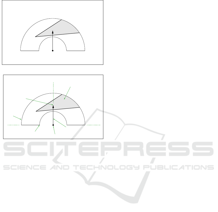
Fig. 4(a) shows the ecological ASAS display, in
its most elementary form: a two-dimensional semi-
circular presentation used as an overlay on the current
Navigation Display, Fig. 3. Later we also developed
vertical (Heylen et al., 2008), co-planar (Ellerbroek
et al., 2013b; Ellerbroek et al., 2013a) and 3-D or-
thogonal (Ellerbroek et al., 2011) presentations.
Fig. 4(b) shows the display elements. The own
aircraft ‘velocity vector’ is the first key element. The
size of the vector can be changed, indicating speed
changes: it can be made larger (fly faster) or smaller
(fly slower), but the length cannot exceed the veloc-
ity limits indicated by the two semi-circles. The tip
of the velocity vector cannot move out of these lim-
its, which represent constraints “internal” to the own
aircraft; they depend on performance limits (physical
function). The direction of the vector can also change,
i.e., rotated to the left and right, indicating heading
changes. Heading changes larger than 90 degrees left
or right are possible but are considered to be not very
productive (functional purpose).
The second key element of the display is the
triangular-shaped zone that visualizes the set of own
aircraft velocity vectors that will result in a conflict
with another near-by aircraft. All heading and speed
settings of the own aircraft that result in the tip of the
velocity vector to be located within this “forbidden
beam zone” will be unsafe (functional purpose). Vice
versa, all heading and speed settings of the own air-
craft that result in a velocity vector tip outside this
zone are safe. These constraints to our own aircraft
motion are caused by the other aircraft, the “external”
constraints to flight (abstract function).
With our display, pilots can directly perceive
whether they are in conflict, and also that many op-
tions exist to get out of trouble by changing their air-
craft speed, or heading, or both (generalized func-
tion). In the situation illustrated in Fig. 4, pointing
the own aircraft velocity vector below the zone (i.e.,
slow down) means that the other aircraft will even-
tually pass us in front; pointing the vector above the
zone (speed up) means that we will pass the other air-
craft in front. We could also choose to maintain cur-
rent speed, and turn the vector clockwise with, say, 40
degrees, which will also resolve the conflict and have
the other aircraft pass us in front. Hence, the display
shows the future consequences of our possible actions
in a directly perceivable way. It explicitly visualizes
the dynamics of relative motion (abstract function)
and the ways to fulfill our functional purposes through
manipulating this relative motion (generalized func-
tion). Our display properly visualizes and connects
the means of flying (change heading, speed) with the
ends of flight (being safe, productive and efficient), a
true ecological interface (Van Dam et al., 2008).
Working with this representation led to some im-
portant insights. First of all, our display shows the
complete “solution space” to pilots, and includes all
possible heading bands (see Fig. 5(a)) and speed
bands (see Fig. 5(b)) of the traditional design. That is,
when reducing speed to, say, 200 kts, and then chang-
ing the aircraft heading, the part of the 200 kts-circle
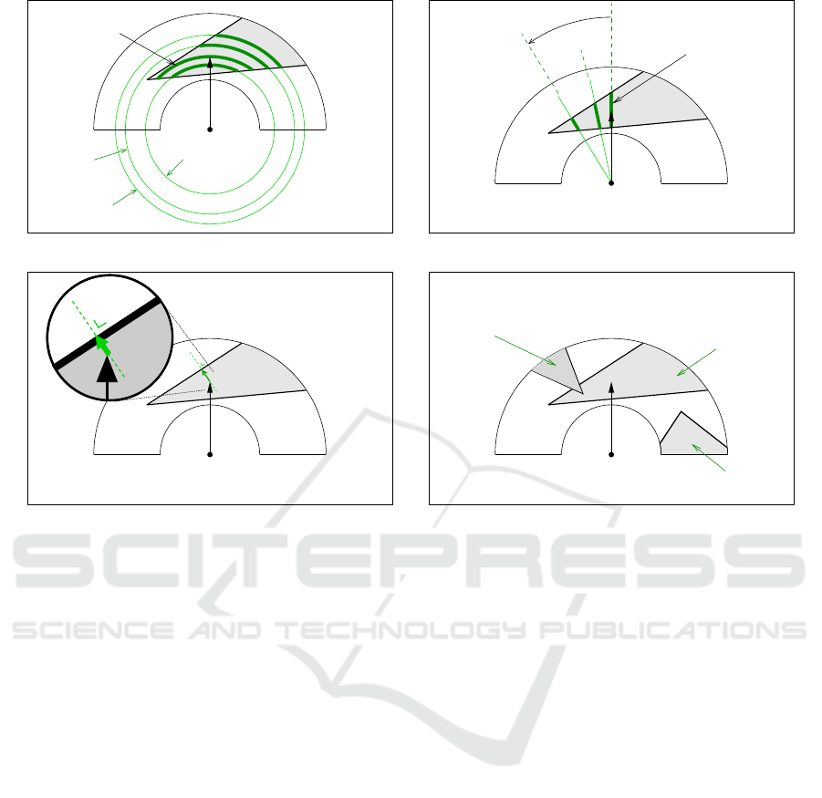
200 kts
250 kts
270 kts
heading band of
current speed
(a) the display contains all “heading band” constraints
15 deg.
40 deg.
speed band of
current heading
(b) the display contains all “speed band” constraints
(c) the display specifies the “optimal solution”: the small-
est state change
intruder #1
intruder #2
intruder #3
(d) the display specifies the constraints of multiple aircraft
conflicts
Figure 5: Example of how the ecological separation display specifies all the constraints.
that coincides with the forbidden beam zone, equals
the heading band computed by the predictive-ASAS
algorithm. The forbidden beam zone represents all
possible heading bands for this particular conflict, see
Fig. 5(a). Similarly, for each possible heading change,
like 40 degrees left of the current heading, the part of
the 40 degree line that coincides with the forbidden
zone, shows the velocities which lead to a conflict,
the speed bands, see Fig. 5(b).
With this visual, symbolic presentation of the self-
separation situation the pilot can also directly see the
optimal solution: the smallest state change of the own
velocity vector that will move the tip of the vector out-
side of the zone, see Fig. 5(c). Here, as shown by the
zoomed-in inset of the figure, a small heading change
to the left, combined with a small speed increase, will
bring the tip of the own aircraft velocity vector out-
side of the zone, avoiding the conflict; the pilot can
also directly see that she will then pass the other air-
craft in front.
One of the most interesting characteristics of our
display is that, when more aircraft are flying near-
by, these may all cause external constraints that limit
the own aircraft motion possibilities, limiting the so-
lution space; see Fig. 5(d) for a situation with three
other ‘intruder’ aircraft. In this rather complex situ-
ation, which may happen in very dense parts of the
airspace, the pilot can directly see that a way to re-
solve the conflict with intruder #1, one that does not
lead to conflicts with the other two intruders, would
be to speed up, and move the tip of the velocity vector
above the forbidden beam zone caused by the first in-
truder. He will then pass that aircraft in front, and also
pass the other two aircraft in front. Hence, the dis-
play is also suitable for resolving multi-aircraft sepa-
ration problems, although in these cases determining
the best, optimal maneuver may be less obvious and
could perhaps be found by an automated agent.
Fig. 6 shows the Navigation Display augmented
with the ecological overlay at the bottom center. Here
we have a conflict with two aircraft (callsigns AA386
and AA387), and one way to solve both conflicts
would be to speed up, such that the own aircraft
passes both other aircraft in front. Another solution
(of many solutions!) would be to speed up a little and
turn 30 degrees to the right, such that we pass AA386
in front, and we pass AA387 behind.
4.5 Lessons Learned
When considering the differences between traditional
designs and ecological designs, the latter are richer
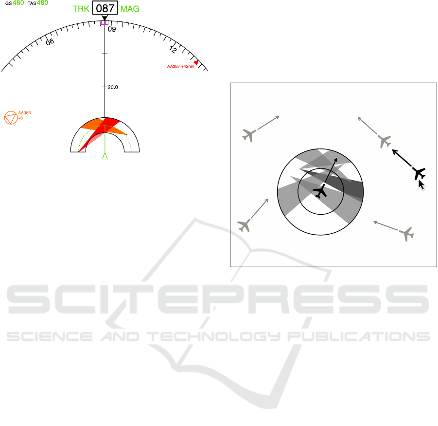
Figure 6: Ecological airborne assistance overlay added to
the Navigation Display.
and provide more meaningful information about the
conflict situation. It allows pilots to quickly obtain a
good understanding of the situation, and the visual-
ization of relative motion allows the pilots to directly
observe the possibilities for actions and the conse-
quences of taking an action. We think this is what
traffic ‘situation awareness’ is all about.
At the core of the design is the work domain anal-
ysis, which helps the analysts and designers to be-
come experts in the problem at hand, understand-
ing the functional means-ends relationships of the
system-to-be-built, independent of who or what will
do the actual work. It shows what aspects of the work
domain are so crucial that they have to be visualized
on the display, and will help to explore what possible
representations of the world exist and could be used
for the system design. The iterations that follow, in-
volving prototyping and testing may lead to novel in-
sights into the problem and may result in adaptations
of the analysis, the representation, and the interface.
Note that the ecological interface design does not
prohibit the use of automated help. We do not plead
against automation. On the contrary, the ecologi-
cal interface could well be the “transparent window
to the automation” that is mandatory when pilots are
responsible to verify the automated agents’ advice.
The internal and external constraints as visualized on
the ecological interface are constraints of “the world”
which also hold for automation: the WDA and corre-
sponding ecological interface are actor-independent.
In this respect, we have successfully applied the
same concepts to air traffic control. Here, an analy-
sis showed that close to 50% of all short-term conflict
alerts were caused by operator’s responses to previ-
ous alerts (Lillo et al., 2009). That is, with the cur-
rent radar-like interface, when air traffic controllers
‘solve’ a conflict (which are commonly detected by
computer algorithms, warning the controller) their
solution triggers new conflicts later. Fig. 7 shows
our ecological overlay positioned on an experimen-
tal ATC interface. When the automation has warned
the controller, she can click on one of the aircraft in-
volved, and directly see solutions that solve the con-
flict and do not lead to new conflicts in the near future.
Figure 7: Evolution of the ecological airborne assistance
display to an ecological plan view ATC interface; the Solu-
tion Space Diagram.
It is a nice example of automation and humans
working as a team, and this set-up allows also to move
back and forth between several levels of automation
authority. That is, one could opt for not only warning
the controller, but also presenting a resolution advice
to her. When equipped with the solution space over-
lay, the controller can then check very easily whether
the automation advice is correct, and how the traffic
situation will emerge in the near future. We are con-
fident that, with the help of our ecological overlays,
the 50% of conflict alerts triggered by the controller’s
earlier responses can be brought down to a minimum,
yielding a safer and more efficient air transport.
5 CLOSING STATEMENTS
At the start of this paper, we have asked ourselves the
question whether there exists an approach to automa-
tion and interface design that helps pilots in perform-
ing their cognitive work, and leads to higher level of
situation awareness. In our view, it is the ecologi-
cal approach to human-machine systems design that
allows the analysts to capture the essence of what is
needed, to construct interfaces and automation that al-
low human and automated agents to work together.

Note that a good ecological interface reflects the
complexity of the work domain. This means that in
order to construct one, the analyst should become an
expert herself. In addition, when the work domain
analysis is done, their is no recipe for creating the ac-
tual display itself. In our experience, several iterations
are needed, often in combination with human-in-the-
loop evaluations of prototypes. Deciding on what sys-
tem ‘state variables’ are used to design the interface
and automated tools is crucial. Aviation has several
examples where, because of (on hindsight) unfortu-
nate design decisions early on in the development of
systems – like in autopilots, see (Lambregts, 2013) –
interfaces and automation are not complete. The re-
sulting (human factors) problems will continue to pop
up now and then, but the real problem is rooted deeper
inside these legacy systems.
In properly representing situations to pilots, it is
not our intention to put the automation aside. On the
contrary, our ecological interfaces are there to facil-
itate coordination between humans and automation,
creating the transparency that is needed for pilots to
understand situations and judge the logic underlying
the automation’s actions or advices. A joint cogni-
tive human-machine system should be strived for in
cockpits, in which cognition can be dynamically dis-
tributed, moving back and forth between human and
automated agents. The ecological interface provides
pilots the “window on the world”, based on a repre-
sentation that can be used by humans and automation
to understand and act upon emerging situations.
REFERENCES
Amelink, M. H. J., Mulder, M., Van Paassen, M. M.,
and Flach, J. M. (2005). Theoretical Foundations
for a Total Energy-Based Perspective Flight-Path Dis-
play. The International Journal of Aviation Psychol-
ogy, 15(3):205–231.
Bainbridge, L. (1983). Ironies of Automation. Automatica,
19(6):775–779.
Billings, C. E. (1997). Aviation Automation – The Search
for a Human-Centered Approach. Lawrence Erlbaum
Associates, Inc., Mahwah (NJ).
Borst, C., Flach, J. M., and Ellerbroek, J. (2015). Beyond
Ecological Interface Design: Lessons from Concerns
and Misconceptions. IEEE Transactions on Human-
Machine Systems, 45(2):164–175.
Borst, C., Mulder, M., and Van Paassen, M. M. (2010). De-
sign and Simulator Evaluation of an Ecological Syn-
thetic Vision Display. Journal of Guidance, Control
& Dynamics, 33(5):1577–1591.
Borst, C., Sjer, F. A., Mulder, M., Van Paassen, M. M., and
Mulder, J. A. (2008). Ecological Approach to Support
Pilot Terrain Awareness After Total Engine Failure.
Journal of Aircraft, 45(1):159–171.
Borst, C., Suijkerbuijk, H. C. H., Mulder, M., and Van
Paassen, M. M. (2006). Ecological Interface Design
for Terrain Awareness. The International Journal of
Aviation Psychology, 16(4):375–400.
Breton, R. and Rousseau, R. (2001). Situation Awareness:
A Review of the Concept and its Measurement. Tech-
nical report DRDC TR-2001-220, Defence research
and development Canada – Valcartier.
Chakravarthy, A. and Ghose, D. (1998). Obstacle Avoid-
ance in a Dynamic Environment: A Collision Cone
Approach. IEEE System, Man and Cybernetics - Part
A: Systems and Humans, 28(5):562–574.
De Leege, A. M. P., Van Paassen, M. M., and Mulder, M.
(2013). The Time-Space Diagram as an Assistance for
ATC in Monitoring Closed Path Continuous Descent
Operations. Journal of Aircraft, 50(5):1394–1408.
Ellerbroek, J. (2013). Airborne Conflict Resolution In Three
Dimensions. Ph.D. dissertation, Faculty of Aerospace
Engineering, Delft University of Technology.
Ellerbroek, J., Brantegem, K. C. R., Van Paassen, M. M.,
de Gelder, N., and Mulder, M. (2013a). Experimen-
tal Evaluation of a Coplanar Airborne Separation Dis-
play. IEEE Transactions on Human-Machine Systems,
43(3):290–301.
Ellerbroek, J., Brantegem, K. C. R., Van Paassen, M. M.,
and Mulder, M. (2013b). Design of a Coplanar Air-
borne Separation Display. IEEE Transactions on
Human-Machine Systems, 43(3):277–289.
Ellerbroek, J., Visser, M. van Dam, S. B. J., Mulder, M.,
and Van Paassen, M. M. (2011). Design of an Air-
borne Three-Dimensional Separation Assistance Dis-
play. IEEE Transactions on Systems, Man & Cyber-
netics, Part A, 41(5):863–875.
Endsley, M. (1995a). Measurement of Situation Awareness
in Dynamic Systems. Human Factors, 37(1):65–84.
Endsley, M. (1995b). Toward a Theory of Situation Aware-
ness. Human Factors, 37(1):32–64.
Fiorini, P. and Shiller, Z. (1998). Motion Planning in Dy-
namic Environments Using Velocity Obstacles. Inter-
national Journal of Robotics Research, 17:760–772.
Flach, J. M. (2012). Complexity: Learning to Muddle
Through. Cognition, Technology & Work, 14(3):187–
197.
Flach, J. M., Mulder, M., and Van Paassen, M. M. (2004).
The Concept of the Situation in Psychology. In Ban-
bury, S. and Tremblay, S., editors, A Cognitive Ap-
proach to Situation Awareness: Theory and Applica-
tion, pages 42–60. Ashgate Publishing, Oxon (UK).
ISBN 0754641988.
Fuchs, C., Borst, C., De Croon, G. C. H. E., Van Paassen,
M. M., and Mulder, M. (2014). An Ecological Ap-
proach to the Supervisory Control of UAV Swarms.
Int. J. of Micro-Air Vehicles, 6(4):211–224.
Gibson, J. J. (1966). The Senses Considered as Perceptual
Systems. Houghton Mifflin, Boston (MA).
Gibson, J. J. (1986). The Ecological Approach to Visual
Perception. Lawrence Erlbaum Associates, Hillsdale
(NJ). originally published in 1979.

Heylen, F. M., Van Dam, S. B. J., Mulder, M., and Van
Paassen, M. M. (2008). Design of a Vertical Separa-
tion Assistance Display. Proc. of the AIAA Guidance,
Navigation and Control Conference, Honolulu (HI),
USA, August 18-21, (AIAA 2008-6969).
Hoekstra, J. M. (2001). Designing for Safety: the Free
Flight Air Traffic Management Concept. Ph.D. dis-
sertation, Faculty of Technology, Policy and Manage-
ment, Delft University of Technology.
Johnson, S. L. and Roscoe, S. N. (1972). What Moves, the
Airplane or the World? Human Factors: The Jour-
nal of the Human Factors and Ergonomics Society,
14(2):107–129.
Klomp, R. E., Borst, C., Van Paassen, M. M., and Mul-
der, M. (2016). Expertise Level, Control Strategies,
and Robustness in Future Air Traffic Control Decision
Aiding. IEEE Transactions on Human-Machine Sys-
tems, 46(2):255–266.
Klomp, R. E., Van Paassen, M. M., Mulder, M., and
Roerdink, M. I. (2011). Air Traffic Control Interface
for Creating 4D Inbound Trajectories. In Proc. of the
16th International Symposium on Aviation Psychol-
ogy (ISAP), Dayton (OH), May 2-5, pages 263–268.
Wright State University.
Lambregts, A. A. (2013). TECS Generalized Airplane Con-
trol System Design - An Update. In Chu, Q. P., edi-
tor, Advances in Aerospace Guidance, Navigation and
Control,, pages 503–534. Springer Verlag, Berlin.
Lillo, F., Pozzi, S., Tedeschi, A., Ferrara, G., Matrella, G.,
Lieutaud, F., Lucat, B., and Licu, A. (2009). Cou-
pling and Complexity of Interaction of STCA Net-
works. In Proc. of the EUROCONTROL Innovative
ATM Research Workshop, Br´etigny-sur-Orge, France,
Dec. 1-3, pages 1–12. EUROCONTROL.
Mercado-Velasco, G. A., Borst, C., Ellerbroek, J., Van
Paassen, M. M., and Mulder, M. (2015). The Use of
Intent Information in Conflict Detection and Resolu-
tion Models Based on Dynamic Velocity Obstacles.
IEEE Transactions on Intelligent Transportation Sys-
tems, 16(4):2297–2302.
Mulder, M. (2014). Ecological Flight Deck Design: the
World Behind the Glass. In Viduluch, M. A., Flach,
J. M., and Tsang, P. S., editors, Advances in Aviation
Psychology, pages 103–120. Ashgate. ISBN 978-1-
4724-3840-9.
Mulder, M., Winterberg, R., Van Paassen, M. M., and Mul-
der, M. (2010). Direct Manipulation Interfaces for
In-Flight Four-Dimensional Navigation. International
Journal of Aviation Psychology, 20(3):249–268.
Parasuraman, R. and Riley, V. A. (1997). Humans and Au-
tomation: Use, Misuse, Disuse, Abuse. Human Fac-
tors, 39:230–253.
Rasmussen, J. (1983). Skills, Rules, and Knowledge; Sig-
nals, Signs, and Symbols, and other Distinctions in
Human Performance Models. IEEE Transactions on
Systems, Man, and Cybernetics, 13:257–266.
Rasmussen, J., Pejtersen, A., and Goodstein, L. (1994).
Cognitive Systems Engineering. Wiley, New York.
Roscoe, S. N., Corl, L., and Jensen, R. S. (1981). Flight Dis-
play Dynamics Revisited. Human Factors, 23(3):341–
353.
SESAR (2007). Sesar Definition Phase D3: The ATM Tar-
get Concept. Technical report no. DLM-0612-001-02-
00, EUROCONTROL.
Tielrooij, M., In ‘t Veld, A. C., Van Paassen, M. M., and
Mulder, M. (2010). Development of a Time-Space
Diagram to Assist ATC in Monitoring Continuous De-
scent Approaches. In Mulder, M., editor, Air Traffic
Control, pages 135–147. SCIYO.
Tychonievich, L., Zaret, D., Mantegna, J., Evans, R.,
Muehle, E., and Martin, S. (1989). Maneuvering-
Board Approach to Path Planning with Moving Ob-
stacles. In International Joint conference on Artificial
Intelligence, pages 1017–1021.
Van Dam, S. B. J., Mulder, M., and Van Paassen, M. M.
(2008). Ecological Interface Design of a Tactical Air-
borne Separation Assistance Tool. IEEE Trans. on
Systems, Man & Cybernetics, Part A, 38(6):1221–
1233.
Van der Eijk, A., Borst, C., In ‘t Veld, A. C., Van Paassen,
M. M., and Mulder, M. (2012). Assisting Air Traffic
Controllers in Planning and Monitoring Continuous-
Descent Approaches. J. of Aircraft, 49(5):1376–1390.
Van Marwijk, B. J. A., Borst, C., Mulder, M., Mulder, M.,
and Van Paassen, M. M. (2011). Supporting 4D Tra-
jectory Revisions on the Flight Deck: Design of a
Human-Machine Interface. International Journal on
Aviation Psychology, 21(1):35–61.
Van Paassen, M. M., Borst, C., Klomp, R., Mulder, M., Van
Leeuwen, P., and Mooij, M. (2013). Designing for
Shared Cognition in Air Traffic Management. Journal
of Aerospace Operations, 2(1):39–51.
Van Paassen, M. M., Mulder, M., Van Dam, S. B. J., and
Amelink, M. H. J. (2005). “Meaningful Physics” Or
Finding a System Description Suitable for Ecological
Interface Design. Proc. of the 13th International Sym-
posium on Aviation Psychology, Oklahoma City (OK),
USA, April 18-21, pages 592–596.
Vicente, K. J. (1999). Cognitive Work Analysis – Toward
Safe, Productive and Healthy Computer-Based Work.
Lawrence Erlbaum Associates, Mahwah (NJ).
Vicente, K. J. and Rasmussen, J. (1990). The Ecology
of Human-Machine Systems II: Mediating “Direct-
Perception” in Complex Work Domains. Ecological
Psychology, 2(3):207–249.
Vicente, K. J. and Rasmussen, J. (1992). Ecological Inter-
face Design: Theoretical Foundations. IEEE Trans.
on Systems, Man, and Cybernetics, 22(4):589–606.
Wiener, E. L. and Curry, R. E. (1980). Flight-Deck
Automation: Promises and Problems. Ergonomics,
23(10):995–1011.
Woods, D. D. and Hollnagel, E. (2006). Joint Cognitive
Systems: Patterns in Cognitive Systems Engineering.
Taylor and Francis, Boca Ratan (FL).
